Mechanical design and CAD education teaches students to turn imagination into something that can survive inspection. A good idea is not yet a design; a design is an idea that has learned discipline—dimensions, constraints, interfaces, tolerances, and the quiet logic of “will it actually fit, move, carry load, and be made?” This diagram shows that discipline as a flow. The inputs bring the raw materials of design thinking—fundamentals and requirements—while the controls keep the work honest: curriculum topics define the sequence of skills, and evaluation criteria demand that choices be justified, not merely drawn. Inside the central function, students practice the real craft of engineering: translating intent into geometry, geometry into assemblies, assemblies into checks, and checks into revisions. The mechanisms—CAD software and supporting resources—provide the workshop of the mind, where iteration is fast, errors are visible, and improvements are traceable. The outputs are what the modern engineer must be able to produce: students who can design with clarity, and models that communicate reliably—ready for analysis, manufacturing, and collaboration rather than existing as beautiful but fragile sketches.
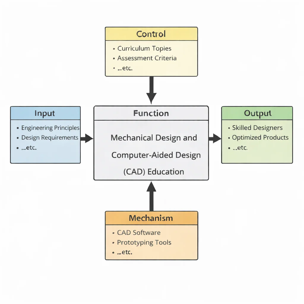
This IDEF0 (Input–Control–Output–Mechanism) diagram summarizes Mechanical Design and Computer-Aided Design (CAD) Education as a structured learning system. Inputs on the left represent what learners work from—design fundamentals, requirements, and practical constraints that shape mechanical solutions. Controls at the top (curriculum topics and evaluation criteria) define what must be learned and how competence is judged, ensuring that design work is systematic, testable, and aligned with professional expectations. The central function, Mechanical Design and Computer-Aided Design (CAD) Education, transforms these inputs and controls into applied skill through guided instruction and practice. Outputs on the right represent the educational results: design-ready students and validated models that can be communicated, reviewed, and refined. Mechanisms at the bottom represent the enabling resources—CAD software, design tools, and supporting lab/workshop facilities—that make modeling, iteration, and verification possible.
Mechanical design and computer-aided design (CAD) are central to modern engineering, enabling the creation, analysis, and optimization of mechanical systems with unprecedented precision. This discipline integrates theoretical principles with practical tools, allowing engineers to develop innovative solutions in sectors ranging from automotive engineering to biomechanical systems. The design process is enriched by a solid grounding in solid mechanics, which informs how materials deform and respond to loads, and vibrational analysis that ensures dynamic stability.
CAD tools streamline the development of complex geometries and assemblies while allowing integration with advanced simulation methods. These include thermal behavior modeling linked to thermodynamics and heat transfer, as well as performance assessments under pressure or flow conditions guided by fluid mechanics. Modern designers also draw on nanotechnology and advanced materials to enhance component strength, reduce weight, or improve thermal performance.
Beyond design aesthetics and functionality, engineers must account for how products will be manufactured and used. Insights into industrial and manufacturing technologies, including 3D printing and advanced manufacturing techniques, influence decisions from the start. CAD is deeply connected with digital twin technology, which allows real-time performance simulation of physical components before actual fabrication.
Mechanical design is inherently multidisciplinary. Efficient control and regulation of machine components depend on a strong foundation in control systems, while understanding production constraints is informed by manufacturing engineering and process optimization. Factors like ergonomics ensure the designs are user-friendly and safe, and principles from Industry 4.0 and sustainability encourage efficiency and eco-responsibility.
To produce quality parts at scale, engineers must also incorporate knowledge of quality control, lean manufacturing, and the broader supply chain. As design integrates further with automation, knowledge of robotics and automation systems becomes increasingly essential. Altogether, mechanical design and CAD form the creative and analytical bedrock for engineers seeking to bring precise, functional, and future-ready machines into reality.
- Mechanical Engineering topics:
- Mechanical Engineering – Overview
- Solid Mechanics
- Fluid Mechanics & Hydraulics
- Thermodynamics & Heat Transfer
- Vibrations & Acoustics
- Mechanical Design & CAD
- Manufacturing & Production Engineering
- Control Systems in ME
- Robotics & Automation in ME
- Nanotechnology & Advanced Materials in ME
- Biomechanical Engineering
- Automotive Engineering
Table of Contents
Core Concepts of Mechanical Design
Design Principles
Mechanical design is a foundational aspect of engineering that blends creativity with scientific precision to bring functional, durable, and efficient components to life. At its core, mechanical design is about creating systems that can withstand mechanical stresses, operate within prescribed limits, and fulfill the needs of users across a variety of environments and industries. Whether the goal is to build a suspension system for an off-road vehicle, develop a prosthetic limb, or improve the cooling system in an industrial plant, sound mechanical design principles must be applied to achieve the desired outcome.
- Functionality:
- Functionality ensures that each component and system operates as intended under various operating conditions. For example, gears must not only mesh correctly but must also transmit torque effectively while minimizing power loss and mechanical wear.
- Durability:
- A critical aspect of mechanical design is ensuring durability—components must endure cyclic loads, temperature fluctuations, and exposure to corrosive environments without failing prematurely. The selection of appropriate materials, treatments, and coatings plays a vital role in achieving long-term reliability.
- Cost-Effectiveness:
- Mechanical design must often balance ideal performance with budgetary constraints. Engineers optimize part geometries to reduce material usage, choose cost-efficient manufacturing processes, and design for ease of assembly and maintenance to reduce lifecycle costs.
- Aesthetics:
- In consumer-facing products, aesthetics are also important. A well-designed object must not only work effectively but also appeal to end users through clean lines, thoughtful ergonomics, and satisfying tactile feedback.
Design Process
The mechanical design process is an iterative sequence that translates an idea into a fully functional physical product. It is structured to ensure that every critical consideration—from client requirements to manufacturability—is addressed systematically. Each stage allows for evaluation and refinement to reduce risk and increase efficiency.
- Problem Identification:
- This involves identifying the design challenge, including technical requirements, functional goals, environmental constraints, and user needs. A clear design brief is essential to guide the process.
- Concept Development:
- Brainstorming sessions generate multiple ideas, with emphasis on creativity and lateral thinking. Sketches, block diagrams, and initial feasibility studies help prioritize promising directions.
- Preliminary Design:
- Once a concept is chosen, engineers begin laying out system architecture, selecting candidate materials, and defining component interactions. This stage may involve rough CAD models and early calculations.
- Detailed Design:
- Detailed specifications including dimensions, tolerances, and material properties are established. Engineering drawings are finalized for use in analysis and eventual manufacturing.
- Analysis and Simulation:
- Computational methods like finite element analysis (FEA) and computational fluid dynamics (CFD) are applied to simulate loads, stresses, vibrations, and heat flow. This step helps verify that the design will perform as expected.
- Prototyping:
- Prototypes allow for real-world testing of mechanical function, fit, and user interaction. Engineers may use rapid prototyping methods like 3D printing or CNC machining to create early versions of the product.
- Production:
- In this final stage, the design is released for full-scale manufacturing. Engineers collaborate with production teams to ensure all components are manufactured and assembled to specification.
Design Optimization
Optimization in mechanical design involves enhancing performance while minimizing cost, weight, or energy usage. Engineers utilize design of experiments (DOE), topology optimization, and simulation tools to iterate toward optimal configurations.
- Weight Reduction:
- Reducing mass without compromising strength is crucial in aerospace, automotive, and robotics. This may involve the use of advanced lightweight materials such as carbon fiber composites or titanium alloys, and the implementation of lattice structures generated by topology optimization algorithms.
- Energy Efficiency:
- Optimizing flow paths, reducing friction, and improving thermal management all contribute to more energy-efficient designs. For example, optimizing the aerodynamic profile of vehicle components can significantly reduce fuel consumption. According to insights from ScienceDirect’s mechanical design research, integrating energy recovery systems has also become a focus in sustainable design practices.
- Performance Enhancement:
- Engineers continually refine designs to improve characteristics like load capacity, response time, or vibration resistance. Techniques such as modal analysis and fatigue testing are used to ensure enhanced reliability and safety under various operating conditions.
Role of CAD in Mechanical Design
Computer-Aided Design (CAD) has become an indispensable tool in mechanical engineering, transforming how products are conceptualized, developed, analyzed, and brought to market. By enabling engineers to build and test digital prototypes, CAD significantly reduces design cycles, minimizes material waste, enhances product quality, and lowers production costs. Beyond modeling, CAD serves as a critical bridge between design intent and physical realization by integrating analysis tools, facilitating collaboration, and supporting rapid iteration across multidisciplinary teams.
3D Modeling
At the heart of CAD is 3D modeling, where engineers craft virtual representations of mechanical parts and assemblies. These models form the basis for analysis, simulation, and manufacturing. By shifting from 2D drawings to parametric, direct, and surface modeling techniques, designers gain control and flexibility in adapting their ideas.
- Parametric Modeling:
- This method enables the use of design parameters—such as length, diameter, and angle—that can be adjusted to instantly regenerate the model. It supports design automation and configuration management. For instance, changing the wall thickness of a pipe across hundreds of models can be done in seconds.
- Direct Modeling:
- Unlike parametric modeling, direct modeling allows engineers to manipulate geometry intuitively without dependency on feature history. This is useful for late-stage design changes or editing imported geometry from other CAD systems.
- Surface Modeling:
- Used extensively in industries like automotive and consumer electronics, surface modeling enables the creation of smooth, flowing surfaces necessary for aerodynamic and ergonomic designs. It is especially effective for organic shapes and styling.
- Assembly Modeling:
- Multiple components are assembled within a digital environment to verify part fit, analyze motion, and ensure design completeness. Engineers simulate part interaction to detect interferences and validate constraints such as rotational freedom or linear alignment.
Prototyping
CAD reduces the need for costly physical iterations by enabling virtual prototypes. These models not only visualize geometry but simulate the product’s functional aspects early in the development lifecycle.
- Virtual Prototypes:
- Engineers can validate designs against real-world forces, environmental conditions, and human interaction scenarios. For example, vehicle chassis can be tested under crash loadings, and ventilation systems can be evaluated for airflow efficiency—all before physical models are built.
- Additive Manufacturing Integration:
- CAD files can be directly exported as STL or AMF files for 3D printing. This integration facilitates rapid iteration, enabling designers to test form, fit, and function in days rather than weeks, thereby accelerating product development cycles.
Simulation and Analysis
Many CAD platforms come integrated with simulation capabilities that allow engineers to conduct thorough performance evaluations. This includes structural, thermal, and fluid analyses that replicate real-world conditions to ensure safe and optimal designs.
- Finite Element Analysis (FEA):
- FEA breaks down complex structures into smaller elements to assess stress distribution, deformation, and fatigue life under static and dynamic loading. It is particularly vital in designing bridges, load-bearing machines, and safety-critical systems.
- Computational Fluid Dynamics (CFD):
- CFD simulates the movement of fluids around objects and inside channels, such as airflow through a duct or cooling fluid in an engine. Engineers optimize heat sinks, fans, and airfoils by studying velocity fields and pressure contours. According to engineering.com, the convergence of CAD and CFD is revolutionizing design feedback and accelerating the refinement of fluid-dynamic products.
- Kinematic and Dynamic Simulations:
- CAD tools can simulate the real-time motion of assemblies. Engineers use this to optimize gearboxes, linkages, and suspension systems by visualizing acceleration, force paths, and energy transfer within moving parts.
Drafting and Documentation
Detailed and standardized documentation is essential for manufacturing and quality assurance. CAD systems generate accurate 2D drawings, specifications, and production files that conform to international drafting standards like ISO and ASME.
- 2D Drawings:
- Orthographic projections, section views, and detailed drawings are automatically derived from 3D models. These include GD&T annotations, welding symbols, and surface finish requirements crucial for machinists and inspectors.
- Bill of Materials (BOM):
- CAD tools generate comprehensive BOMs listing all components, materials, quantities, and part numbers. These are essential for procurement, assembly planning, and lifecycle costing.
- Assembly Instructions:
- Exploded views and step-by-step visuals are created to guide assembly technicians. Digital manuals with animations are also possible, streamlining training and ensuring process consistency.
Collaboration and Integration
Modern CAD systems are designed to enhance teamwork, integrate with enterprise systems, and support concurrent engineering workflows. This ensures stakeholders can collaborate efficiently from any location or time zone.
- Cloud-Based CAD:
- Engineers can access and co-edit models using cloud-based platforms. Real-time updates, version control, and role-based permissions support agile design practices and global collaboration.
- PLM Integration:
- Product Lifecycle Management (PLM) systems interconnect CAD with documentation, testing data, change management, and compliance tracking. This holistic integration ensures traceability and aligns engineering with production and supply chain functions.
Applications of Mechanical Design and CAD
Product Development
Mechanical design and CAD play a foundational role in the innovation and realization of new consumer products. By integrating ergonomics, aesthetics, functionality, and manufacturability, engineers can rapidly develop products that meet user needs and market demands.
- Consumer Goods:
- CAD tools enable designers to explore multiple design variations of everyday items such as smartphones, headphones, ergonomic chairs, and kitchen appliances. Visual renderings, stress simulations, and prototype iterations help refine features for durability, usability, and appeal. For example, handheld devices are often analyzed using virtual handgrip models to ensure comfort across diverse users.
- Medical Devices:
- The medical industry relies heavily on precision mechanical design. Engineers use CAD to model and simulate custom prosthetics tailored to a patient’s anatomy, surgical instruments with optimized ergonomics, and minimally invasive diagnostic equipment. CAD also aids in ensuring compliance with stringent regulatory requirements such as ISO 13485 and FDA design controls.
Automotive and Aerospace Industries
Mechanical design and CAD tools are indispensable in industries where performance, reliability, and safety are paramount. These sectors demand the development of complex systems with high tolerances and rigorous testing.
- Vehicle Design:
- CAD allows engineers to design and optimize thousands of components—from suspension arms to transmission housings—that contribute to a vehicle’s efficiency, safety, and performance. Integration with Finite Element Analysis ensures that stress concentrations and fatigue points are addressed before prototyping.
- Aircraft and Spacecraft:
- In aerospace, CAD is essential for modeling fuselages, wings, satellite housings, and propulsion systems. These parts often involve composite materials and intricate geometries. Assembly modeling ensures proper interaction among components, while simulations verify resilience under extreme altitudes, vibrations, and thermal cycles.
- Aerodynamics and Fuel Efficiency:
- Computational Fluid Dynamics (CFD) tools integrated into CAD platforms help engineers simulate airflow over vehicle bodies, reducing drag and improving mileage. These insights guide the shaping of automotive exteriors and aircraft surfaces to meet both regulatory and environmental performance targets.
Manufacturing and Industrial Applications
Mechanical design is central to creating machines and tools that drive industrial productivity. Engineers leverage CAD to produce robust systems that meet manufacturing demands.
- Machinery Design:
- CAD enables the layout of mechanical systems for assembly lines, packaging plants, and CNC machines. These designs incorporate actuators, conveyor belts, presses, and rollers with detailed tolerance studies and movement simulations to ensure smooth operation.
- Tooling and Fixtures:
- Precision jigs, dies, fixtures, and molds are critical to high-accuracy production. Engineers use CAD to tailor tooling to specific part geometries, ensuring proper alignment and minimizing human error. This improves repeatability and reduces production downtime.
Robotics and Automation
Mechanical design and CAD are crucial in developing robotic systems that automate repetitive or hazardous tasks in industrial environments. CAD models simulate kinematic motion, validate joint forces, and plan control sequences.
- Robotic Systems:
- CAD supports the design of articulated robotic arms, linear actuators, and end-effectors. Engineers evaluate ranges of motion, payload capacities, and workspace configurations to maximize efficiency and safety in sectors such as automotive welding and electronics placement.
- Control Mechanisms:
- Simulations within CAD platforms model control system responses and mechanical feedback loops. This allows for fine-tuning of servo motors, gearboxes, and linkages that drive precise and synchronized robotic motion.
Energy Sector
Mechanical design underpins many aspects of renewable and traditional energy infrastructure. Engineers must address structural integrity, thermal efficiency, and environmental impact using sophisticated CAD tools.
- Renewable Energy:
- Designing wind turbine blades requires detailed aerodynamic modeling and fatigue analysis. Similarly, CAD is used to optimize the positioning and mounting of solar panels for maximum energy capture. Hydroelectric equipment, including turbines and control gates, is analyzed for fluid-structure interaction using advanced simulation tools.
- Thermal Systems:
- Power plants and industrial boilers depend on well-designed heat exchangers and condensers. CAD tools allow for thermal stress analysis and design iteration, improving reliability and efficiency. Resources like this research paper on heat exchanger design highlight how CAD-based approaches enhance thermal performance while reducing development time.
Civil Engineering
While traditionally associated with structural analysis, civil engineering increasingly incorporates mechanical CAD in infrastructure and environmental system design.
- Infrastructure Projects:
- CAD aids in designing bridges, tunnels, dams, and building frameworks. Simulations verify mechanical stability under load, seismic conditions, and weather influences. Parametric modeling allows quick adjustment of span lengths, foundation depths, and support angles.
- HVAC Systems:
- Mechanical engineers use CAD to model Heating, Ventilation, and Air Conditioning (HVAC) systems, simulating airflow patterns and thermal exchanges. Integration with Building Information Modeling (BIM) ensures seamless incorporation into architectural layouts.
Advanced Features and Innovations in CAD
Generative Design
Generative design is a transformative feature in modern CAD systems that leverages advanced algorithms to autonomously produce multiple design alternatives. Engineers input design goals, constraints (such as load conditions, material limitations, and manufacturing methods), and performance requirements, and the software generates a wide range of solutions. This approach is particularly useful when seeking lightweight, highly efficient structures that would be difficult to conceive using conventional methods.
- CAD software uses algorithms to explore optimal design solutions based on constraints and performance requirements.
- Applications:
- Lightweight components in aerospace, where material reduction without compromising strength is critical for fuel efficiency and payload optimization. Generative design has enabled lattice structures in satellite brackets and internal ribs in fuselage parts.
- Structural optimization in automotive frames, where the system evaluates crashworthiness, stiffness, and manufacturability to reduce weight while meeting safety standards. This enhances both fuel economy and emissions performance.
Artificial Intelligence and Machine Learning
Artificial intelligence (AI) and machine learning (ML) are rapidly reshaping the CAD landscape by introducing adaptive, data-driven design capabilities. AI-enhanced CAD tools can detect potential design issues before they arise, optimize geometries for specific performance outcomes, and automate repetitive and time-consuming processes. These capabilities streamline workflows and improve product quality.
- AI-powered CAD tools predict design flaws, suggest improvements, and automate repetitive tasks. By learning from historical design data and performance feedback, these systems can recommend material choices, component layouts, and even stress-relief strategies.
- Example: Automating component placement in PCB design, where AI reduces trace lengths, mitigates interference, and optimizes thermal performance, leading to faster prototyping and improved signal integrity.
Additive Manufacturing Integration
Additive manufacturing (AM), commonly known as 3D printing, has redefined prototyping and small-batch production. Modern CAD systems are now equipped with built-in tools to prepare models directly for AM processes. This includes automatic slicing, support generation, mesh correction, and compatibility checks with different AM machines.
- Direct integration with 3D printing technologies for seamless prototyping and small-batch production. Designers can test assemblies virtually and then export directly to printers without needing intermediary steps. Features like topology optimization specifically cater to AM’s unique capabilities, enabling hollow or lattice-filled structures that maximize strength-to-weight ratios.
Augmented and Virtual Reality (AR/VR)
AR and VR technologies have significantly enhanced the visualization capabilities of CAD tools. By immersing engineers and stakeholders in a three-dimensional environment, AR/VR facilitates intuitive interaction with digital models, allowing for more effective reviews, evaluations, and collaboration.
- Visualizing designs in AR/VR environments to assess ergonomics, usability, and aesthetic appeal. Engineers can walk through large-scale infrastructure projects, examine component fit in real-world spatial contexts, or simulate assembly procedures, all before physical prototypes are created.
Sustainability Analysis
Environmental considerations are now integrated directly into the design process via sustainability analysis tools in CAD. These tools allow engineers to assess the environmental impact of material choices, manufacturing processes, and product life cycles. Key metrics such as carbon footprint, energy usage, recyclability, and material toxicity are evaluated during the early stages of product development.
- Tools for evaluating the environmental impact of materials and designs empower engineers to make informed decisions that align with corporate social responsibility goals and regulations like RoHS and REACH.
- Applications:
- Reducing waste in manufacturing processes by simulating and optimizing material utilization. For instance, CAD software can recommend nesting arrangements for sheet metal or textile cutting that minimize scrap material.
- Selecting eco-friendly materials based on lifecycle databases. Tools such as Granta EduPack offer integrated data on material properties, sustainability ratings, and end-of-life recyclability, aiding design teams in making greener choices.
Challenges in Mechanical Design and CAD
- Complexity of Designs:
- Modern mechanical systems often consist of thousands of components, each with precise geometry, tolerances, and interactions. Managing such intricately detailed assemblies poses significant challenges, especially in large-scale industries like automotive and aerospace. Designers must ensure that all components fit together accurately, function reliably, and conform to performance standards without introducing unintended interferences or redundancies. As assemblies grow in size and sophistication, CAD systems must maintain model integrity and responsiveness without slowing down or crashing, which becomes increasingly difficult as the number of dependencies and constraints grows.
- Interoperability:
- One of the most persistent issues in the CAD ecosystem is interoperability—ensuring smooth collaboration between different CAD platforms, file types, and engineering teams. Organizations often use a mix of CAD tools depending on regional preferences, legacy systems, or vendor relationships. This diversity leads to compatibility problems when importing or exporting files between systems, which can cause data loss, misalignment, or increased rework. For example, transferring a model from SolidWorks to AutoCAD may strip parametric data, making it harder to revise designs later. Industry-wide efforts to standardize exchange formats, such as STEP and IGES, help reduce these issues, but inconsistencies persist, requiring constant vigilance and manual validation.
- Learning Curve:
- Despite their power, advanced CAD systems come with steep learning curves. Designers and engineers must not only master core modeling techniques but also become proficient in simulation tools, rendering, and data management. New users often face a daunting interface filled with specialized commands, layers, and logic-based workflows. Even experienced professionals must continuously update their skills as software vendors introduce new features, UI changes, and AI-driven enhancements. Training costs, certification programs, and onboarding timelines can slow down team productivity, particularly in firms that rely heavily on cross-functional collaboration.
- Computational Resources:
- High-fidelity simulations such as Finite Element Analysis (FEA), Computational Fluid Dynamics (CFD), and kinematic studies require powerful computing infrastructure. Running these analyses on complex models can consume substantial processing power and memory, leading to long computation times and increased risk of system crashes. Engineers often need access to high-end graphics workstations or cloud-based simulation services to ensure consistent performance. Additionally, graphical rendering of detailed assemblies, real-time motion analysis, and digital twins further strain hardware resources. To support such needs, firms must invest in advanced GPU configurations and scalable cloud solutions like Autodesk’s Cloud Services, which provide remote access to simulation environments without burdening local machines.
Future Trends in Mechanical Design and CAD
- AI-Driven Automation:
- Artificial Intelligence (AI) is poised to become a central component in mechanical design workflows. CAD platforms are increasingly integrating AI capabilities to automate routine design tasks, generate design alternatives, and assist in decision-making. Intelligent algorithms can suggest geometry improvements, flag potential tolerance conflicts, and even learn user preferences to tailor the interface and design flow.
- For instance, generative design powered by AI helps engineers define objectives—such as minimum weight, maximum stiffness, or thermal performance—and then generates multiple design configurations that meet those constraints. AI also aids in automatic constraint checking, dimensioning, and even real-time error detection in assemblies.
- These tools significantly enhance productivity, particularly in complex projects where thousands of components must align precisely in function, motion, and fit. As AI continues to evolve, its application in predictive modeling and smart drafting will further streamline mechanical design across industries.
- Cloud-Based Collaboration:
- With the rise of remote and distributed teams, cloud-enabled CAD systems offer real-time collaboration features, allowing designers, engineers, and stakeholders to work concurrently on the same project from anywhere in the world. This fosters a more agile, iterative design process and minimizes delays caused by version mismatches or communication gaps.
- Cloud CAD solutions also enable seamless integration with Product Lifecycle Management (PLM) and Enterprise Resource Planning (ERP) systems, ensuring that design data is synchronized with production and supply chain information. Tools like Onshape and Fusion 360 have been instrumental in promoting this shift toward cloud-based engineering platforms.
- Collaborative simulation, markup, and design approval workflows further enhance team efficiency, ensuring that feedback loops are tighter and design changes are implemented faster.
- Quantum Computing:
- Though still in its early stages, quantum computing holds transformative potential for solving complex optimization and simulation problems in mechanical design. Traditional computers struggle with scenarios involving a large number of variables and interdependencies—such as material stress distributions in multi-component assemblies or thermodynamic efficiency across system states.
- Quantum algorithms could drastically reduce the time needed to run simulations by processing probabilistic outcomes simultaneously. In the future, mechanical engineers may rely on quantum platforms to perform high-resolution thermal, dynamic, and fluid simulations at speeds unattainable today. A growing number of companies are exploring partnerships with platforms like IBM Quantum to test design optimization cases.
- While mass adoption is likely a decade away, early research and pilot applications are already informing how future CAD and simulation environments might evolve.
- Sustainable Design Practices:
- As environmental regulations tighten and consumer demand for sustainable products rises, mechanical designers are increasingly prioritizing eco-conscious decision-making. Future design tools will embed lifecycle assessment (LCA) metrics directly into the workflow, helping engineers evaluate environmental impacts—from raw material extraction to disposal—at the concept stage.
- These tools allow for side-by-side comparisons of materials, production methods, and usage scenarios based on carbon footprint, recyclability, and energy consumption. Designers can model sustainable alternatives and instantly quantify trade-offs in cost, performance, and impact.
- Many CAD platforms will also integrate with sustainable supply chain databases, helping engineers source green-certified materials and align with global standards like ISO 14001.
- Advanced Simulation:
- Simulation technologies are evolving to include multi-physics and multi-scale analysis capabilities. Rather than testing a design for individual loads or thermal responses, future CAD-integrated simulators will account for coupled behaviors—such as thermal expansion affecting structural integrity or fluid dynamics interacting with moving parts.
- These advanced simulations will be more intuitive, allowing real-time interaction with results, drag-and-drop model changes, and immediate recalculations. Machine learning will further reduce computational demands by predicting simulation outcomes based on training from past models.
- With edge computing and GPU acceleration, even smaller firms will be able to run complex simulations without needing expensive hardware infrastructure. These developments promise to bring high-fidelity testing to the earliest phases of design, minimizing prototyping cycles and improving product reliability from day one.
Why Study Mechanical Design and CAD (Computer-Aided Design)
Turning Ideas into Functional Mechanical Systems
Mechanical design involves creating parts and assemblies that meet specific functions and constraints. Students learn how to translate concepts into detailed mechanical drawings. This process is critical for innovation and practical engineering.
CAD Software for Design and Simulation
Students use CAD tools like SolidWorks, AutoCAD, and CATIA to model components in 2D and 3D. These tools help them visualize, analyze, and optimize designs. CAD proficiency is a core skill in modern engineering practice.
Design for Manufacturing and Assembly (DFMA)
The course teaches how to design components that are easy to manufacture and assemble. Students learn to reduce part count, simplify geometry, and ensure tolerances. This enhances cost efficiency and production speed.
Mechanical Drawing and Documentation Standards
Students learn to create engineering drawings that communicate dimensions, materials, and finishes. They follow international standards like ISO and ASME. This ensures clarity and consistency in design communication.
Innovation, Prototyping, and Iterative Design
Mechanical design fosters creativity and problem-solving. Students engage in prototyping and iterative improvement based on testing. This prepares them to lead product development and design innovation.
Mechanical Design and CAD: Conclusion
Mechanical design and computer-aided design (CAD) stand as foundational pillars of modern engineering practice, supporting every phase from concept generation to product delivery. They not only facilitate precision and innovation but also enable engineers to push the boundaries of what is technically possible across a diverse range of industries—from automotive and aerospace to consumer electronics, renewable energy, and biomedical systems.
The integration of mechanical design with advanced CAD platforms accelerates the engineering lifecycle. Designers can quickly transition from initial sketches to detailed 3D models, conduct real-time simulations, and iterate rapidly based on performance data or feedback. This agility is particularly critical in fast-moving markets, where speed to innovation can be a competitive differentiator. With the help of integrated tools like Finite Element Analysis (FEA) and Computational Fluid Dynamics (CFD), design teams can predict failure points, optimize geometries, and minimize weight without compromising strength or durability.
Moreover, CAD software supports collaboration across multidisciplinary teams and global locations. Cloud-based design tools allow seamless file sharing, version control, and real-time input from stakeholders, enabling a truly integrated approach to engineering design. Product Lifecycle Management (PLM) systems are often integrated with CAD, ensuring that design data is consistently managed and traceable from conception to manufacturing.
The evolving landscape of CAD technology continues to transform the mechanical design process. Features like generative design empower engineers to explore thousands of iterations based on defined constraints and performance goals. Augmented and virtual reality tools enhance the way teams visualize, evaluate, and refine concepts—before any physical model is produced. Meanwhile, sustainability modules in CAD platforms are helping designers evaluate environmental impact, select eco-friendly materials, and ensure compliance with global regulations from the earliest design stages.
Mechanical design is also being reshaped by additive manufacturing. CAD files can now be exported directly to 3D printers, allowing for rapid prototyping or even direct fabrication of end-use parts. This is particularly beneficial for highly customized or geometrically complex components, such as medical implants or aerospace brackets, where traditional manufacturing methods fall short.
Looking ahead, the fusion of AI, machine learning, and CAD will usher in intelligent design systems capable of predictive modeling, automated optimization, and adaptive simulation. AI-powered design assistants are already helping identify design inefficiencies, recommend geometry improvements, and reduce the need for manual adjustments. These tools promise to make engineering more accessible, accurate, and efficient than ever before.
Quantum computing is also beginning to influence CAD and mechanical simulation. With the ability to solve highly complex design and materials science problems that classical computers cannot handle, quantum-enhanced simulation tools could one day revolutionize how engineers optimize energy systems, analyze stress propagation, or simulate atomic-scale behavior. Research from institutions like Nature Reviews Materials is already exploring quantum approaches to material property modeling and thermomechanical performance.
As these innovations mature, mechanical design and CAD will remain at the forefront of digital engineering transformation. They will be instrumental not just in enabling faster product development but in achieving smarter, greener, and more human-centered solutions for the future. Whether you’re designing a next-generation electric vehicle, a robotic surgical tool, or an energy-efficient HVAC system, CAD tools offer the precision, flexibility, and intelligence to bring visionary ideas to life with speed and confidence.
Mechanical Design and CAD (Computer-Aided Design): Frequently Asked Questions (FAQ)
This FAQ explains how mechanical design and CAD tools work together to turn engineering ideas into precise, manufacturable products.
1. What is mechanical design, and how does CAD support it?
Mechanical design is the process of imagining, modeling and specifying components and systems so that they safely and efficiently perform a desired function. It involves defining geometry, material, tolerances, loads, motion and manufacturing constraints. Computer-Aided Design (CAD) supports mechanical design by providing digital tools to create 2D drawings and 3D models, check fit and motion, generate assemblies, and manage revisions. CAD helps engineers visualise ideas, detect clashes early, communicate designs clearly and prepare accurate documentation for analysis and manufacturing.
2. What is the difference between 2D drafting and 3D CAD modelling?
2D drafting focuses on flat representations such as orthographic views, sections and dimensions, similar to traditional paper drawings but created on screen. 3D CAD modelling creates a digital solid or surface model that represents the actual shape of the part or assembly in three dimensions. From a 3D model, engineers can automatically generate accurate 2D views, exploded diagrams, bills of materials and interference checks. While 2D is still used for simple layouts and documentation, 3D CAD has become the foundation for modern mechanical design, simulation and manufacturing workflows.
3. What are parametric CAD models, and why are they important in mechanical design?
Parametric CAD models use dimensions, constraints and features that are linked to underlying parameters, such as key lengths, angles or equations. When a parameter changes, the CAD system automatically updates the geometry that depends on it. This is important in mechanical design because it makes it easy to explore design variants, maintain families of parts, ensure consistency between related dimensions and respond quickly to specification changes. Parametric modelling also supports design automation and optimization, where the model is driven by performance or manufacturing targets.
4. How do assemblies and constraints work in mechanical CAD?
In mechanical CAD, individual parts are brought together into assemblies, where their relative positions and allowed motions are defined by constraints. Constraints can fix faces, align axes, mate surfaces, define clearances or specify joints such as hinges and sliders. By applying the right constraints, designers can reproduce how a mechanism will actually move, check for clashes and ensure that parts fit correctly under different positions. Assembly tools also generate bills of materials, exploded views and instructions for manufacturing and assembly operations.
5. How does CAD link to CAE and CAM in the mechanical engineering workflow?
CAD provides the geometric foundation for Computer-Aided Engineering (CAE) and Computer-Aided Manufacturing (CAM). CAE tools import CAD models to perform simulations such as stress analysis, vibration, thermal behaviour and fluid flow, helping engineers evaluate and refine designs before prototypes are built. CAM tools use CAD geometry to generate toolpaths for CNC machining, cutting, bending or additive manufacturing. This digital thread reduces manual translation, avoids errors, accelerates design-to-manufacture cycles and supports integrated workflows like model-based definition and digital twins.
6. What skills should students develop to become proficient in mechanical design and CAD?
Students should combine strong fundamentals in mechanics, materials and manufacturing with practical CAD skills. This includes sketching, 3D solid modelling, assemblies, sheet metal, weldments and drawing creation, as well as understanding tolerances and fits. They should practice modelling from real parts or design briefs, follow good naming and feature organisation, and learn to interpret and produce engineering drawings. Familiarity with at least one major CAD package and exposure to CAE or CAM workflows are valuable, alongside soft skills such as problem solving, communication and teamwork.
7. How do tolerances and GD&T relate to CAD models and drawings?
Tolerances specify the allowable variation in size and geometry so that parts will still function and assemble correctly despite manufacturing variation. Geometric Dimensioning and Tolerancing (GD&T) provides a symbolic language for controlling form, orientation, position and runout. In CAD, designers define nominal geometry and then apply dimensional tolerances or GD&T annotations on 2D drawings or directly on the 3D model in a model-based definition environment. Correct use of tolerances and GD&T balances functional requirements with manufacturability and inspection cost.
8. What are typical applications of mechanical design and CAD in industry?
Mechanical design and CAD are used in almost every sector that involves physical products or systems. Typical applications include automotive components and body structures, aerospace parts and aircraft systems, industrial machinery, consumer products, medical devices, energy equipment and robotics. CAD is also used for jigs and fixtures, production tooling, packaging, HVAC layouts and plant design. In each case, CAD helps teams iterate quickly, collaborate across disciplines and maintain a consistent digital record from concept to production and maintenance.
9. What career paths are available in mechanical design and CAD?
Career paths include roles such as mechanical design engineer, CAD engineer, product development engineer, design analyst, applications engineer, and CAD/PLM administrator. Some roles focus on conceptual design and innovation, others on detailed modelling and drawing, and others on supporting CAD standards, automation and data management across an organisation. With experience, professionals may move into technical leadership, project management, systems engineering or consultancy, or specialise in areas like simulation-driven design, digital twins or design for additive manufacturing.
Mechanical Design and CAD: Review Questions with Answers
1. What is the significance of Computer-Aided Design (CAD) in modern mechanical engineering, and how does it enhance the design process?
Answer:
Computer-Aided Design (CAD) is pivotal in modern mechanical engineering as it allows engineers to create precise 2D and 3D models of components and assemblies. CAD enhances the design process by enabling rapid prototyping, facilitating easy modifications, and improving accuracy. It also aids in visualizing complex geometries, conducting simulations (such as stress analysis and thermal testing), and ensuring that designs meet specific standards and tolerances. Additionally, CAD software integrates seamlessly with other engineering tools like CAM (Computer-Aided Manufacturing) and CAE (Computer-Aided Engineering), streamlining the transition from design to production and reducing the time and cost associated with traditional drafting methods.
2. How do parametric and direct modeling differ in CAD software, and what are the advantages of each approach?
Answer:
Parametric modeling relies on defining geometry through parameters and constraints. Changes to these parameters automatically update the model, maintaining relationships and dependencies. This approach is advantageous for designs that require flexibility and iterative modifications, as it ensures consistency and reduces errors when making adjustments.
Direct modeling, on the other hand, allows users to manipulate the geometry without predefined parameters or constraints. It offers greater freedom and speed, making it ideal for conceptual design phases where rapid changes and explorations are necessary. Direct modeling is also beneficial when dealing with imported models that may not have a parametric history.
Both approaches have their strengths: parametric modeling excels in precision and repeatability for detailed engineering, while direct modeling offers agility and ease of use for creative and exploratory design tasks.
3. Explain the role of finite element analysis (FEA) in the CAD design process and its impact on product development.
Answer:
Finite Element Analysis (FEA) is a computational tool integrated within CAD software that allows engineers to simulate and analyze the physical behavior of a design under various conditions. By breaking down a complex structure into smaller, manageable finite elements, FEA can predict how the product will respond to forces, vibrations, heat, and other physical effects.
The role of FEA in the CAD design process includes:
- Structural Analysis: Assessing stress distribution, deformation, and potential failure points.
- Thermal Analysis: Evaluating heat transfer and temperature effects on materials.
- Fluid Dynamics: Analyzing fluid flow and its interaction with the product.
- Optimization: Refining designs to enhance performance and reduce material usage.
FEA significantly impacts product development by enabling early detection of design flaws, reducing the need for physical prototypes, accelerating the iteration process, and ensuring that products meet safety and performance standards. This leads to more reliable and efficient designs, cost savings, and shorter time-to-market.
4. What are the key differences between 2D and 3D CAD modeling, and in what scenarios might each be preferred?
Answer:
2D CAD Modeling:
- Representation: Utilizes two dimensions—length and width.
- Applications: Ideal for creating technical drawings, schematics, floor plans, and simple parts.
- Advantages: Simpler to learn, faster for drafting detailed layouts, and easier to print or share.
- Limitations: Limited in visualizing complex geometries and spatial relationships.
3D CAD Modeling:
- Representation: Incorporates three dimensions—length, width, and height.
- Applications: Suitable for designing complex parts, assemblies, simulations, and virtual prototypes.
- Advantages: Enhanced visualization of designs, ability to perform simulations (FEA, CFD), better integration with CAM and CAE, and easier detection of design issues.
- Limitations: Requires more computational power and can be more complex to learn.
Scenarios:
- 2D CAD: Preferred for creating detailed manufacturing drawings, electrical schematics, and layout plans where depth is not a critical factor.
- 3D CAD: Essential for designing intricate parts and assemblies, conducting virtual testing, and presenting realistic visualizations to stakeholders.
5. Describe the concept of design for manufacturability (DFM) and how CAD tools facilitate its implementation.
Answer:
Design for Manufacturability (DFM) is an engineering practice aimed at designing products in a way that simplifies and optimizes the manufacturing process. The primary goal is to reduce production costs, minimize complexity, enhance product quality, and accelerate time-to-market by considering manufacturing capabilities and constraints during the design phase.
CAD tools facilitate DFM by offering features such as:
- Automated Design Checks: Ensuring that designs meet manufacturing standards and guidelines.
- Simulation and Analysis: Allowing engineers to test manufacturability through virtual prototyping and FEA.
- Material Selection: Providing databases for selecting appropriate materials based on manufacturability and performance criteria.
- Cost Estimation: Integrating with cost databases to estimate production costs and identify cost-saving opportunities.
- Collaboration Features: Enabling cross-functional teams (design, engineering, manufacturing) to work together seamlessly.
By leveraging these CAD capabilities, engineers can create designs that are not only innovative and functional but also practical and efficient to produce, leading to streamlined manufacturing processes and higher-quality products.
6. How do assemblies in CAD software contribute to the overall design process, and what are some common challenges associated with managing large assemblies?
Answer:
Assemblies in CAD software represent the integration of multiple individual parts into a cohesive whole, mimicking the real-world interactions and relationships between components. This contributes to the design process by:
- Visualization: Providing a comprehensive view of how parts fit and work together.
- Interference Checking: Detecting collisions or interferences between parts before physical production.
- Motion Simulation: Analyzing how components move relative to each other, identifying potential issues in functionality.
- Bill of Materials (BOM): Automatically generating lists of components, materials, and quantities required for manufacturing.
- Design Validation: Ensuring that the assembly meets design specifications and performance requirements through simulation and analysis.
Common Challenges:
- Performance Issues: Large assemblies with thousands of components can slow down CAD software, making it difficult to navigate and modify designs.
- Data Management: Keeping track of numerous part files, versions, and dependencies can lead to errors and inconsistencies.
- Interference Management: Identifying and resolving interferences becomes more complex as assemblies grow in size and complexity.
- Collaboration Difficulties: Coordinating changes among multiple team members working on different parts of the assembly requires robust communication and version control systems.
- Detail Overload: Managing detailed information for each component without losing the overall perspective of the assembly.
Solutions:
- Utilizing CAD software features optimized for large assemblies, such as lightweight components or sub-assemblies.
- Implementing effective data management practices, including version control and standardized naming conventions.
- Employing advanced simulation tools to automate interference checking and motion analysis.
- Enhancing collaboration through integrated platforms and communication tools within the CAD environment.
7. What are the advantages of using parametric design in CAD, and how does it influence the adaptability of a design?
Answer:
Parametric design in CAD involves creating models based on parameters and constraints that define the geometry. Changes to these parameters automatically update the model, ensuring that related dimensions and features adjust accordingly.
Advantages:
- Flexibility: Easily modify designs by altering parameters without needing to redraw or manually adjust geometry.
- Consistency: Maintains dimensional relationships and constraints, reducing errors and ensuring design integrity.
- Efficiency: Speeds up the design process by allowing rapid iterations and modifications.
- Reusability: Create reusable components and templates that can be adapted for different projects with minimal adjustments.
- Integration with Simulation: Seamlessly integrate with FEA and CFD tools, enabling real-time updates to simulations as design parameters change.
Influence on Adaptability: Parametric design significantly enhances the adaptability of a design by allowing engineers to respond quickly to changing requirements, design improvements, or customization needs. For example, adjusting the size of a component based on new specifications automatically recalculates related parts, ensuring that the entire assembly remains compatible. This adaptability is crucial in industries where products must frequently evolve to meet market demands, regulatory changes, or technological advancements.
8. Explain the importance of tolerancing in CAD designs and how it affects the manufacturability and assembly of mechanical components.
Answer:
Tolerancing defines the permissible limits of variation in a physical dimension, ensuring that parts fit and function correctly when manufactured and assembled. It specifies the acceptable range for dimensions, geometry, and surface finishes.
Importance:
- Interchangeability: Ensures that parts from different batches or suppliers can be used interchangeably without assembly issues.
- Functionality: Guarantees that components fit together as intended, maintaining the performance and reliability of the final product.
- Manufacturability: Balances precision with manufacturability, preventing overly tight tolerances that could increase production costs or lead to high rejection rates.
- Quality Control: Provides clear criteria for inspecting and verifying parts during and after manufacturing.
Effects on Manufacturability and Assembly:
- Manufacturability: Proper tolerancing allows for efficient production processes, reducing the need for excessive machining or rework. It also helps in selecting appropriate manufacturing methods and tools that can reliably achieve the desired tolerances.
- Assembly: Accurate tolerances facilitate smooth assembly operations, minimizing the risk of parts not fitting together or requiring excessive force. This leads to faster assembly times, lower labor costs, and fewer defects in the final product.
Best Practices:
- Apply tighter tolerances only where necessary for functionality.
- Use geometric dimensioning and tolerancing (GD&T) to specify allowable variations comprehensively.
- Collaborate with manufacturing teams to understand process capabilities and set realistic tolerances.
- Conduct tolerance analysis early in the design phase to identify potential issues and optimize part relationships.
9. How do simulation tools integrated within CAD software assist engineers in optimizing mechanical designs before physical prototyping?
Answer:
Simulation tools within CAD software enable engineers to analyze and evaluate the performance of designs under various conditions without the need for physical prototypes. These tools include:
- Structural Analysis (FEA): Assessing stress, strain, deformation, and failure points to ensure structural integrity.
- Thermal Analysis: Evaluating heat transfer, temperature distribution, and thermal stresses within components.
- Fluid Dynamics (CFD): Analyzing fluid flow, pressure distribution, and aerodynamic properties.
- Motion Simulation: Studying the kinematics and dynamics of moving parts to identify potential issues in movement and interaction.
- Fatigue and Life Analysis: Predicting the durability and lifespan of components under cyclic loading.
Assistance in Optimization:
- Design Validation: Ensures that the design meets all required specifications and performance criteria before manufacturing.
- Iterative Refinement: Allows for multiple design iterations quickly, enabling engineers to explore different configurations and optimize the design for factors like weight, strength, and efficiency.
- Cost Reduction: Identifies potential design flaws early, reducing the need for costly rework or redesign during the prototyping phase.
- Performance Enhancement: Helps in enhancing the overall performance of the product by optimizing material usage, improving structural integrity, and ensuring thermal stability.
- Risk Mitigation: Predicts how the design will behave under extreme conditions, reducing the risk of failure in real-world applications.
By leveraging these simulation capabilities, engineers can create more robust, efficient, and reliable mechanical designs, accelerating the development process and ensuring higher quality outcomes.
10. What are the key considerations when selecting materials for mechanical design in CAD, and how do material properties influence the final product?
Answer:
Selecting the appropriate material is crucial in mechanical design as it directly impacts the product’s performance, durability, manufacturability, and cost. Key considerations include:
- Mechanical Properties: Strength, hardness, ductility, tensile and compressive limits, fatigue resistance, and impact toughness determine how the material will perform under various loads and conditions.
- Thermal Properties: Conductivity, expansion coefficients, and thermal resistance affect how the material handles temperature variations and heat transfer.
- Chemical Properties: Corrosion resistance, chemical stability, and reactivity are essential for applications exposed to harsh environments or chemicals.
- Manufacturability: Ease of machining, forming, welding, and other manufacturing processes influence production efficiency and cost.
- Weight: Material density affects the overall weight of the product, which is critical in applications like aerospace and automotive engineering.
- Cost: Balancing material performance with budget constraints ensures that the final product is economically viable.
- Availability: Ensuring that the selected material is readily available and can be sourced consistently for production.
- Sustainability: Considering the environmental impact, recyclability, and lifecycle of the material aligns with green engineering practices.
Influence on the Final Product:
- Performance: Material choice determines the product’s ability to withstand operational stresses, environmental conditions, and wear over time.
- Durability: Selecting materials with high fatigue and corrosion resistance extends the product’s lifespan and reliability.
- Aesthetics: Surface finish and appearance can be influenced by material properties, affecting the product’s visual appeal.
- Functionality: Specific applications may require materials with unique properties, such as transparency in optical components or flexibility in wearable devices.
- Cost-effectiveness: Optimizing material selection ensures that the product meets performance requirements without exceeding budgetary limits.
By carefully evaluating these factors within CAD software, engineers can make informed material choices that align with design goals, enhance product quality, and ensure successful manufacturing outcomes.
11. How does the concept of Design for Assembly (DFA) integrate with CAD practices, and what benefits does it offer in the product development lifecycle?
Answer:
Design for Assembly (DFA) focuses on simplifying the product structure to minimize the number of parts, reduce assembly time, and enhance overall manufacturability. Integrating DFA with CAD practices involves using CAD tools to analyze and optimize the assembly process during the design phase.
Integration with CAD:
- Part Reduction: CAD software allows designers to combine multiple components into single, multifunctional parts, reducing the total number of pieces.
- Standardization: Using standardized components across different products simplifies inventory management and assembly procedures.
- Ease of Assembly: Designing parts with features like snap-fits, self-locating elements, and minimal fasteners can streamline the assembly process.
- Simulation: CAD-integrated assembly simulations help identify potential issues in the assembly sequence, such as interference or ergonomic challenges.
- Documentation: Creating detailed assembly instructions and BOMs within CAD ensures clear communication and reduces errors during production.
Benefits:
- Cost Savings: Fewer parts and simpler assembly processes lower manufacturing and labor costs.
- Reduced Assembly Time: Streamlined designs enable faster assembly, increasing production rates and efficiency.
- Improved Quality: Simplified assemblies reduce the likelihood of errors, enhancing product reliability and consistency.
- Enhanced Manufacturability: Products designed with assembly in mind are easier to produce, leading to smoother transitions from design to production.
- Flexibility: Easier modifications and scalability in the design allow for quicker iterations and updates based on market feedback or technological advancements.
By incorporating DFA principles within CAD workflows, engineers can create more efficient, cost-effective, and high-quality products, ultimately accelerating the product development lifecycle and enhancing competitive advantage.
12. What are some emerging trends in mechanical design and CAD technology, and how might they shape the future of engineering practices?
Answer:
Emerging trends in mechanical design and CAD technology are driving significant transformations in engineering practices, enhancing creativity, efficiency, and innovation. Key trends include:
Generative Design: Utilizes algorithms and artificial intelligence to explore numerous design alternatives based on specified constraints and objectives. This approach can lead to optimized, lightweight structures that might not be intuitive through traditional design methods.
Parametric and Feature-Based Modeling Enhancements: Advanced parametric tools allow for more dynamic and responsive designs, enabling real-time updates and more complex relationships between design elements.
Cloud-Based CAD Solutions: Facilitates collaboration among geographically dispersed teams, offering real-time updates, centralized data storage, and scalable computing resources.
Integration with Augmented Reality (AR) and Virtual Reality (VR): Enhances visualization and prototyping by allowing engineers to interact with 3D models in immersive environments, improving design validation and stakeholder presentations.
Sustainable Design Tools: Incorporate environmental impact assessments and lifecycle analysis directly within CAD software, promoting green engineering practices and sustainable product development.
Advanced Simulation and AI Integration: Combines CAD with AI-driven simulations for predictive analytics, automating routine tasks, and providing intelligent design recommendations.
Additive Manufacturing Integration: Seamlessly connects CAD with 3D printing workflows, allowing for rapid prototyping, complex geometries, and on-demand production capabilities.
Digital Twins: Creates real-time digital replicas of physical products or systems, enabling continuous monitoring, optimization, and predictive maintenance through integrated CAD and IoT data.
Collaborative and Open-Source Platforms: Encourages community-driven design innovations, sharing of resources, and collaborative problem-solving across global engineering networks.
Impact on Future Engineering Practices:
- Increased Innovation: Generative design and AI enable the discovery of novel solutions that push the boundaries of traditional engineering.
- Enhanced Collaboration: Cloud-based and AR/VR tools foster better teamwork, communication, and coordination among multidisciplinary teams.
- Greater Efficiency: Automation and advanced simulation reduce design cycles, minimize errors, and streamline the transition from concept to production.
- Sustainability Focus: Integrated sustainability tools ensure that environmental considerations are embedded in every stage of the design process.
- Personalization and Customization: Additive manufacturing and digital twins support highly customized and adaptive product designs tailored to specific user needs.
- Continuous Improvement: Digital twins and real-time data analytics allow for ongoing optimization and refinement of products throughout their lifecycle.
As these trends continue to evolve, mechanical design and CAD technology will become even more integral to innovative, efficient, and sustainable engineering solutions, shaping the future landscape of the industry.
Mechanical Design and CAD: Thought-Provoking Questions
1. Question:
How has the evolution of Computer-Aided Design (CAD) software transformed the workflow of mechanical designers, and what are the key benefits of using advanced CAD tools in the design process?
Answer:
The evolution of Computer-Aided Design (CAD) software has significantly streamlined the workflow of mechanical designers by automating complex tasks, enhancing precision, and facilitating collaboration. Advanced CAD tools offer a range of benefits, including:
Enhanced Accuracy and Precision: CAD software allows for meticulous detailing and precise measurements, reducing human errors inherent in manual drafting.
Rapid Prototyping and Iteration: Designers can quickly create, modify, and visualize multiple design iterations, accelerating the development cycle and enabling faster innovation.
3D Visualization: Advanced CAD tools provide realistic 3D models, allowing designers and stakeholders to better understand the spatial relationships and aesthetics of the product before physical prototyping.
Simulation and Analysis Integration: CAD software often integrates with simulation tools (such as FEA and CFD), enabling engineers to test and optimize designs under various conditions virtually, thereby improving performance and reliability.
Improved Collaboration: Cloud-based CAD platforms facilitate real-time collaboration among multidisciplinary teams, ensuring that changes are synchronized and reducing the risk of version control issues.
Cost Efficiency: By minimizing the need for physical prototypes and reducing design errors, advanced CAD tools help lower overall project costs and shorten time-to-market.
Customization and Flexibility: Parametric and feature-based modeling allow for easy customization and adaptability of designs to meet specific requirements or market demands.
Overall, the integration of advanced CAD tools into the mechanical design process enhances productivity, fosters innovation, and ensures that products meet high standards of quality and functionality.
2. Question:
What are the primary differences between parametric and direct modeling in CAD, and how do these approaches impact the flexibility and efficiency of the design process?
Answer:
Parametric and direct modeling are two fundamental approaches in CAD, each offering distinct advantages and suited to different design scenarios.
Parametric Modeling:
- Definition: Involves creating models based on parameters and constraints that define relationships between different geometric features.
- Advantages:
- Flexibility in Design Changes: Modifying parameters automatically updates dependent features, maintaining design integrity.
- Reusability: Designs can be easily adapted for different specifications by altering parameters.
- Consistency: Ensures that related dimensions and features remain consistent throughout the model.
- Integration with Simulation: Facilitates easy adjustments for simulations and analyses, enhancing iterative design.
- Impact on Flexibility and Efficiency:
- High Flexibility: Ideal for designs that require frequent modifications or have interdependent components.
- Efficiency in Iteration: Speeds up the design process by automating updates and maintaining consistency.
Direct Modeling:
- Definition: Allows designers to freely push, pull, and modify geometry without predefined parameters or constraints.
- Advantages:
- Speed and Simplicity: Enables rapid creation and modification of models without the need for setting up constraints.
- Ease of Use: More intuitive for exploratory design and conceptual phases where flexibility is paramount.
- Handling Imported Models: Effective for editing models imported from other systems that lack parametric history.
- Impact on Flexibility and Efficiency:
- High Agility: Suitable for creative and experimental design tasks where quick changes are needed.
- Efficiency in Conceptualization: Facilitates the exploration of design ideas without the overhead of managing parameters.
Conclusion: Parametric modeling excels in scenarios requiring precision, consistency, and adaptability to design changes, making it ideal for detailed engineering and production-ready designs. Direct modeling, on the other hand, offers greater speed and flexibility for initial design phases and creative explorations. Many modern CAD systems integrate both approaches, allowing designers to leverage the strengths of each method as needed.
3. Question:
How does Finite Element Analysis (FEA) integrated within CAD software contribute to the optimization of mechanical designs, and what are some common applications of FEA in product development?
Answer:
Finite Element Analysis (FEA) is a powerful simulation tool integrated within CAD software that allows engineers to predict how a product will react to real-world forces, vibrations, heat, and other physical effects. By breaking down a complex structure into smaller, manageable finite elements, FEA can analyze stress distribution, deformation, thermal behavior, and more.
Contributions to Design Optimization:
Predictive Insight: FEA provides detailed insights into potential failure points, enabling engineers to reinforce weak areas before physical prototypes are built.
Material Efficiency: By understanding stress concentrations and load distributions, engineers can optimize material usage, reducing weight without compromising strength.
Cost Reduction: Identifying design flaws early in the development process minimizes the need for costly redesigns and extensive physical testing.
Performance Enhancement: FEA helps in fine-tuning designs for better performance, such as increasing durability, improving thermal management, or enhancing fluid flow characteristics.
Design Validation: Engineers can validate that designs meet safety and performance standards through virtual testing under various conditions.
Common Applications of FEA in Product Development:
Structural Analysis: Assessing the integrity and strength of components under mechanical loads, such as in automotive chassis or aerospace structures.
Thermal Analysis: Evaluating heat transfer and thermal stresses in products like electronics housings or engine components.
Vibration Analysis: Understanding how products will respond to dynamic forces, critical for machinery, consumer electronics, and vehicles.
Fluid-Structure Interaction: Analyzing how fluids interact with solid structures, essential for designing pumps, turbines, and biomedical devices.
Crash Simulation: In the automotive industry, simulating vehicle collisions to improve safety features and structural design.
Product Lifecycle Management: Integrating FEA with CAD for continuous improvement and iterative design processes throughout the product lifecycle.
Conclusion: FEA is indispensable in modern mechanical design, providing the tools necessary for engineers to create optimized, reliable, and high-performance products. Its integration within CAD software ensures a seamless workflow from design to analysis, fostering innovation and efficiency in product development.
4. Question:
What is Design for Manufacturability (DFM), and how do CAD tools facilitate the implementation of DFM principles in the mechanical design process?
Answer:
Design for Manufacturability (DFM) is an engineering practice aimed at designing products in a way that simplifies and optimizes the manufacturing process. The primary goal of DFM is to reduce production costs, minimize complexity, enhance product quality, and accelerate time-to-market by considering manufacturing capabilities and constraints during the design phase.
Role of CAD Tools in Implementing DFM Principles:
Automated Design Checks: CAD software can automatically verify that designs adhere to manufacturing standards and guidelines, flagging potential issues such as overhangs, tight tolerances, or unsupported features.
Simulation and Analysis: CAD-integrated simulation tools allow engineers to test how designs will perform during manufacturing processes like machining, molding, or assembly. This helps in identifying and mitigating potential manufacturing challenges early in the design phase.
Material Selection and Optimization: CAD tools often include databases of materials, enabling designers to select appropriate materials based on manufacturability, cost, and performance criteria. They can also optimize material usage to reduce waste and cost.
Design for Assembly (DFA) Integration: CAD software facilitates the creation of assemblies, helping designers minimize the number of parts, simplify assembly sequences, and ensure that components fit together seamlessly.
Standardization: CAD systems support the use of standardized components and modules, promoting reuse and reducing the need for custom parts, which simplifies manufacturing and inventory management.
Collaborative Features: Cloud-based CAD platforms enable real-time collaboration between design, engineering, and manufacturing teams, ensuring that manufacturability considerations are integrated into the design process.
Documentation and BOM Generation: CAD tools automatically generate detailed manufacturing drawings and Bills of Materials (BOM), ensuring that all necessary information is accurately conveyed to the production team.
Benefits of DFM through CAD Tools:
Cost Efficiency: By designing products that are easier and cheaper to manufacture, companies can reduce production costs and increase profitability.
Improved Quality: DFM principles help in creating designs that are less prone to manufacturing defects, resulting in higher-quality products.
Faster Time-to-Market: Streamlined manufacturing processes and reduced need for redesigns accelerate the product development cycle.
Enhanced Collaboration: Integrated CAD tools ensure that all stakeholders are aligned, fostering better communication and reducing misunderstandings between design and manufacturing teams.
Conclusion: Design for Manufacturability is essential for creating cost-effective, high-quality products that can be efficiently produced. CAD tools play a crucial role in facilitating DFM by providing the necessary features and integrations to embed manufacturability considerations directly into the design process, leading to optimized and market-ready mechanical designs.
5. Question:
How do assemblies in CAD software aid in the visualization and troubleshooting of complex mechanical systems, and what are some best practices for managing large assemblies within CAD environments?
Answer:
Assemblies in CAD software represent the integration of multiple individual parts into a cohesive whole, mirroring real-world interactions and dependencies. They play a critical role in the visualization and troubleshooting of complex mechanical systems by providing a comprehensive view of how components fit and function together.
Benefits of Assemblies in Visualization and Troubleshooting:
Holistic Understanding: Assemblies allow engineers to see the complete product, understanding how each part interacts and contributes to the overall functionality.
Interference Detection: CAD assemblies can automatically check for collisions or interferences between parts, identifying potential issues before physical prototyping.
Motion Simulation: Engineers can simulate the movement of parts within an assembly, identifying kinematic problems or areas where components may not operate smoothly.
Design Validation: Assemblies help validate that the design meets all specifications and functional requirements, ensuring that the final product performs as intended.
Improved Communication: Visual representations of assemblies facilitate better communication among team members, stakeholders, and clients, ensuring that everyone has a clear understanding of the design.
Best Practices for Managing Large Assemblies:
Use of Sub-assemblies: Break down large assemblies into smaller, manageable sub-assemblies. This modular approach simplifies both the design and troubleshooting processes.
Component Organization: Maintain a well-organized structure for components, using consistent naming conventions and categorization to make navigation easier.
Level of Detail (LOD): Adjust the level of detail based on the design phase. Use simplified representations for early stages and more detailed models as the design progresses.
Performance Optimization: Utilize lightweight components or simplified representations for parts that don’t need detailed modeling, improving the performance and responsiveness of the CAD software.
Version Control: Implement robust version control systems to track changes, manage revisions, and prevent conflicts when multiple engineers are working on the same assembly.
Regular Interference Checks: Continuously perform interference and clearance checks as the assembly evolves to catch and resolve issues early.
Documentation Integration: Link detailed documentation, such as manufacturing drawings or assembly instructions, directly within the CAD assembly to provide comprehensive information for each component.
Collaborative Tools: Leverage cloud-based CAD platforms that support real-time collaboration, ensuring that all team members have access to the latest updates and can contribute effectively.
Conclusion: Assemblies in CAD software are indispensable for managing and visualizing complex mechanical systems. By following best practices for organizing and handling large assemblies, engineers can enhance their ability to design efficiently, troubleshoot effectively, and ensure that the final product meets all desired specifications and performance standards.
6. Question:
What are the key considerations in material selection for mechanical design within CAD software, and how do material properties influence the functionality and manufacturability of a product?
Answer:
Material selection is a critical aspect of mechanical design, as it directly impacts the product’s performance, durability, manufacturability, and cost. Within CAD software, engineers must consider various factors to choose the most appropriate material for each component.
Key Considerations in Material Selection:
Mechanical Properties: Strength, hardness, ductility, tensile and compressive limits, fatigue resistance, and impact toughness determine how the material will perform under different loads and conditions.
Thermal Properties: Conductivity, expansion coefficients, and thermal resistance affect how the material handles temperature variations and heat transfer, which is crucial for components exposed to thermal cycling or high temperatures.
Chemical Properties: Corrosion resistance, chemical stability, and reactivity are important for parts that will be exposed to harsh environments or corrosive substances.
Manufacturability: Ease of machining, forming, welding, and other manufacturing processes influence production efficiency and cost. Materials that are difficult to machine may require specialized tools or processes.
Weight: Material density affects the overall weight of the product, which is particularly important in applications like aerospace and automotive engineering where weight reduction is critical.
Cost: Balancing material performance with budget constraints ensures that the final product is economically viable. Cost considerations include not only the raw material price but also the cost of processing and fabrication.
Availability: Ensuring that the selected material is readily available and can be sourced consistently for production helps avoid delays and supply chain issues.
Sustainability: Considering the environmental impact, recyclability, and lifecycle of the material aligns with green engineering practices and regulatory requirements.
Aesthetic Requirements: Surface finish, color, and appearance can also influence material choice, especially for consumer-facing products.
Influence of Material Properties on Functionality and Manufacturability:
Functionality: The chosen material must meet the specific functional requirements of the component, such as load-bearing capacity, wear resistance, or flexibility. For example, a high-strength steel might be selected for structural components to ensure stability and durability.
Durability: Materials with high fatigue resistance and corrosion resistance enhance the lifespan of products, reducing maintenance needs and improving reliability.
Manufacturability: The ease with which a material can be shaped, joined, or finished affects production speed and cost. For instance, aluminum is often chosen for its machinability and lightweight properties in automotive parts.
Performance: Thermal and electrical properties of materials influence how products perform in their intended environments. For example, materials with high thermal conductivity are preferred for heat sinks in electronic devices.
Cost-Effectiveness: Selecting materials that provide the required performance without unnecessary expense ensures that the product remains competitive in the market.
Conclusion: Material selection within CAD software is a multifaceted process that requires careful consideration of various properties and constraints. By leveraging the material databases and analysis tools available in CAD systems, engineers can make informed decisions that enhance the functionality, manufacturability, and overall success of their mechanical designs.
7. Question:
How do design guidelines and standards within CAD software ensure that mechanical designs meet industry-specific requirements, and what are the consequences of non-compliance?
Answer:
Design guidelines and standards embedded within CAD software play a crucial role in ensuring that mechanical designs adhere to industry-specific requirements, promoting safety, interoperability, and quality.
Role of Design Guidelines and Standards in CAD:
Automated Compliance Checks: CAD software can automatically verify that designs meet specific industry standards (e.g., ANSI, ISO, ASME) by checking dimensions, tolerances, material specifications, and safety factors.
Standard Components and Libraries: Access to standardized parts (like bolts, nuts, bearings) and material libraries ensures consistency and compatibility across different designs and industries.
Best Practices Integration: CAD tools incorporate best design practices, such as minimum feature sizes, proper threading, and ergonomic considerations, guiding engineers towards optimal and compliant designs.
Documentation and Reporting: CAD software can generate detailed reports and documentation that demonstrate compliance with relevant standards, facilitating regulatory approvals and quality assurance processes.
Interoperability: Standards ensure that components designed in one system can be easily integrated with others, supporting seamless collaboration and manufacturing across different platforms and technologies.
Consequences of Non-Compliance:
Safety Risks: Non-compliant designs may fail to meet safety standards, leading to accidents, injuries, or product failures that can endanger users and operators.
Legal and Regulatory Penalties: Failure to adhere to industry standards can result in legal actions, fines, and sanctions from regulatory bodies, damaging a company’s reputation and financial standing.
Product Recalls and Liability: Non-compliance can necessitate costly product recalls and expose companies to liability claims if products cause harm or do not perform as intended.
Market Access Barriers: Many industries require compliance with specific standards for products to be marketed and sold. Non-compliant designs may be barred from entering certain markets, limiting business opportunities.
Increased Costs: Addressing non-compliance issues post-design can lead to significant redesign costs, delays in production schedules, and wasted resources.
Conclusion: Incorporating design guidelines and standards within CAD software is essential for creating mechanically sound, safe, and market-ready products. Ensuring compliance not only mitigates risks but also enhances product quality and fosters trust among consumers and regulatory authorities. Engineers must leverage these tools to maintain high standards and avoid the severe consequences associated with non-compliance.
8. Question:
What are the advantages of integrating Computer-Aided Manufacturing (CAM) with CAD in the mechanical design process, and how does this integration enhance the efficiency of production workflows?
Answer:
Integrating Computer-Aided Manufacturing (CAM) with Computer-Aided Design (CAD) creates a seamless workflow from design conception to production, offering numerous advantages that enhance the efficiency and effectiveness of manufacturing processes.
Advantages of CAD-CAM Integration:
Streamlined Workflow: The direct transfer of design data from CAD to CAM eliminates the need for manual data entry, reducing errors and saving time.
Enhanced Precision: CAM systems can generate highly accurate toolpaths based on CAD models, ensuring that manufactured parts closely match design specifications.
Rapid Prototyping: Integration allows for quick transitions from design iterations to manufacturing, enabling faster prototyping and accelerated product development cycles.
Consistency and Repeatability: Automated CAM processes ensure that each production run maintains consistent quality and dimensional accuracy, essential for mass production.
Simulation and Optimization: CAM software can simulate machining processes, identifying potential issues such as tool collisions or inefficient toolpaths before actual production begins. This allows for optimization of cutting strategies, tool selection, and machining parameters.
Cost Efficiency: By optimizing tool usage, reducing material waste, and minimizing machining time, the integration of CAD and CAM helps lower production costs.
Flexibility in Manufacturing: CAM systems can easily adapt to design changes made in CAD, facilitating flexible manufacturing environments that can quickly respond to market demands or custom orders.
Improved Documentation: CAM software generates detailed machining instructions and documentation, ensuring that manufacturing teams have clear guidelines for production.
Enhancement of Production Workflows:
Automated Toolpath Generation: CAM systems translate CAD geometry into precise toolpaths, automating complex machining operations and reducing the need for manual programming.
Real-Time Feedback and Monitoring: Integrated systems can provide real-time monitoring of machining processes, allowing for immediate adjustments and ensuring that production stays on track.
Inventory and Resource Management: CAD-CAM integration facilitates better planning and management of tools, materials, and machine time, enhancing overall production efficiency.
Scalability: The seamless transition from CAD to CAM supports scalable manufacturing operations, allowing companies to efficiently handle varying production volumes without compromising quality.
Collaboration Across Teams: Integration fosters better collaboration between design and manufacturing teams, ensuring that designs are manufacturable and that production constraints are considered during the design phase.
Conclusion: The integration of CAD and CAM is a cornerstone of modern mechanical design and manufacturing, driving efficiency, precision, and flexibility in production workflows. By enabling a direct and automated link between design and manufacturing, this integration minimizes errors, reduces lead times, and enhances the overall quality and cost-effectiveness of produced parts and assemblies.
9. Question:
How do geometric dimensioning and tolerancing (GD&T) principles enhance the communication of design intent in CAD models, and what impact do they have on the manufacturing and quality assurance processes?
Answer:
Geometric Dimensioning and Tolerancing (GD&T) is a standardized system used to define and communicate engineering tolerances and geometric requirements in CAD models. GD&T enhances the precision and clarity of design specifications, ensuring that parts are manufactured and assembled correctly.
Enhancement of Communication of Design Intent:
Standardization: GD&T uses a common language and symbols recognized internationally, reducing ambiguity and ensuring consistent interpretation across different teams and regions.
Comprehensive Specification: It precisely defines the allowable variations in form, orientation, location, and runout, capturing the functional requirements of the part beyond basic dimensions.
Clear Feature Relationships: GD&T specifies how features relate to each other, such as parallelism, perpendicularity, concentricity, and position, ensuring that critical features align correctly during assembly.
Design Intent Representation: It conveys the designer’s intent regarding which features are critical for function and how much deviation is permissible, guiding manufacturers in prioritizing quality checks and controls.
Impact on Manufacturing Processes:
Improved Accuracy: GD&T provides detailed instructions for machine operators and CNC programmers, enhancing the accuracy of manufactured parts by specifying exact tolerances and geometric controls.
Reduced Misinterpretation: Clear and standardized specifications minimize the risk of misinterpretation, reducing errors and the need for rework.
Optimized Machining: By clearly defining tolerances and relationships between features, GD&T allows for more efficient machining strategies and toolpath optimizations, improving production speed and reducing waste.
Cost Efficiency: Precise tolerances prevent over-engineering, ensuring that parts are not manufactured to higher specifications than necessary, which can lower production costs.
Impact on Quality Assurance Processes:
Focused Inspection: GD&T directs quality assurance teams to inspect critical features and tolerances that impact functionality, ensuring that resources are allocated effectively.
Consistent Quality Control: Standardized tolerances and geometric controls facilitate consistent quality control practices, ensuring uniformity across production batches.
Traceability and Documentation: GD&T enhances traceability by providing detailed documentation of part specifications, which is essential for audits, certifications, and continuous improvement initiatives.
Enhanced Reliability: Ensuring that parts meet their geometric and dimensional specifications increases the reliability and performance of the final assembled product, reducing the likelihood of failures or malfunctions.
Conclusion: Geometric Dimensioning and Tolerancing (GD&T) is integral to modern mechanical design, providing a precise and standardized method for conveying design intent. By enhancing communication between designers, manufacturers, and quality assurance teams, GD&T ensures that parts are produced accurately, assembled correctly, and meet the functional requirements of the final product. This leads to higher quality, reduced costs, and increased efficiency in the manufacturing process.
10. Question:
What is the role of finite element modeling (FEM) in CAD-based mechanical design, and how does it assist engineers in predicting and improving the structural integrity of their designs?
Answer:
Finite Element Modeling (FEM) is a numerical method integrated within CAD software that enables engineers to simulate and analyze the physical behavior of a design under various conditions. FEM plays a pivotal role in CAD-based mechanical design by providing detailed insights into how a product will perform before it is physically manufactured.
Role of FEM in Mechanical Design:
Structural Analysis: FEM allows engineers to evaluate how a structure will respond to external forces, such as loads, vibrations, and impacts. This includes assessing stress distribution, deformation, and potential failure points.
Thermal Analysis: Engineers can simulate heat transfer and temperature distribution within a design, identifying areas that may experience excessive thermal stress or require cooling enhancements.
Fluid-Structure Interaction: FEM can model interactions between fluids and structures, which is essential for designs involving aerodynamic or hydrodynamic forces, such as aircraft wings or ship hulls.
Material Behavior: FEM accounts for different material properties, including elasticity, plasticity, and fatigue, enabling accurate predictions of how materials will behave under various conditions.
Optimization: By identifying weak spots and areas of high stress, FEM helps engineers modify and optimize designs to improve structural integrity, reduce weight, and enhance overall performance.
Assisting Engineers in Predicting and Improving Structural Integrity:
Early Problem Detection: FEM identifies potential structural issues during the design phase, allowing engineers to make necessary adjustments before physical prototypes are created, thereby saving time and resources.
Design Validation: Through simulation, engineers can validate that their designs meet required safety and performance standards, ensuring reliability and compliance with industry regulations.
Iterative Improvement: FEM supports an iterative design process where engineers can test different design modifications virtually, selecting the most effective solutions to enhance structural integrity.
Cost Reduction: By optimizing designs based on FEM results, engineers can use materials more efficiently, reducing costs associated with excess material usage and unnecessary reinforcement.
Enhanced Innovation: FEM empowers engineers to explore innovative design concepts and complex geometries that might be challenging to analyze or validate manually, fostering creativity and advanced engineering solutions.
Conclusion: Finite Element Modeling (FEM) is an indispensable tool in CAD-based mechanical design, providing a comprehensive method for analyzing and optimizing the structural integrity of designs. By enabling accurate simulations of physical behavior, FEM allows engineers to create safer, more efficient, and higher-performing products, ultimately enhancing the quality and reliability of mechanical systems.
11. Question:
How do collaborative features in modern CAD software enhance teamwork in mechanical design projects, and what are the potential challenges associated with remote collaboration?
Answer:
Collaborative features in modern CAD software are designed to facilitate teamwork by enabling multiple engineers and designers to work together seamlessly, regardless of their physical location. These features significantly enhance the efficiency and effectiveness of mechanical design projects by fostering real-time communication, data sharing, and coordinated workflows.
Enhancement of Teamwork through Collaborative CAD Features:
Real-Time Collaboration: Multiple users can simultaneously work on the same CAD model, making changes in real time and seeing updates instantaneously. This accelerates the design process and ensures that all team members are aligned.
Cloud-Based Platforms: Cloud integration allows for centralized storage of CAD files, ensuring that the latest versions are always accessible to all team members. This reduces the risk of version conflicts and data loss.
Commenting and Annotations: Team members can leave comments, markups, and annotations directly on the CAD model, facilitating clear communication and feedback without the need for lengthy meetings or email exchanges.
Access Control and Permissions: Collaborative CAD systems offer robust access control, allowing project managers to define who can view, edit, or approve different parts of the design, ensuring data security and integrity.
Integration with Other Tools: Seamless integration with project management, version control, and simulation tools enables a cohesive workflow, where design, analysis, and documentation are interconnected.
Virtual Meetings and Screen Sharing: Built-in virtual meeting tools and screen sharing capabilities allow teams to discuss designs and troubleshoot issues in real time without being physically present.
Potential Challenges Associated with Remote Collaboration:
Internet Dependence: Cloud-based collaboration relies heavily on stable and high-speed internet connections. Connectivity issues can disrupt workflows and delay project progress.
Security Concerns: Sharing sensitive design data over the internet raises security concerns. Ensuring robust encryption, secure access controls, and compliance with data protection regulations is essential.
Coordination and Communication: Remote teams may face challenges in coordinating schedules, maintaining clear communication, and managing time zone differences, which can affect collaboration efficiency.
Software Compatibility: Ensuring that all team members are using compatible versions of CAD software and have access to the necessary plugins or extensions is crucial for seamless collaboration.
Learning Curve: Adopting new collaborative features and tools can require training and adaptation, potentially slowing down initial productivity as team members become proficient with the systems.
Loss of Personal Interaction: Remote collaboration can reduce informal interactions and spontaneous brainstorming sessions that often occur in a physical office environment, potentially impacting team cohesion and creativity.
Conclusion: Collaborative features in modern CAD software are transformative for mechanical design projects, enabling efficient teamwork and fostering innovation through seamless communication and data sharing. However, successful remote collaboration requires addressing challenges related to connectivity, security, communication, and software compatibility. By implementing best practices and leveraging the right tools, teams can maximize the benefits of collaborative CAD environments while mitigating potential drawbacks.
12. Question:
What are the emerging trends in mechanical design and CAD technology, such as generative design and virtual reality, and how might these innovations shape the future of engineering practices?
Answer:
Emerging trends in mechanical design and CAD technology are pushing the boundaries of what engineers can achieve, fostering greater innovation, efficiency, and collaboration. Key trends include generative design, virtual reality (VR) and augmented reality (AR), artificial intelligence (AI) integration, additive manufacturing (3D printing), and digital twins.
1. Generative Design:
- Description: Utilizes algorithms and AI to automatically generate a multitude of design alternatives based on specified constraints and objectives.
- Impact: Enables the creation of optimized, lightweight, and innovative structures that might not be intuitive through traditional design methods. This approach accelerates the discovery of high-performance solutions and reduces material usage.
2. Virtual Reality (VR) and Augmented Reality (AR):
- Description: VR immerses users in a completely virtual environment, while AR overlays digital information onto the physical world.
- Impact: Enhances visualization and prototyping by allowing engineers to interact with 3D models in immersive environments. This improves design validation, facilitates better communication with stakeholders, and supports more intuitive user experiences.
3. Artificial Intelligence (AI) Integration:
- Description: Incorporates AI and machine learning algorithms into CAD workflows to automate routine tasks, optimize designs, and predict performance outcomes.
- Impact: AI-driven tools can analyze vast datasets to identify patterns, suggest design improvements, and automate complex decision-making processes, significantly enhancing productivity and innovation.
4. Additive Manufacturing (3D Printing):
- Description: Builds objects layer by layer from digital models, allowing for complex geometries and rapid prototyping.
- Impact: Facilitates the creation of highly customized and intricate parts, reduces lead times, and enables on-demand production. This technology complements traditional subtractive manufacturing methods, offering greater design freedom and material efficiency.
5. Digital Twins:
- Description: Creates real-time digital replicas of physical products or systems, integrating data from IoT sensors and simulations.
- Impact: Enables continuous monitoring, predictive maintenance, and optimization of products throughout their lifecycle. Digital twins enhance decision-making by providing comprehensive insights into product performance and behavior under various conditions.
6. Cloud-Based CAD Solutions:
- Description: Offers CAD tools accessible via cloud platforms, supporting remote access and real-time collaboration.
- Impact: Enhances teamwork by allowing designers and engineers to work together from different locations, ensuring that everyone has access to the latest design data. This promotes greater flexibility and scalability in engineering projects.
7. Advanced Simulation and Optimization Tools:
- Description: Incorporates sophisticated simulation capabilities that go beyond traditional FEA and CFD, including multi-physics simulations and real-time optimization.
- Impact: Allows for more comprehensive analysis of designs, leading to better performance and reliability. Engineers can optimize designs for multiple criteria simultaneously, ensuring that products meet diverse requirements.
8. Integration with Internet of Things (IoT):
- Description: Connects CAD models with IoT devices to enable real-time data collection and feedback.
- Impact: Facilitates the creation of smart products that can adapt to their environments, providing enhanced functionality and performance. This integration supports the development of connected systems and intelligent machinery.
9. Enhanced User Interfaces and Usability:
- Description: Focuses on making CAD tools more intuitive and user-friendly through improved interfaces, voice commands, and gesture controls.
- Impact: Lowers the barrier to entry for new users, increases productivity for experienced engineers, and supports more natural interactions with design software.
10. Sustainable Design Tools:
- Description: Incorporates features that assess environmental impact, such as carbon footprint analysis and lifecycle assessment.
- Impact: Promotes eco-friendly design practices by enabling engineers to create sustainable products, aligning with global sustainability goals and regulatory requirements.
Conclusion: The integration of these emerging trends into mechanical design and CAD technology is revolutionizing engineering practices. Generative design, VR/AR, AI, additive manufacturing, and digital twins are enabling engineers to create more innovative, efficient, and sustainable products. These advancements foster greater collaboration, accelerate the design process, and enhance the overall quality and performance of mechanical systems. As these technologies continue to evolve, they will shape the future of engineering by expanding the possibilities of what can be designed, manufactured, and maintained, ultimately leading to smarter, more resilient, and environmentally conscious engineering solutions.