
- Continuum & Energy Foundations: Unify the Navier-Stokes fluid governing laws, Euler-Bernoulli/Timoshenko structural formulations, and the First and Second Laws of Thermodynamics.
- Computational Design & Digital Twins: Bridge finite element discretization (FEA) and computational fluid dynamics (CFD) with physics-informed neural networks (PINNs) and real-time state estimation.
- Multi-Objective System Optimization: Resolve structural stiffness, thermal dissipation, mass reduction, fatigue lifecycle limits, and manufacturability constraints under strict international safety margins.
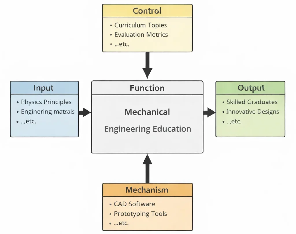
- Inputs (Left): Fundamental physical principles, raw empirical load data, multiaxial stress states, operational duty cycles, and real-world system boundary conditions.
- Controls (Top): Washington Accord/EUR-ACE accreditation frameworks, ISO/ASME/ASTM engineering standards, safety factors (SF), geometric dimensioning & tolerancing (GD&T), and sustainability mandates.
- Mechanisms (Bottom): High-performance computing nodes, finite element solvers (FEA/CFD), metrology laboratories, additive/subtractive tooling, and cyber-physical telemetry testbeds.
- Outputs (Right): Validated mechanical architectures, certified safety-critical components, closed-loop control algorithms, verified thermal-fluid balances, and practice-ready engineering leadership.
Mechanical Engineering Curricular Specializations
Select any foundational pillar below to access dedicated derivations, computational tools, and deep-dive practice modules within the Prep4Uni Mechanical Engineering cluster:
Mechanical Engineering (Curricular Hub)
Central foundation integrating energy conservation, machine kinematic synthesis, material limits, and dynamic control.
Automotive Engineering
Applies core mechanical thermodynamics, chassis kinematics, and structural impact mechanics to vehicle design.
Biomechanical Engineering
Translates mechanical stress, continuum mechanics, and kinematic linkages into prosthetic and human biological systems.
Control Systems in Mechanical Engineering
Closes the loop on mechanical systems using sensors, actuators, and dynamic state-space controllers.
Fluid Mechanics and Hydraulics
Governs internal and external momentum transport, piping hydraulic losses, and Navier-Stokes boundary flows.
Manufacturing and Production Engineering
Transforms theoretical CAD models into real products via machining, forming, additive processes, and metrology.
Mechanical Design and CAD
Executes geometric dimensioning, parametric feature modeling, and structural assembly synthesis in digital space.
Nanotechnology and Advanced Materials
Engineers micro- and nano-scale material grain boundaries, nanocomposites, and thermal barrier enhancements.
Robotics and Automation in Mechanical Engineering
Combines mechanical linkage dynamics with multi-axis trajectory planning and industrial automation.
Solid Mechanics: Stress, Strain & Structural Analysis
Analyzes elastic and plastic stress distributions, Mohr’s circle transformations, and structural failure criteria.
Thermodynamics and Heat Transfer
Quantifies energy conversion efficiency, second-law exergy destruction, and multi-mode heat transport.
Vibrations and Acoustics
Evaluates oscillatory structural responses, resonance limits, modal shapes, and acoustic noise radiation.

Deep Technical Foundations: Governing Analytical Formulations
Mechanical engineering solves physical challenges across macroscopic and microscopic scales by translating boundary-value problems into mathematical formulations. Mastery of the discipline requires rigorous fluency across solid, fluid, and thermodynamic governing frameworks.
1. Continuum Solid Mechanics & Euler-Bernoulli Beam Deflection
For an isotropic, linear-elastic structural member where transverse shear strains are negligible (L/h > 10), the flexural deflection v(x) is governed by the fourth-order ordinary differential equation:
$$EI \frac{d^4 v(x)}{dx^4} = q(x)$$where E represents Young's Modulus of Elasticity in N/m2, I is the second moment of area in m4, and q(x) is the distributed transverse load in N/m. For a simply supported prismatic beam of length L subjected to a central point load P at x = L/2, integrating under kinematic boundary conditions (v(0) = 0, v(L) = 0, M(0) = 0, M(L) = 0) yields the elastic displacement profile for 0 ≤ x ≤ L/2:
$$v(x) = \frac{P x}{48 E I} \left(3L^2 - 4x^2\right)$$Evaluating this at mid-span (x = L/2) gives the peak structural deflection (δmax):
$$\delta_{\max} = \frac{P L^3}{48 E I}$$Simultaneously, the internal bending moment is M(x) = (P · x)/2 for 0 ≤ x ≤ L/2, reaching a peak at mid-span of Mmax = (P · L)/4. The extreme outer-fiber flexural stress is calculated via the elastic section modulus Z = I/c:
$$\sigma_{\max} = \frac{M_{\max} c}{I} = \frac{P L c}{4 I}$$2. Viscous Fluid Dynamics: Incompressible Navier-Stokes Equations
The conservation of linear momentum for a Newtonian, incompressible fluid of constant dynamic viscosity μ and density ρ is expressed by the vector Navier-Stokes formulation:
$$\rho \left( \frac{\partial \mathbf{u}}{\partial t} + (\mathbf{u} \cdot \nabla) \mathbf{u} \right) = -\nabla p + \mu \nabla^2 \mathbf{u} + \rho \mathbf{g}$$paired with the continuity requirement ∇ · u = 0. In internal pressurized conduits, the frictional head loss hf over span L and diameter D is quantified by the Darcy-Weisbach formulation:
$$h_f = f \cdot \frac{L}{D} \cdot \frac{v^2}{2g}$$where the Darcy friction factor f is a function of the Reynolds number Re = (ρ · v · D) / μ and relative wall roughness ε/D, transitioning from laminar behavior (f = 64/Re when Re < 2300) to fully turbulent flow governed by the implicit Colebrook-White relationship:
$$\frac{1}{\sqrt{f}} = -2 \log_{10} \left( \frac{\varepsilon / D}{3.7} + \frac{2.51}{\text{Re} \sqrt{f}} \right)$$3. Thermal Energy Conservation & Thermodynamic Cycles
The differential energy balance equation for multi-dimensional heat conduction with internal thermal generation rate per unit volume q̇g is formulated by Fourier's law combined with internal energy storage:
$$\rho c_p \frac{\partial T}{\partial t} = \nabla \cdot (k \nabla T) + \dot{q}_g$$For cyclic heat engines operating between an isothermal high-temperature source (TH) and sink (TC), the Second Law of Thermodynamics enforces the Carnot upper limit on thermal conversion efficiency (ηth):
$$\eta_{\text{th}} = \frac{W_{\text{net}}}{Q_{\text{in}}} \le \eta_{\text{Carnot}} = 1 - \frac{T_C}{T_H}$$Contemporary Computational Paradigms in Modern Practice
Modern engineering design has moved beyond purely empirical testing or uncoupled numerical solvers. Contemporary mechanical workflows operate within coupled digital frameworks that merge physical conservation laws with high-speed digital architectures:
Physics-Informed Neural Networks (PINNs)
By embedding partial differential equations (such as the Navier-Stokes or Biharmonic elasticity equations) directly into deep learning loss functions (Ltotal = Ldata + λLPDE), PINNs solve complex inverse problems and characterize non-destructive material degradation with sparse experimental sensor data.
Fourier Neural Operators (FNOs)
Parametric PDE solvers operating in Fourier space map entire continuous input function fields to full solution spaces. FNOs execute turbulent flow CFD evaluations and nonlinear thermal evaluations up to three orders of magnitude faster than traditional fine-mesh numerical solvers, making them ideal for rapid iterative generative design.
Discrete-Event Digital Twins & Telemetry
Industrial mechanical systems combine physical components with real-time operational models. Onboard IoT vibration, strain, and temperature telemetry continually update reduced-order models (ROMs) via Extended Kalman Filtering to execute predictive failure modeling and dynamic fatigue lifecycle tracking.
Systems Engineering Trade-off Matrix
Every mechanical engineering decision involves managing conflicting requirements. The matrix below outlines fundamental design strategies, their benefits, operational risks, and industry-standard mitigations:
| Design / System Strategy | Primary Engineering Advantage | Bottlenecks & Failure Modes | Mitigation & Control Strategy |
|---|---|---|---|
| High-Yield Thin-Walled Structures | Substantial mass reduction; optimizes specific strength (σy / ρ); minimizes energy consumption in automotive/aerospace systems. | Heightened vulnerability to elastic buckling, localized crippling, reduced second moment of area (I), and accelerated high-cycle vibration fatigue. | Incorporate internal stiffening ribs; use topology optimization; perform nonlinear eigenvalue buckling analysis with safety factor SF ≥ 2.0. |
| Monolithic Additive Manufacturing (AM) | Eliminates fasteners, seals, and braze joints; enables complex internal conformal cooling channels and consolidated multi-part assemblies. | Anisotropic grain structures along build orientations; residual tensile stresses; micro-voids; severe surface roughness acting as fatigue stress risers. | Execute Hot Isostatic Pressing (HIP) heat treatments; apply abrasive flow surface polishing; orient critical principal stress vectors along build planes. |
| High-Compression Thermodynamic Cycles | Maximizes thermal conversion efficiency (ηth) via elevated expansion ratios; compact power-density footprints. | Severe thermal-mechanical creep; rapid thermal barrier coating (TBC) spallation; elevated NOx emissions due to high peak temperatures. | Deploy single-crystal nickel-based superalloys with internal serpentine cooling paths; use ceramic matrix composites (CMCs) and advanced closed-loop lean burn controls. |
| Active Cyber-Physical Feedback Control | Compensates for structural deflections and dynamic disturbances in real time; enables flexible, ultra-lightweight structural configurations. | Actuator saturation; sensor noise injection; time-delay phase lag driving the closed-loop system into catastrophic resonance or instability. | Design robust H∞ controllers with conservative gain/phase margins; implement physical mechanical fail-safes (end-stops, dampers) and dual-redundant bus architectures. |
Cross-Sector Industrial Case Studies
Aerospace Propulsion
Turbofan engine high-pressure turbine blades operate in gas temperatures exceeding 1700 K—well above the melting point of bare nickel alloys. Mechanical engineers solve this by designing intricate internal film-cooling channels and applying yttria-stabilized zirconia (YSZ) thermal barrier coatings.
Electric Mobility
Battery enclosures in electric vehicles must serve as structural shear panels during high-g collisions while isolating hundreds of lithium-ion cells from thermal runaway. This requires balanced crashworthiness design, die-cast aluminum alloys, and integrated liquid cold-plate heat exchangers.
Precision Semiconductor Tools
Photolithography wafer steppers demand sub-nanometer positioning at dynamic accelerations exceeding 10g. Mechanical engineers use magnetically levitated planar stages, Zerodur low-expansion glass ceramics, and active vibration isolation tables.
Offshore Wind Turbines
Turbine blades over 100 meters in length encounter cyclic aeroelastic flutter, gravitational fatigue, and harsh salt-spray corrosion. Engineers use carbon-glass hybrid composite laminates, passive bend-twist coupling, and tuned mass dampers inside the nacelle.
Interactive Simulation: Euler-Bernoulli Elastic Beam Bending
Evaluate real-time structural deflection and internal moment distributions under concentrated transverse loading. This simulation models a simply supported beam with user-selected structural parameters, applying Euler-Bernoulli beam theory via our verified zero-crash canvas architecture.
Euler-Bernoulli Elastic Flexure Engine
STATUS: ACTIVE SOLVERFrequently Asked Questions: Curricular & Professional Standards
1. What distinguishes the Washington Accord engineering standard from basic technology diplomas?
2. How do modern mechanical engineers balance analytical derivations with commercial FEA/CFD packages?
3. Why is Euler-Bernoulli beam theory valid only under specific slenderness ratios?
4. What role does Geometric Dimensioning & Tolerancing (GD&T) play in machine design?
5. How does the von Mises yield criterion differ from the Maximum Shear Stress (Tresca) criterion?
6. How does the First Law differ from the Second Law of Thermodynamics in energy systems design?
7. What is the difference between finite element analysis (FEA) and finite volume method (FVM)?
8. How do digital twins transition from reactive monitoring to predictive lifecycle maintenance?
Student Practice & Accreditation Assessment Modules
Section 1: Conceptual Knowledge Self-Assessment
Q1: Explain why a circular cross-section is mathematically superior for pure torsional transmission compared to a thin rectangular section.
Q2: Formulate the physical significance of the Reynolds number in dynamic fluid regimes.
Q3: Why does adding cooling fins beyond a critical thickness or length reduce, rather than increase, total heat rejection?
Q4: How do the Soderberg, Goodman, and Gerber fatigue criteria differ when designing against fluctuating cyclic loads?
- Soderberg: Connects endurance limit Se to yield strength Sy: $$\frac{\sigma_a}{S_e} + \frac{\sigma_m}{S_y} = 1$$ It provides the most conservative safety margins, guarding against both fatigue and static yielding.
- Modified Goodman: Connects endurance limit Se to ultimate tensile strength Sut: $$\frac{\sigma_a}{S_e} + \frac{\sigma_m}{S_{ut}} = 1$$ This is the standard industrial baseline for ductile metals under cyclical tensile stress.
- Gerber: Uses a parabolic relationship connecting Se to Sut: $$\frac{\sigma_a}{S_e} + \left(\frac{\sigma_m}{S_{ut}}\right)^2 = 1$$ It models real experimental fatigue failure data closely, but provides smaller safety margins when positive mean stresses are present.
Q5: Why is the thermal boundary layer thicker than the velocity boundary layer when the Prandtl number is less than unity?
Q6: Differentiate between ductile and brittle fracture modes under high-strain impact loading.
Q7: Why do underdamped mechanical vibrating systems experience maximum resonant displacement below the undamped natural frequency?
Q8: What physical mechanisms cause cavitation in centrifugal pumps, and how does Net Positive Suction Head (NPSH) prevent it?
Section 2: Analytical & Scenario-Based Case Studies
Scenario: A 120-mm-diameter solid AISI 4340 alloy steel driveshaft on an auxiliary steam turbine failed catastrophically after 14 months of operation[cite: 1]. Fracture analysis revealed beach marks originating at a 1.5-mm shoulder radius fillet, indicating progressive fatigue that transitioned to fast brittle fracture across 65% of the cross-section[cite: 1].
Engineering Evaluation:
1. Stress Concentration: The sharp transition fillet generated a localized geometric stress concentration factor (Kt ≈ 2.4), which raised localized cyclical stresses well above the alloy's endurance limit (Se)[cite: 1].
2. Multiaxial Loading: The shaft experienced steady torsional shear from electrical generation combined with fully reversed cyclic bending caused by slight bearing misalignment[cite: 1]. This produced an alternating multiaxial stress state[cite: 1]:
$$\sigma_{a,\text{eq}} = \sqrt{\sigma_a^2 + 3\tau_a^2}$$
Corrective Engineering Action: Redesign the shoulder fillet radius from 1.5 mm to 6.0 mm (reducing Kt to 1.35), introduce deep-roll burnishing to generate protective compressive residual surface stresses, and install laser-aligned hydrodynamic bearings monitored by online spectral vibration sensors[cite: 1].
Scenario: During ground-strike testing of an electric vehicle pack, road debris penetrated an underbody aluminum skid plate, puncturing an internal 2170 cylindrical cell[cite: 2]. Within 45 seconds, the cell triggered an exothermic cascade that compromised adjacent cells through conductive thermal runaway[cite: 2].
Engineering Evaluation:
1. Structural Impact Resistance: The original single-layer 6000-series aluminum base lacked adequate dynamic shear resistance under high-velocity localized impacts[cite: 2].
2. Thermal Isolation: The cell-to-cell structural bonding adhesive had high thermal conductivity, which allowed rapid propagation of a 900°C thermal wave to neighboring cells[cite: 2].
Corrective Engineering Action: Upgrade to a dual-phase ultra-high-strength steel (UHSS) sandwich baseplate with an energy-absorbing honeycomb core[cite: 2]. Isolate individual cells with aerogel insulation pads (k ≈ 0.018 W/(m·K)), and route rapid-discharge directional pyrotechnic venting channels through the pack roof[cite: 2].
Scenario: Following a grid-trip event, an emergency shut-off butterfly valve on an 800-meter welded steel penstock closed in 1.2 seconds[cite: 2]. The sudden deceleration caused a hydraulic shock wave that ruptured an upstream welded expansion joint, flooding the turbine hall[cite: 2].
Engineering Evaluation:
1. Wave Travel Mechanics: The acoustic pressure wave speed through the water-filled elastic steel pipe was[cite: 2]:
$$a = \sqrt{\frac{K / \rho}{1 + (K/E)(D/t)}} \approx 1050 \text{ m/s}$$
The critical pipeline reflection period was 2L/a = 2(800)/1050 ≈ 1.52 s[cite: 2]. Because the valve closed in tc = 1.2 s < 2L/a, the event behaved as an abrupt closure, generating a Joukowsky pressure surge[cite: 2]:
$$\Delta p = \rho \cdot a \cdot \Delta v$$
With an initial flow velocity change of Δv = 4.2 m/s, the surge pressure was[cite: 2]:
$$\Delta p = 1000 \cdot 1050 \cdot 4.2 = 4.41 \times 10^6 \text{ Pa} = 4.41 \text{ MPa} \quad (\approx 450 \text{ m of added head})$$
This transient load exceeded the yield strength of the aged welded joint[cite: 2].
Corrective Engineering Action: Reprogram the valve actuator with a two-stage closure profile (80% closure over 12 seconds, followed by slow final seating over 8 seconds), and install a surge tank near the turbine inlet to absorb fluid momentum[cite: 2].
Scenario: During high-altitude engine certification flights, titanium integrally bladed rotors (blisks) on a low-pressure compressor experienced blade-tip micro-cracking within 85 flight hours.
Engineering Evaluation:
Unlike traditional slotted blade roots that dissipate vibration through frictional sliding, monolithic blisks have near-zero mechanical damping. At transonic speeds, periodic shock-wave oscillations on the suction surfaces coupled with the first torsional structural mode of the blades. This aeroelastic flutter drove rapid cyclic strain accumulation and high-cycle fatigue failure.
Corrective Engineering Action: Modify blade geometry to introduce intentional aerodynamic sweep (disrupting coherent spanwise shock oscillations), and apply ring dampers inside the blisk rim to reintroduce friction-based damping.
Scenario: A reusable liquid oxygen/methane rocket engine prototype developed microscopic coolant-channel cracks after four static hot-fire cycles, allowing fuel to leak into the expansion plume.
Engineering Evaluation:
The copper-alloy (GRCop-84) inner liner undergoes extreme thermal gradients across its 0.8-mm hot-gas wall (outer face ∼ 850 K, coolant-wetted face ∼ 180 K). The constrained thermal expansion generates cyclic compressive plastic strain during firing, followed by tensile residual stresses upon shutdown. This rapid thermal cycle caused low-cycle thermal fatigue cracking.
Corrective Engineering Action: Electroplate a 50-μm ductile nickel barrier layer within the milled cooling channels, optimize channel aspect ratios to reduce peak wall temperatures, and introduce a fuel-film cooling layer along the nozzle interior boundary layer.
Scenario: A variable-speed centrifugal water chiller installed on a hospital rooftop experienced severe vibration and pipe flange cracking whenever the motor modulated to 48.5 Hz (2910 RPM).
Engineering Evaluation:
Modal tap testing identified a natural frequency of the chiller's structural base frame and discharge piping at 48.8 Hz, with a low damping ratio (ζ ≈ 0.012). When the motor operated near 48.5 Hz, rotational unbalance excited the frame into resonance, driving vibration amplitudes above 18 mm/s RMS (exceeding ISO 10816 limits).
Corrective Engineering Action: Stiffen the structural steel base with diagonal gusset plates (raising the natural frequency to 61 Hz, well outside the operating range), install elastomeric vibration isolation pads with ζ ≥ 0.08, and program a frequency exclusion band (46–51 Hz) into the variable frequency drive (VFD).
Scenario: A subsea locking mandrel forged from high-strength martensitic stainless steel failed after three years of deepwater service, despite operating well within its static design yield limits.
Engineering Evaluation:
Failure occurred through Chloride-Induced Stress-Corrosion Cracking (CISCC). The mandrel operated under sustained tensile preload stress in a high-chloride marine environment, while cathodic protection produced hydrogen embrittlement at localized pit sites. Crack growth followed stress-corrosion mechanisms governed by:
$$K_I \ge K_{\text{ISCC}}$$
Corrective Engineering Action: Replace the material with cold-worked Inconel 718 (a nickel-chromium superalloy with superior CISCC immunity), lower the bolt torque spec to keep sustained tensile stresses below 40% of yield, and apply thermally sprayed aluminum coatings to improve galvanic protection.
Section 3: Step-by-Step Quantitative Worked Examples
Problem Statement: A simply supported structural steel wide-flange beam spans L = 8.0 m and supports a central hoist load of P = 45 kN. The cross-section has a second moment of area I = 1.25 × 10⁻⁴ m4, a total depth 2c = 0.40 m (c = 0.20 m), and Young's Modulus E = 200 × 109 N/m2. Calculate:
(a) The maximum mid-span deflection (δmax) in millimeters.
(b) The peak flexural bending stress (σmax) at the outer fibers in MPa.
(c) The structural safety factor (SF) if the steel yield strength is σy = 250 MPa.
Problem Statement: A marine diesel engine delivers Pmech = 450 kW at an operational speed of N = 1800 RPM to a solid steel driveshaft of length L = 3.5 m and radius r = 0.04 m (diameter D = 0.08 m). The material shear modulus is G = 78 GPa. Calculate:
(a) The operational torque (T) transmitted by the shaft.
(b) The peak surface shear stress (τmax) in MPa.
(c) The total torsional elastic twist (θ) across the shaft in degrees.
Problem Statement: Water at 20°C (density ρ = 998 kg/m3, dynamic viscosity μ = 1.002 × 10⁻³ Pa·s) flows through a horizontal commercial steel pipe (diameter D = 0.15 m, absolute roughness ε = 0.045 mm) of length L = 120 m at a volumetric flow rate Q = 0.055 m3/s[cite: 3]. Given acceleration due to gravity g = 9.81 m/s2[cite: 3]:
(a) Determine the mean flow velocity (v) and Reynolds number (Re)[cite: 3].
(b) Determine the Darcy friction factor (f) using the Swamee-Jain explicit approximation[cite: 3].
(c) Calculate total frictional head loss (hf) and the required pumping power (Ppump) assuming 100% pump efficiency[cite: 3].
Problem Statement: An industrial furnace wall consists of an inner refractory firebrick layer (L1 = 0.12 m, k1 = 1.4 W/(m·K)) and an outer mineral wool insulation layer (k2 = 0.05 W/(m·K)). The furnace interior surface is maintained at Thot = 920°C (1193.15 K), and the ambient factory air is at T∞ = 25°C (298.15 K) with an external natural convection coefficient hconv = 12 W/(m2·K).
Calculate the minimum mineral wool thickness (L2) needed to keep the outer casing temperature (Tsurface) at or below 55°C (328.15 K) for personnel burn safety.
At steady state, the heat flux conducted through the wall equals the heat flux convected from the outer surface to the ambient air:
$$q'' = h_{\text{conv}} (T_{\text{surface}} - T_\infty) = (12 \text{ W/m}^2\cdot\text{K}) \cdot (55^\circ\text{C} - 25^\circ\text{C}) = 12 \cdot 30 = 360 \text{ W/m}^2$$The total thermal resistance is the sum of the conduction and external convection resistances:
$$R''_{\text{total}} = R''_{\text{firebrick}} + R''_{\text{insulation}} + R''_{\text{convection}} = \frac{L_1}{k_1} + \frac{L_2}{k_2} + \frac{1}{h_{\text{conv}}}$$Problem Statement: A thermal power plant operates between a high-temperature boiler at TH = 560°C (833.15 K) and a condenser cooled by a river at TC = 22°C (295.15 K)[cite: 4]. The system consumes fuel input power Q̇in = 120 MW and produces a net mechanical work output Ẇnet = 44.5 MW[cite: 4]. Calculate:
(a) The theoretical maximum Carnot thermal efficiency (ηCarnot)[cite: 4].
(b) The actual first-law thermal conversion efficiency (ηactual)[cite: 4].
(c) The Second-Law efficiency (ηII) of the plant[cite: 4].
(d) The rate of waste heat rejection (Q̇out) discharged into the river[cite: 4].
Problem Statement: An industrial compressor of total mass m = 850 kg is mounted on an elastomeric foundation system with an equivalent stiffness k = 3.2 × 10⁶ N/m and a viscous damping coefficient c = 8.5 × 10³ N·s/m. Calculate:
(a) The undamped natural angular frequency (ωn) in rad/s and cyclic frequency (fn) in Hz.
(b) The critical damping coefficient (ccr) and dimensionless damping ratio (ζ).
(c) The damped natural frequency (fd) in Hz.
(d) The resonant excitation frequency (fr) that generates peak displacement amplitude.