
- Machine Element Synthesis: Formulate stress tensors, von Mises distortion energy criteria, ASME elliptic and modified Goodman fatigue boundaries, and bolted joint stiffness fractions.
- Digital Prototyping & Simulation: Execute parametric solid modeling, kinematic assembly mate solving, and integrated FEA boundary discretization for structural deflection and stress concentration.
- Production Translation & DFMA: Implement Geometric Dimensioning & Tolerancing (ASME Y14.5), Design for Manufacturing and Assembly part consolidation, and Model-Based Definition (MBD) standards.
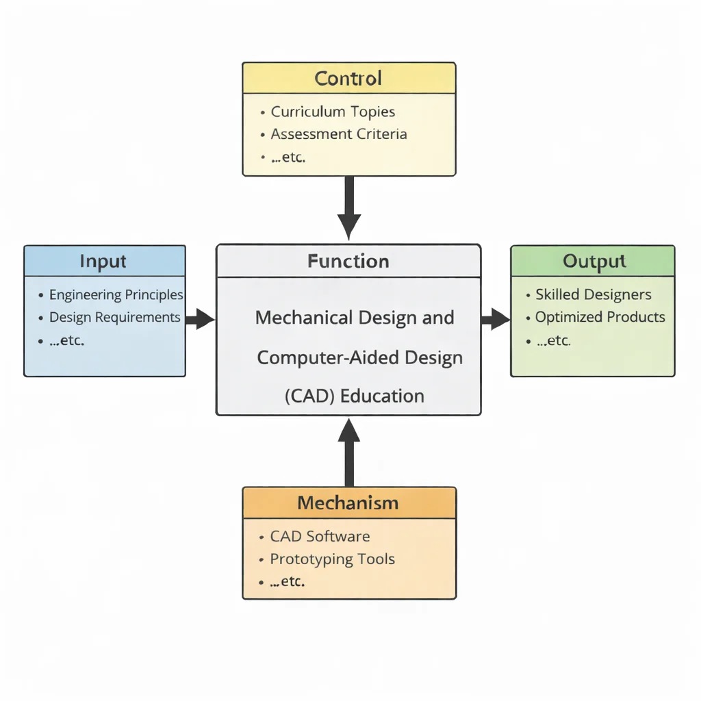
- Inputs (Left): Functional mechanical specifications, operational load envelopes, kinematic degrees of freedom, candidate material properties, and space-claim geometric boundaries.
- Controls (Top): Washington Accord/EUR-ACE engineering benchmarks, ASME Y14.5 GD&T drafting standards, ISO 12100 machine safety directives, and target Factor of Safety (FOS) guidelines.
- Mechanisms (Bottom): Parametric 3D solid modeling kernels (Parasolid, ACIS), FEA structural solvers, generative topology optimization engines, CMM inspection tools, and rapid prototyping additive cells.
- Outputs (Right): Validated 3D digital master assemblies, certified manufacturing drawing packs with datum-referenced tolerances, kinematic motion studies, and industry-ready mechanical design engineers.
Mechanical & Manufacturing Engineering Curriculum Cluster
Select any foundational pillar below to explore related modules across the PREP4UNI.ONLINE Mechanical Engineering series:
Mechanical Engineering
Translates physical force balances, kinematics, and energy constraints into manufactured mechanical parts and systems.
Automotive Engineering
Coordinates digital packaging envelopes for multi-link suspensions, front-impact crash structures, and battery pack enclosures.
Biomechanical Engineering
Converts segmented patient CT scans into organic NURBS surface models for custom knee and hip arthroplasty implants.
Control Systems in Mechanical Engineering
Integrates servomotor enclosures, encoder mounting brackets, and wiring harness corridors within digital CAD assemblies.
Fluid Mechanics and Hydraulics
Models smooth flow-split manifolds, aerodynamic aerofoil surface cross-sections, and pump impeller blade profiles.
Manufacturing and Production Engineering
Applies ASME Y14.5 GD&T datum feature symbols to ensure fitment stack-up tolerances match CNC shop capabilities.
Mechanical Design and CAD
Parametric 3D solid modeling, mechanical machine components, kinematic assembly simulation, and digital product twins.
Nanotechnology and Advanced Materials
Implements generative gyroid and triply periodic minimal surface (TPMS) infill lattices for light-weighting components.
Robotics and Automation in Mechanical Engineering
Synthesizes Denavit-Hartenberg coordinate frames, harmonic drive gear interfaces, and multi-axis joint reach envelopes.
Solid Mechanics: Stress, Strain & Structural Analysis
Applies mesh convergence and evaluates von Mises equivalent stress distributions to prevent plastic yielding under load.
Thermodynamics and Heat Transfer
Sizes compact finned heat exchangers, internal cooling jacket channels, and insulation jacket layers in 3D assemblies.
Vibrations and Acoustics
Performs digital modal eigen-frequency extraction on machine frames to prevent resonance with operational rotating shafts.

Deep Technical Foundations: Analytical Machine Design & Computational Mechanics
Engineering design couples continuum mechanics with empirical failure limits. Rather than relying on simple nominal calculations, robust CAD design requires evaluating multi-axial stress states, cyclical fatigue degradation, and joint stiffness compliance.
1. Multi-Axial Static Yield Criteria: Von Mises Distortion Energy
In ductile machine components subject to combined bending, axial tension, and torsion, static yielding occurs when the distortion strain energy reaches the yield threshold in uniaxial tension. For a 2D plane stress state (σx, σy, τxy), the equivalent von Mises stress σvm is formulated as:
$$\sigma_{vm} = \sqrt{\sigma_x^2 - \sigma_x \sigma_y + \sigma_y^2 + 3\tau_{xy}^2}$$The static Factor of Safety (ns) relative to material tensile yield strength Sy is governed by:
$$n_s = \frac{S_y}{\sigma_{vm}} \ge 1.0$$2. Dynamic Fatigue Failure: Modified Goodman & ASME Elliptic Criteria
Machine elements under alternating cyclic loads experience fatigue crack propagation below static yield limits. Resolving alternating stress σa and mean stress σm against endurance limit Se and ultimate tensile strength Sut, the Modified Goodman design boundary satisfies:
$$\frac{\sigma_a}{S_e} + \frac{\sigma_m}{S_{ut}} = \frac{1}{n_f}$$where nf is the fatigue Factor of Safety. The unnotched endurance limit is modified using Marin correction factors: Se = ka · kb · kc · kd · ke · S'e, accounting for surface finish, size, load type, temperature, and geometric stress concentration Kf = 1 + q(Kt − 1).
3. Bolted Joint Compliance & Preload Clamping Mechanics
Preloaded threaded fasteners form an elastic clamping system where bolt tension Fi compresses clamped member plates. The joint stiffness constant C is defined by bolt stiffness kb and member stiffness km:
$$C = \frac{k_b}{k_b + k_m}$$When an external tensile service load P acts on the joint, the resulting total tensile bolt force Fb and residual compressive clamping force Fm are distributed as:
$$F_b = F_i + C \cdot P, \qquad F_m = F_i - (1 - C) \cdot P$$To prevent joint separation and maintain gasket hermetic sealing, design mandates Fm > 0, requiring initial tightening preload Fi > (1 − C)P.
Contemporary Computational Paradigms in Mechanical CAD
Design engineering has moved from passive geometric drawing tools to automated generative synthesis, neural physics accelerators, and connected digital threads:
AI Generative Topology Optimization
Generative design algorithms employ SIMP (Solid Isotropic Material with Penalization) mathematical methods to redistribute material across complex 3D design domains. Driven by target stress, stiffness, and additive or 5-axis manufacturing constraints, the solver creates high-stiffness organic structures with 30–50% less weight.
PINNs for Rapid Structural Stress Evaluation
Physics-Informed Neural Networks integrate the 3D Navier-Cauchy equilibrium equations directly into training loss functions. PINNs predict structural stress concentration factors across parametric CAD variations in milliseconds, providing interactive design feedback without waiting for lengthy FEA meshing.
Model-Based Definition (MBD) & Digital Thread
MBD integrates 3D Product and Manufacturing Information (PMI), GD&T, surface finishes, and bill of materials directly into the native 3D solid model (STEP AP242). This establishes an unbroken digital thread that feeds CMM coordinate inspection routines and automated CAM toolpaths without ambiguous 2D paper drawings.
Systems Engineering Trade-off Matrix
Mechanical design requires balancing stiffness, structural mass, fatigue life, machining tolerances, and assembly complexity:
| Design Strategy / Architecture | Primary Engineering Advantage | Bottlenecks & Failure Modes | Mitigation & Control Strategy |
|---|---|---|---|
| Generative Lattice Topology Optimization | Reduces component mass by 40–60%; optimizes specific structural stiffness along exact load paths. | High surface roughness (Ra 12–25 μm) in additive builds triggers notch sensitivity and poor high-cycle fatigue life. | Apply post-build Hot Isostatic Pressing (HIP); machine critical mating flanges and bore shoulders with high-speed CNC finishing. |
| Tight Dimensional Tolerancing (ISO IT5–IT6) | Ensures precise mechanical alignment; minimizes backlash in high-speed gearboxes; maximizes seal longevity. | Manufacturing costs escalate exponentially; requires slow multi-pass grinding, lapping, and 100% CMM inspection. | Perform statistical tolerance stack-up analysis (RSS/Monte Carlo); apply GD&T bonus tolerance using Maximum Material Condition (MMC). |
| High Fastener Preload Clamping (Fi ≈ 0.75 Sp At) | Prevents joint separation under high cyclic service loads; minimizes alternating stress amplitude experienced by the bolt. | Overtorquing risks yield stripping of internal threads; high preload promotes stress corrosion cracking in aggressive environments. | Use calibrated torque-angle tightening or ultrasonic bolt elongation measurement; ensure thread engagement length Le ≥ 1.5 D. |
| DFMA Part Consolidation | Replaces complex multi-piece bolted assemblies with unified unibody casting or molding; lowers assembly labor. | Increased tooling die cost; complex single parts are difficult and expensive to service or replace when locally worn. | Incorporate replaceable wear inserts, press-fit bronze bushings, and modular sacrificial interface brackets at high-wear locations. |
Cross-Sector Industrial Case Studies
Aerospace Jet Engine Pylon Brackets
Titanium engine suspension links undergo combined multi-axis thrust, aerodynamic buffet, and thermal gradients up to 350°C. Parametric CAD packages interface with damage tolerance fracture mechanics solvers, verifying that critical crack growth rates remain detectable between scheduled major airframe maintenance cycles.
Automotive Drive Axle & CV Joint Design
Constant-velocity joint splines are optimized in CAD to balance torque transmission against contact stress wear. Induction hardening profiles are modeled to provide a hard, wear-resistant outer case (58–62 HRC) while preserving a ductile core to absorb sudden shock-load driveline reversals.
Robotic Harmonically Geared Manipulators
High-precision industrial robotic joints integrate strain wave gearing modeled with zero backlash. Finite element tooth contact analysis (FE-TCA) optimizes flexible spline tooth crowning to minimize kinematic transmission error and ensure positioning repeatability within ±0.01 mm.
Subsea High-Pressure Valve Bodies
Deepwater subsea trees operating at 15,000 psi (103 MPa) utilize forged nickel-chromium superalloy valve bodies. CAD finite element models simulate autofrettage residual compressive stress fields to ensure reliable fatigue life under cyclic wellhead shut-ins.
Interactive Simulation: CAD Structural Beam Stress & Deflection Engine
Evaluate real-time flexural bending stress, neutral axis moment of inertia, and mid-span beam deflection for a simply supported machine element under an interactive point load using our verified zero-crash canvas architecture.
Interactive CAD Structural FEA & Deflection Simulator
STATUS: ACTIVE FEA SOLVERSimulates bending stress and mid-span flexural deflection for a rectangular structural beam (width b = 40 mm, steel E = 210 GPa) under a concentrated central load.
Frequently Asked Questions: Mechanical Design & CAD Workflows
1. What distinguishes parametric modeling from direct modeling in engineering CAD?
2. How does the von Mises distortion energy theory predict yield failure under combined stress?
3. Why is Geometric Dimensioning and Tolerancing (GD&T) superior to coordinate ± tolerancing?
4. What role does joint stiffness ratio (C) play in preventing bolt fatigue failure?
5. How does CAD-integrated Finite Element Analysis (FEA) handle stress singularities?
6. What is the fundamental difference between bottom-up and top-down CAD assembly modeling?
7. How does Design for Manufacturing and Assembly (DFMA) lower product realization costs?
8. How does Model-Based Definition (MBD) eliminate 2D paper drawings in digital manufacturing?
Student Practice & Accreditation Assessment Modules
Section 1: Interactive Knowledge Self-Assessment
Q1: Explain why the Modified Goodman fatigue boundary is preferred over the Soderberg line in ductile machine design.
Q2: Differentiate between clearance, transition, and interference fits according to ISO / ANSI standards.
- Clearance Fit (e.g., H7/g6): The hole is always larger than the shaft, ensuring free relative rotation or axial sliding with guaranteed positive clearance.
- Transition Fit (e.g., H7/k6): Tolerance zones overlap; the assembly may yield either slight clearance or slight interference, ideal for precise locating without play.
- Interference Fit (e.g., H7/p6): The shaft is always larger than the hole, requiring press-fitting or thermal shrink-fitting to transmit friction torque without keys.
Q3: Formulate why geometric stress concentration factor (Kt) is higher for small fillet radii on stepped shafts.
Q4: How does the Maximum Material Condition (MMC) modifier generate "bonus tolerance" in GD&T?
Q5: Why is through-bolt clamping preferred over tapped blind-hole fastening in cyclic machine structures?
Q6: What causes shear tear-out failure in mechanical bolted lap joints?
Q7: Differentiate between h-adaptive and p-adaptive mesh refinement in structural FEA solvers.
Q8: Formulate the relationship between transmitted shaft torque, rotational speed, and required shaft diameter.
Section 2: Analytical & Scenario-Based Case Studies
Scenario: An industrial conveyor drive shaft (AISI 1045 steel, Sut = 620 MPa) fractured catastrophically after 420 hours of operation (approximately 4.5 × 10⁷ cycles). Beach marks on the fracture surface indicated reverse-bending fatigue initiation at a shoulder step transition between bearing seat (Ø60 mm) and coupling seat (Ø45 mm).
Engineering Evaluation:
1. CAD Modeling Defect: The 2D detail drawing specified a sharp fillet radius r = 0.5 mm to clear a standard bearing chamfer.
2. Stress Concentration: The geometric ratios D/d = 60/45 = 1.33 and r/d = 0.5/45 = 0.011 produced a theoretical stress concentration factor:
$$K_t \approx 2.45$$
With fatigue notch sensitivity q = 0.82, dynamic fatigue notch factor reached Kf = 1 + 0.82(2.45 − 1) = 2.19. This elevated alternating bending stress above the corrected endurance limit (Se = 185 MPa), initiating micro-cracks under normal operating torque.
Corrective Engineering Action: Redesign the step shoulder with an undercut relief groove (DIN 509 Form F, radius r = 3.0 mm), lowering Kt to 1.38. Insert a precision ground spacer ring to seat the bearing chamfer against a flat face while keeping the transition radius large.
Scenario: A planetary gearbox for an aerospace actuator seized during high-temperature qualification testing at 85°C. Disassembly showed deep galling on the steel planet carrier shaft and cracked bronze journal bushings press-fitted into the aluminum housing.
Engineering Evaluation:
1. Differential Expansion: Aluminum has a thermal expansion coefficient (αAl ≈ 23 × 10−6 /°C) nearly double that of alloy steel (αSteel ≈ 12 × 10−6 /°C).
2. Interference Loss: At 85°C (ΔT = +65°C), the aluminum housing bore expanded faster than the bronze bushing, causing loss of retention press-fit. Concurrently, axial expansion closed internal shaft end-play clearances to zero:
$$\Delta L_{\text{interference}} = L_0 \cdot \Delta\alpha \cdot \Delta T \gt \text{Clearance}$$
generating high axial compressive clamping that sheared the bronze bushing flanges.
Corrective Engineering Action: Perform coupled thermal-structural FEA across the full operating range (−40°C to +100°C). Redesign bearing arrangements with a fixed deep-groove ball bearing at one end and a floating cylindrical roller bearing at the opposite end to absorb axial thermal expansion.
Scenario: A class 600 bolted bonnet valve operating at 40 bar steam pressure suffered gasket blowout during plant pressure testing when internal line pressure surged by 15%.
Engineering Evaluation:
The joint used 8 Grade 8.8 M16 bolts. Assembly technicians used un-calibrated impact wrenches, achieving average preload Fi = 32 kN per bolt. The total internal pressure separation force was:
$$P_{\text{total}} = P_{\text{pressure}} \cdot A_{\text{bonnet}} = 4.6 \times 10^6 \text{ Pa} \cdot 0.045 \text{ m}^2 = 207 \text{ kN}$$
Divided across 8 bolts, external service load was P = 25.88 kN per bolt. Joint stiffness ratio was C = 0.22. Residual member clamping force was:
$$F_m = F_i - (1 - C)P = 32 - (1 - 0.22)(25.88) = 32 - 20.19 = 11.81 \text{ kN}$$
During the 15% pressure spike, Fm dropped to zero, allowing the spiral-wound gasket to decompress and blow out.
Corrective Engineering Action: Upgrade to Grade 10.9 fasteners tightened via calibrated torque-angle control to achieve initial preload Fi = 68 kN (70% of bolt proof load), ensuring positive gasket seating stress under all transient pressure conditions.
Scenario: A satellite solar array deployment linkage stalled at 78 degrees of deployment during thermal-vacuum testing, failing to reach its locked 180-degree configuration.
Engineering Evaluation:
1. CAD Mate Discrepancy: The CAD assembly model assumed ideal nominal link lengths without geometric tolerancing.
2. Tolerance Stack-Up: Hole location tolerances (±0.15 mm) on the carbon-composite hinge clevises accumulated along the 4-bar kinematic loop. At 78 degrees, the linkage approached a kinematic toggle singular position where transmission angle dropped below 15 degrees:
$$\mu_{\text{trans}} \lt 15^\circ$$
Friction in the pin joints combined with worst-case link length stack-up created mechanical self-locking.
Corrective Engineering Action: Re-synthesize the 4-bar linkage geometry in CAD to maintain transmission angles μ ≥ 40° throughout deployment. Apply GD&T profile-of-a-surface controls to hinge clevises and incorporate spring-loaded over-center assist linkages.
Scenario: An open-face titanium centrifugal compressor impeller experienced blade tip high-cycle fatigue fractures after 120 operating hours in an industrial refrigeration chiller.
Engineering Evaluation:
Modal analysis of the CAD solid model revealed a second blade chordwise bending natural mode at f2 = 3450 Hz. Operating at N = 13,800 RPM, the impeller ran inside a stationary diffuser housing with 15 vaned nozzles. The aerodynamic vane passing frequency was:
$$f_{\text{vane}} = \frac{N \cdot z_{\text{vanes}}}{60} = \frac{13{,}800 \cdot 15}{60} = 3450 \text{ Hz}$$
The aerodynamic pressure pulses matched the blade structural resonance mode, generating high alternating bending stresses that caused fatigue failure.
Corrective Engineering Action: Plot a Campbell diagram to decouple blade modes from engine order excitation. Thicken the blade hub root fillet and adjust back-face tapering in CAD to shift blade natural frequency to 4100 Hz (> 18% margin above excitation).
Scenario: A 4-meter structural steel tubular gantry frame bowed out of flat by 8.5 mm after welding, requiring extensive manual flame straightening and costly scrap of pre-machined linear guide rail mounting pads.
Engineering Evaluation:
The original CAD model placed large continuous fillet welds along only one side of the box-tube members. Non-uniform thermal shrinkage during cooling produced high asymmetric residual stresses across the neutral axis:
$$M_{\text{residual}} = \int \sigma_{\text{res}} \cdot y \, dA$$
This induced severe angular weld distortion along the gantry span.
Corrective Engineering Action: Redesign the weldment drawing with balanced double-sided intermittent staggered fillet welds. Sequence weld passes symmetrically around the neutral axis and specify post-weld thermal stress-relief annealing (600°C) prior to final CNC machining of guide rail mounting surfaces.
Scenario: First-stage turbine blades on an aeroderivative gas turbine suffered fir-tree root tang shear fracture during a baseload run at 1050°C gas temperature.
Engineering Evaluation:
Centrifugal pull loads on the rotating blades (≈ 45 kN per blade) were transmitted through multi-serration fir-tree root lugs. Due to broaching manufacturing tolerances on the disc rim slots, the bottom serration lug bore 65% of the total centrifugal shear load. Operating above 0.5 Tmelt, localized shear stress accelerated tertiary creep rupture according to the Larson-Miller parameter:
$$P_{\text{LM}} = T \left( C + \log t_r \right)$$
leading to tang shear failure after 1800 operating hours.
Corrective Engineering Action: Redesign the fir-tree root geometry using contact FEA with flexible compliance relief pockets to balance load share evenly across all three serration pairs. Specify single-crystal nickel superalloy casting with EDM precision slot machining.
Section 3: Step-by-Step Quantitative Worked Examples
Problem Statement: A solid round steel shaft modeled in CAD has a diameter d = 40.0 mm (0.040 m) and cantilevered length L = 0.80 m. The material is structural carbon steel with elastic modulus E = 200 GPa (200 × 109 Pa). A vertical downward point load F = 2500 N is applied at the free end. Calculate:
(a) The area moment of inertia (I) of the circular cross-section in m4.
(b) The maximum bending moment (Mmax) and maximum bending stress (σmax) occurring at the fixed root in MPa.
(c) The maximum elastic deflection (δmax) at the free end in millimeters.
Problem Statement: A solid steel drive shaft operating at rotational speed N = 1800 RPM transmits mechanical power P = 45.0 kW. The shaft has diameter d = 35.0 mm (0.035 m), active length L = 1.20 m, and shear modulus G = 80.0 GPa (80 × 109 Pa). Calculate:
(a) The steady transmitted torque (T) in N·m.
(b) The polar moment of inertia (J) in m4 and maximum torsional shear stress (τmax) in MPa.
(c) The total elastic angle of twist (θ) across the shaft length in radians and degrees.
Problem Statement: A CAD pressure vessel end-cover is fastened by a circular bolt pattern of 8 identical alloy steel bolts. The tensile stress area per bolt is At = 84.3 mm2 (84.3 × 10⁻⁶ m2), and the bolt proof strength is Sp = 640 MPa. Internal vessel pressure produces a total separating force Ftotal = 180 kN distributed equally across all 8 bolts. Calculate:
(a) The external tensile working load per bolt (Fb) in kilonewtons.
(b) The axial tensile working stress (σb) in each bolt in MPa.
(c) The static Factor of Safety (ns) against proof strength.
Problem Statement: Finite Element Analysis of a CAD mounting bracket identifies a critical surface element subject to a plane state of stress: normal stress σx = 140.0 MPa, normal stress σy = −60.0 MPa, and shear stress τxy = 55.0 MPa. The bracket is cast from ductile aluminum alloy with tensile yield strength Sy = 310 MPa. Calculate:
(a) The principal stresses (σ1, σ2) in MPa.
(b) The equivalent von Mises distortion energy stress (σvm) in MPa.
(c) The static yield Factor of Safety (ns).
Problem Statement: A CAD-modeled connecting rod operates under cyclical fluctuating tensile loading. Stress analysis reveals an alternating axial stress σa = 120.0 MPa and a steady mean stress σm = 160.0 MPa. The rod is forged from steel with ultimate tensile strength Sut = 750.0 MPa and yield strength Sy = 540.0 MPa. The fully corrected endurance limit is Se = 280.0 MPa. Calculate:
(a) The fatigue Factor of Safety (nf) using the Modified Goodman criterion.
(b) The static yield Factor of Safety (ny) against peak operating stress.
Problem Statement: An axial sub-assembly consists of an internal housing slot of nominal width A = 50.00 ± 0.15 mm containing three stacked components in series: component B = 15.00 ± 0.05 mm, component C = 20.00 ± 0.06 mm, and component D = 14.50 ± 0.04 mm. The residual axial clearance gap is G = A − (B + C + D). Calculate:
(a) The nominal clearance gap (Gnom) in mm.
(b) The minimum and maximum clearance gap using Worst-Case (linear arithmetic) analysis.
(c) The statistical 3σ gap variation using Root Sum of Squares (RSS) analysis, and evaluate whether the gap remains positive (Gmin > 0).