
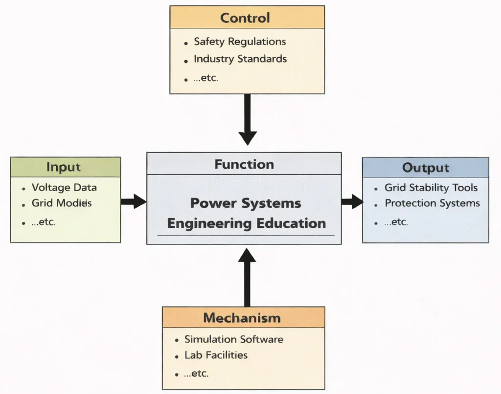
Power Systems Engineering Education is where students learn to think like guardians of a living infrastructure—the electrical grid. Using the inputs shown (voltage data and grid models), they practice reading system behaviour the way a doctor reads vital signs: what is normal, what is drifting, and what might collapse under stress. The controls in the diagram—industry standards and safety regulations—act like the “non-negotiables,” training students to design not just for performance, but for protection, compliance, and public safety. With simulation tools and hands-on laboratory work as the mechanism, learners rehearse disturbances, faults, and operating scenarios until they can respond with calm engineering logic. What comes out, as the diagram indicates, are concrete competencies: the ability to build and evaluate stability solutions, and to design protection schemes that keep power systems dependable when the real world becomes messy.
Power Systems Engineering is at the core of modern civilization’s energy infrastructure, focusing on the generation, transmission, distribution, and management of electrical power. As a specialized field within Electrical and Electronic Engineering, it addresses challenges such as load balancing, energy efficiency, and system resilience. Innovations in Embedded Systems and Microelectronics have enabled the real-time monitoring and control of power flows in smart grids and distributed energy networks.
Engineers in this discipline often collaborate with specialists in Control Systems Engineering to ensure stability in dynamic environments, while expertise in Signal Processing is employed to analyze waveform distortions and detect anomalies in electrical signals. Communication protocols from Communication Engineering support the transmission of sensor data across wide-area monitoring systems.
With the global shift towards sustainability, power systems engineers are actively engaged with Renewable Energy and Energy Storage technologies to integrate solar, wind, and battery solutions into the energy mix. This is further supported by knowledge in Renewable Energy Systems Engineering, where students learn to design low-carbon infrastructures. In parallel, developments in Robotics and Automation in E&E are transforming energy facility operations through remote monitoring and maintenance.
The integration of Internet of Things (IoT) and Smart Technologies allows homes, industries, and cities to dynamically manage electricity usage. These advancements rely on accurate data acquisition through Instrumentation and Measurement systems. In cutting-edge applications, even principles from Quantum Electronics are being explored for ultra-efficient energy devices.
Environmental stewardship is also a key consideration. Power engineers work closely with professionals in Environmental Engineering to minimize ecological footprints, while collaborating with fields like Air Quality Engineering and Environmental Monitoring and Data Analysis to ensure regulatory compliance. These measures align with the goals of Climate Change Mitigation and Adaptation.
Power infrastructure extends its impact to water systems, requiring coordination with Water Resources Engineering and Waste Management Engineering. Meanwhile, broader sustainability goals are pursued in Green Building and Sustainable Design and Industrial Ecology and Circular Economy, where efficient power systems play a foundational role.
Supporting technologies include Electronics Engineering, where semiconductors and power electronics regulate energy conversion, and Biomedical Electronics, where reliable power delivery supports life-saving equipment. The field is also closely tied to innovation in Industrial and Manufacturing Technologies that demand stable power for automation and productivity.
Studying Power Systems Engineering equips students with a versatile toolkit—covering electrical theory, sustainability, digital systems, and policy implications—preparing them to address one of the most critical challenges of the 21st century: delivering clean, reliable, and equitable energy to a rapidly growing global population.
Interactive Grid Load Flow & Voltage Stability Simulator
Adjust grid demand, active generator output, and reactive power compensation (capacitance) to evaluate real-time transmission bus voltage stability, grid frequency drift, and line loss power factor.

The image shows a power engineer overlooking a large substation filled with switchgear and transformers, while transmission towers and a city grid stretch into the distance. Floating holographic graphics—labeled “Smart Grids” and “Renewable Energy”—overlay symbols for wind turbines, solar power, monitoring, and control, suggesting a digitized, data-driven electricity system. The scene represents how power systems engineering blends traditional grid infrastructure with smart sensing, automation, and renewable integration to deliver stable, efficient, and resilient electrical power.
Power Systems Engineering: Generation, Grids, and Energy Reliability
Electrical & Electronic Engineering – Overview
Situates large-scale electrical infrastructure within integrated, multi-disciplinary technological frameworks.
Power Systems Engineering (Current Page)
Designs and operates generation, high-voltage transmission, and distribution networks to ensure stable energy supply.
Renewable Energy & Energy Storage
Integrates variable solar, wind, and utility-scale battery storage into modern grid architectures.
Control Systems Engineering
Maintains dynamic frequency and voltage stability through automatic generation control and feedback mechanisms.
Instrumentation & Measurement
Deploys current transformers, potential transformers, and PMUs for high-voltage grid telemetry.
Signal Processing
Analyzes grid voltage waveforms to detect harmonic distortion, fault transients, and phase imbalances.
Communication Engineering
Enables secure, low-latency telemetry transmission across wide-area SCADA networks and substation fieldbuses.
IoT & Smart Technologies
Integrates smart meters and distribution automation nodes for real-time demand-side management.
Electronics Engineering
Develops solid-state power electronic converters, FACTS controllers, and high-power switching devices.
Embedded Systems & Microelectronics
Implements real-time digital protection relay algorithms directly within substation hardware components.
Robotics & Automation in EE
Automates inspection drones and robotic platforms for high-voltage transmission line maintenance.
Quantum Electronics
Investigates high-temperature superconducting cables to eliminate resistive losses during power transport.
Biomedical Electronics
Ensures uninterruptible power supply topologies for critical clinical healthcare infrastructure.
Scope of Power Systems Engineering
- Electric Power GenerationPower systems engineering begins at the point of electricity creation, encompassing the design, operation, and optimization of diverse power plants. Traditional thermal plants—coal, natural gas, and nuclear—rely on well-understood thermodynamic cycles and require robust engineering to ensure safe, efficient, and reliable energy output over decades. In parallel, the field is undergoing a rapid shift toward cleaner energy sources; engineers are focusing on the integration of renewable energy technologies like wind turbines, solar photovoltaic arrays, and large-scale hydropower systems. They must address challenges such as variable generation profiles, grid stability, and land use constraints while ensuring that these generation assets can be monitored, maintained, and controlled effectively. Generation planning also requires lifecycle analysis, fuel logistics, environmental compliance, and economic optimization using simulation and forecasting tools.
- Transmission SystemsOnce electricity is generated, it must be transported across vast distances with minimal losses. Transmission engineers design and manage high-voltage lines, substations, and transformers to support this process. They analyze the impact of long-distance power flows, voltage stability, and reactive power compensation using tools like power flow analysis, fault simulations, and electromagnetic field modeling. Modern transmission systems also consider cross-border interconnections, allowing countries to share resources, enhance resilience, and balance supply and demand across regions. Designing these networks requires coordination of physical infrastructure with regulatory frameworks and emergency response planning to handle contingencies and natural disasters.
- Distribution SystemsDistribution systems form the final link in the electricity supply chain, connecting substations to homes, businesses, and industrial facilities. Engineers working on distribution networks must ensure reliability, power quality, and safety while managing customer demands, load variability, and infrastructure aging. They design medium-to-low-voltage networks, determine substation placement, plan feeder lines, and integrate automation such as fault detection and sectionalizing. The transition to distributed energy resources (DERs)—rooftop solar, electric vehicles, energy storage—adds complexity, requiring real-time monitoring, dynamic voltage control, and bi-directional power flows. Distribution engineers also work on customer-facing technologies like smart meters and power quality sensors to support demand-response programs and optimize grid performance.
- System Protection and ControlProtection and control are essential to maintaining grid safety and reliability. Engineers design coordinated protective relay schemes that detect faults—short circuits, line overloads, or equipment failure—and isolate the affected section without disrupting the wider system. This involves relay coordination, fault current calculations, breaker sizing, and communication protocols to support high-speed operation. Control systems employ Supervisory Control and Data Acquisition (SCADA) systems and Energy Management Systems (EMS) to monitor grid health, dispatch generation, balance load, and restore service after disturbances. Engineers also implement dynamic stability control measures like automatic generation control (AGC), under-frequency load shedding (UFLS), and fast valving in hydropower plants to maintain frequency and voltage within safe margins.
- Energy Storage SystemsAs variable renewables proliferate, energy storage becomes vital for grid flexibility and reliability. Engineers integrate systems like lithium-ion batteries, flow batteries, pumped hydro storage, and emerging technologies such as compressed air and thermal storage. These systems allow for load shifting, frequency regulation, and renewable smoothing. Engineers conduct techno-economic analysis to determine optimal storage placement, size, and dispatch strategies. They also design battery management systems that monitor key parameters—state-of-charge, cell balancing, temperature—to maximize lifespan and safety. Hybrid systems pairing storage with renewables or diesel generators are developed to support off-grid and microgrid applications, often requiring custom control strategies and integration with power electronics.
- Smart Grids and MicrogridsThe evolution of traditional grids toward smart, flexible networks is a major focus area for power systems engineers. Smart grids leverage advanced communication, distributed intelligence, and automation to enable real-time sensing, self-healing capabilities, and customer engagement. Technologies include advanced metering infrastructure (AMI), distribution automation, and demand-response schemes that encourage consumers to adjust usage patterns. Microgrids further decentralize power by integrating local generation, storage, and loads that can operate independently or in tandem with the main grid. These localized systems enhance resiliency for campuses, military bases, or remote communities and are managed using hierarchical control systems incorporating predictive analytics and cloud services.
Principles of Power Systems Engineering
Reliability
Reliability in power systems engineering is fundamental to maintaining continuous electricity supply, which is essential for modern societies, industries, and critical infrastructure. To ensure high reliability, engineers design networks with redundancy—such as looped transmission lines, backup generators, and multiple power station feeds—so that a single failure doesn't cause widespread outages. Protection systems like relay coordination, automatic reclosers, and sectionalizing switches detect faults and isolate them quickly. Grid operators employ real-time monitoring tools and outage management systems to detect anomalies and dispatch repair crews promptly. Furthermore, strategies like N-1 contingency planning—where the system must sustain service even if any one component fails—are mandatory under reliability standards, and periodic reliability assessments are conducted to model and mitigate risks.
Efficiency
Power systems must deliver electricity with the least possible losses and highest operational efficiency. This starts with generation efficiency—optimizing thermal plant operations and incorporating combined-cycle gas turbines or advanced nuclear designs to maximize output per fuel unit. In the transmission network, high-voltage direct current (HVDC) and ultra-high-voltage (UHV) lines reduce \(I^2 R\) losses over long distances. Distribution systems benefit from technologies like low-loss conductors, voltage regulation devices, and grid reconfiguration to balance load and minimize waste. Reactive power management, using capacitor banks or STATCOMs, helps maintain voltage levels and reduce losses. Engineers use tools such as power flow analysis, loss allocation, and economic dispatch optimization to improve system-wide efficiency.
Sustainability
Sustainability is a critical goal in modern power systems, guiding the integration of renewable energy and decarbonization of electricity supply. Engineers must incorporate variable wind farms, solar parks, and hydroelectric sources into the grid while managing their intermittent nature through forecasting, flexible reserves, and energy storage. These resources have lower lifecycle greenhouse gas emissions compared to fossil fuel plants. Lifecycle assessments evaluate total environmental impact, including materials and land use. Moreover, electrification of sectors like transport and heating helps reduce overall emissions. Standards and regulations support this transition, and collaboration between utilities, regulators, and planners ensure that sustainability targets are met without compromising reliability or affordability.
Safety
Safety underpins all aspects of power systems design and operation, protecting personnel, the public, and equipment from electrical hazards. This begins with physical safety measures such as grounding, insulation, arc-flash protection, and high-voltage clearance designs to prevent accidents. On the control side, engineers implement protection schemes to detect overloads, short circuits, and ground faults, triggering isolation before equipment damage or electrical fires occur. Routine maintenance, safety training, and adherence to international standards like IEEE, IEC, and local codes ensure consistent protective practice. Substation designs incorporate locked gates, warning signage, and live-line tools, while grid safety is enhanced with remote switching and automation to minimize human exposure to high-voltage environments.
Scalability
Scalability ensures that power systems can evolve to meet growing demand, technological advances, and changing market conditions. Engineers design networks with modularity, allowing incremental capacity additions such as substations, transformer upgrades, or new transmission lines. Interconnectivity through regional grids supports cross-border electricity trading, reserves sharing, and emergency support. As new technologies emerge—such as EVs, distributed generation, and virtual power plants—scalable architectures can integrate them without requiring complete overhauls. These systems employ flexible controls, advanced communication, and standardized interfaces to adapt dynamically.
Components of Power Systems Engineering
Power Generation
Power generation is the first step in the energy supply chain. Key aspects include:
- Thermal Power Plants: Using coal, natural gas, or nuclear energy for electricity generation.
- Renewable Energy Sources:
- Solar Power: Photovoltaic cells and concentrated solar power systems.
- Wind Energy: Onshore and offshore wind turbines.
- Hydropower: Dams and run-of-the-river systems.
- Geothermal and Biomass Energy: Harnessing heat from the Earth and organic matter.
- Distributed Energy Resources (DERs): Small-scale generators like rooftop solar panels and residential wind turbines.
Transmission Systems
Transmission systems transport electricity from power plants to distribution networks. Key elements include:
- High-Voltage Transmission Lines: Carrying electricity over long distances with minimal losses.
- Substations: Transforming voltage levels and controlling power flow.
- HVDC Systems: High Voltage Direct Current systems for efficient long-distance transmission.
Distribution Systems
Distribution systems deliver electricity to consumers. Components include:
- Medium- and Low-Voltage Networks: Serving urban, suburban, and rural areas.
- Transformers: Adjusting voltage levels for local distribution.
- Smart Meters: Providing real-time usage data to consumers and utilities.
Energy Storage
Energy storage plays a critical role in balancing supply and demand. Technologies include:
- Batteries: Lithium-ion, flow batteries, and emerging chemistries.
- Pumped Hydro: Using water reservoirs for large-scale storage.
- Flywheels and Supercapacitors: For short-term energy storage.
System Protection and Control
Ensuring system stability and preventing cascading failures. Techniques include:
- Relays and Circuit Breakers: Isolating faulted sections.
- Load Shedding: Reducing demand during emergencies.
- Frequency and Voltage Regulation: Maintaining grid stability.
Smart Grids
Smart grids integrate advanced technologies for enhanced efficiency and resilience:
- Demand Response: Adjusting consumer usage based on supply conditions.
- Distributed Energy Management: Coordinating DERs and storage systems.
- Advanced Communication Networks: Enabling real-time monitoring and control.
Contemporary Computational Paradigms in Modern Power Systems
Modern electrical grids operate in increasingly complex, inverter-dominated environments where traditional numerical methods struggle with speed and dimensional scaling. Contemporary computational paradigms integrate physics-based differential equations with artificial intelligence:
- Physics-Informed Neural Networks (PINNs) in Optimal Power Flow (OPF): In bulk power grids with high distributed renewable penetration, AC Optimal Power Flow (ACOPF) represents an NP-hard nonlinear problem. PINNs embed the AC power balance equations directly into neural loss functions: $$\mathcal{L}_{\text{total}} = \mathcal{L}_{\text{cost}} + \lambda_{\text{grid}} \sum_{i=1}^N \left\| P_i - V_i \sum_{k=1}^N V_k (G_{ik} \cos \theta_{ik} + B_{ik} \sin \theta_{ik}) \right\|^2$$ where \(P_i\) is injected active power, \(V_i\) is bus voltage magnitude, and \(G_{ik} + jB_{ik}\) are admittance matrix elements. PINNs predict feasible, near-optimal dispatch setpoints in milliseconds, allowing real-time reactive power dispatch during rapid renewable intermittency.
- Fourier Neural Operators (FNOs) for Grid Transient Stability Assessment: Calculating rotor angle trajectories following a three-phase short-circuit fault traditionally requires computationally expensive numerical time-domain integration of generator swing differential equations. FNOs learn continuous operator mappings from pre-fault power flows to dynamic angle trajectories, predicting transient rotor angle stability margins in under \(10\,\text{ms}\).
- Edge Invariant State Estimation in High-Voltage Substations: Substation automation nodes process telemetry from Phasor Measurement Units (PMUs). Microcontrollers execute Invariant Extended Kalman Filters (IEKF) on Lie groups to track dynamic voltage and current phasors, rejecting measurement noise and harmonics without phase distortion.
- Digital Twins & Automated Grid FDIR: Synchronized digital twins run real-time state estimation alongside physical SCADA networks. When unexpected transmission lines trip, Model-Based Fault Detection, Isolation, and Recovery (FDIR) algorithms calculate optimal islanding and synthetic inertia dispatch to prevent wide-area cascading blackouts.
Tools and Techniques in Power Systems Engineering
- Load Flow AnalysisLoad flow analysis is essential for understanding how real and reactive power distribute across transmission and distribution networks under various load conditions. Engineers use numerical methods—such as the Newton-Raphson and Gauss-Seidel algorithms—to solve nonlinear power flow equations, enabling evaluation of voltage profiles, line loading, and system losses. This analysis informs decisions on capacitor placement, transformer sizing, and contingency planning for peak demand periods. It also supports integration of distributed energy resources by simulating scenarios with rooftop solar, electric vehicles, or microgrids influencing network behavior.
- Fault AnalysisFault analysis involves simulating various types of electrical faults—such as single-phase-to-ground, phase-to-phase, and three-phase short circuits—to assess their impact on system stability and equipment protection. Engineers calculate fault current magnitudes and durations to properly size protective devices like circuit breakers and relays. Coordination studies ensure that protective elements operate in a hierarchical fashion, limiting outages to affected areas. Relay coordination software helps design multi-stage protection schemes that improve safety and minimize customer disruption during faults.
- Transient Stability AnalysisTransient stability studies evaluate system behavior during rapid, large-scale events—like generator trips, transmission line outages, or lightning strikes. Using time-domain simulations, engineers assess whether the system remains synchronized or if cascading failures occur. Techniques include eigenvalue analysis, time-series simulation, and energy margin calculations. Stability enhancing controls—such as power system stabilizers (PSS), fast valving systems in hydro plants, and flexible AC transmission systems (FACTS)—are modeled to ensure the grid can ride through disturbances without collapsing.
- Economic DispatchEconomic dispatch is the process of optimizing the allocation of generation resources to meet demand at the lowest operational cost. It considers fuel costs, startup/shutdown constraints, and emission limits. Linear programming and Lagrangian multiplier methods are commonly used to determine incremental cost curves and generation schedules. Engineers also incorporate spinning reserves and ramp rate limitations to maintain system security. Economic dispatch tools assist utilities in planning real-time generation dispatch and day-ahead market bidding to align efficiency with reliability.
- Simulation ToolsModern power systems demand comprehensive simulation environments. MATLAB/Simulink provides a versatile platform for modeling network dynamics, designing controllers, and running parametric studies. PSCAD/EMTDC excels in simulating fast electromagnetic transients, such as switching surges and lightning strikes. ETAP and PSS/E are industry-standard suites for power system planning and operational analysis, offering modules for protection coordination, load flow, motor starting, and reliability assessment. These tools enable engineers to test control strategies, identify vulnerabilities, and optimize infrastructure without risking real-world operations.
- Renewable Integration ModelsWith renewables growing rapidly, specialized modeling tools are required to manage their variability. Software platforms incorporate stochastic models of solar irradiance and wind speed to forecast generation profiles, assess grid impact, and design storage or dispatchable backup systems. Studies evaluate scenarios such as high renewable penetration, predicting frequency fluctuations, voltage stability issues, and backup reserve requirements. Utilities use these models to develop dispatch strategies that balance supply from conventional and renewable sources while considering intermittency and environmental objectives.
Applications of Power Systems Engineering
Utility Operations
Power systems engineers are the central figures behind the efficient and reliable delivery of electricity to millions of customers through the intricate operations carried out by utility companies. Their work spans every aspect of grid management—from forecasting demand and allocating generation resources to maintaining voltage stability and coordinating peak load responses. Through sophisticated system monitoring and control platforms like SCADA and EMS, engineers dynamically balance supply and demand across vast geographical regions, ensuring that power quality and system frequency remain within regulatory limits. They also oversee maintenance planning, outage management, and emergency response protocols. With renewable energy now a significant part of generation mix, engineers are tasked with integrating intermittent sources such as solar and wind, deploying advanced technologies like variable-frequency transformers, capacitors, and power electronic converters to preserve system stability and reliability.
Industrial Power Systems
Beyond utilities, power systems engineering supports the backbone of industrial operations in facilities such as manufacturing plants, data centers, and process industries. Engineers design custom electrical systems that ensure operational continuity, manage large motor loads, and maintain high power quality. They analyze harmonics, short-circuit currents, and load profiles to configure power factor correction, UPS systems, and backup generators. In data centers, where uptime is critical, redundancy is built into every layer—from dual feeders to modular uninterruptible power supplies and cooling systems. These designs reduce energy costs, improve reliability, and enable compliance with environmental standards.
Engineers also champion energy efficiency through initiatives like heat recovery systems, waste-to-energy conversion, and real-time monitoring of energy consumption across production lines. By performing detailed energy audits and leveraging predictive analytics, they identify inefficiencies and propose improvements that lower costs and emissions without sacrificing performance.
Rural Electrification
Expanding electricity access to underserved and remote communities is a powerful social and developmental objective, and power systems engineers play a pivotal role in making it a reality. They design robust extension strategies for conventional distribution systems and develop standards for off-grid solutions, including solar-battery microgrids and hybrid diesel-solar systems. These systems are engineered to withstand local challenges such as harsh weather, limited maintenance capacity, and connectivity constraints.
By combining community engagement with technical design, engineers ensure that electrification projects align with local needs such as lighting, education, and small-scale commercial activity. Microgrid systems use smart controllers and local generation assets, allowing them to operate independently during main grid outages.
Electric Vehicles (EVs)
The electrification of transport places new demands on the power system, requiring careful planning and infrastructure development. Power systems engineers assess existing distribution and transmission capacity, design charging corridors, and evaluate the impact of widespread EV adoption on peak loads and voltage profiles. They develop smart charging solutions—both slow and fast chargers—integrated with demand management systems to avoid grid stress.
Moreover, vehicle-to-grid (V2G) technology presents an opportunity to treat parked EVs as distributed energy resources that can feed power back into the grid during demand peaks or emergencies. Engineers model V2G use cases, addressing battery degradation, bidirectional inverter control, and market mechanisms to compensate EV owners.
Disaster Recovery
When natural disasters like hurricanes, earthquakes, or wildfires strike, restoring power becomes a critical lifeline for affected communities. Power systems professionals develop resilient network designs that prioritize rapid restoration and continuity of service. This includes installing sectionalizing switches, mobile generation units, and microgrids to enable partial islanded operation during outages.
In the aftermath of a disaster, engineers conduct damage assessments, coordinate with field crews, and deploy temporary infrastructure to re-energize essential services such as hospitals, shelters, and communication facilities. Their work involves rigorous scenario planning, updating emergency response systems, and designing distribution networks capable of withstanding severe weather.
Challenges in Power Systems Engineering
- Inverter-Based Resources and Synthetic Inertia DeficitsTraditional AC power grids rely on the physical rotational kinetic energy stored in multi-ton synchronous turbo-generators to dampen frequency deviations (\(\frac{df}{dt}\)). Converter-interfaced renewable generation (solar PV, wind turbines) decouples physical rotational mechanics from grid frequency. High instantaneous renewable penetration results in low system inertia, causing steep Rate of Change of Frequency (RoCoF) transients following generation trips: $$\frac{df}{dt} = \frac{f_0 \Delta P}{2 H_{\text{sys}} S_{\text{base}}}$$ Without fast frequency response (FFR) and grid-forming (GFM) inverters emulating virtual synchronous machines (VSM), grids face rapid frequency collapse and widespread under-frequency load shedding (UFLS) blackouts.
- Aging Transmission Assets, Thermal Limits, and Dynamic Line RatingMany utility transmission corridors and power transformers operate beyond their design lifespans. Traditional static line ratings restrict power transfer based on conservative worst-case ambient assumptions. Upgrading assets requires implementing Dynamic Line Rating (DLR) systems that fuse real-time weather sensors, conductor sag monitors, and thermal models to safely maximize line loading during high-wind renewable surges.
- Cybersecurity and SCADA Vulnerabilities in Smart InfrastructureIntegrating IP-based communication protocols into Substation Automation Systems (IEC 61850) exposes critical breakers to remote cyber attacks. False data injection (FDI) attacks against state estimation algorithms can mislead automatic generation control (AGC) into destabilizing the grid. Power utilities must enforce NERC CIP compliance, hardware roots-of-trust, and encrypted synchrophasor data streams.
- Extreme Climate Events and Physical Grid HardeningIncreasingly frequent wildfires, hurricanes, and severe temperature swings threaten transmission lines. High ambient temperatures reduce conductor current capacity while driving air-conditioning demand peaks. Power engineers must harden networks through targeted undergrounding, fire-retardant pole coatings, and automated microgrid islanding protocols.
- Regulatory Modernization, Distributed Markets, and Energy EquityIntegrating millions of behind-the-meter prosumers requires modernizing tariff structures. Engineers and market operators must architect decentralized transactive energy platforms using smart contracts to ensure equitable distribution of network upgrade costs.
Future Trends in Power Systems Engineering
- Decentralization and Transactive MicrogridsThe proliferation of rooftop solar, residential batteries, and electric vehicles is shifting the grid toward decentralized topologies. Transactive energy architectures enable peer-to-peer (P2P) local energy trading over microgrid boundaries, optimizing local distribution transformer loading and reducing transmission losses.
- Deep Sector Electrification and V2G IntegrationDecarbonizing industrial heat, building HVAC (heat pumps), and transport expands overall electricity demand. Vehicle-to-Grid (V2G) bidirectional charging infrastructure turns parked EV fleets into distributed virtual power plants (VPPs) that inject gigawatt-scale reserves into the grid during peak evening hours.
- Grid Digitalization, Phasor Analytics, and Edge AIWidespread deployment of Phasor Measurement Units (PMUs) provides microsecond-synchronized grid telemetry. Machine learning algorithms running on edge substation computers continuously classify waveform distortions, identifying incipient transformer insulation breakdown weeks before physical failure.
- Grid-Scale Long-Duration Energy Storage (LDES)While lithium-ion batteries provide 1- to 4-hour frequency response, long-duration energy storage technologies (flow batteries, compressed air energy storage, and green hydrogen) are scaling to provide multi-day backup during prolonged renewable lulls.
- Zero-Carbon Grids and High-Voltage Direct Current (HVDC) SupergridsConnecting offshore wind farms and remote solar desert arrays to metropolitan load centers requires multi-terminal HVDC grids. Modular Multilevel Converters (MMC) and solid-state DC circuit breakers enable continental-scale clean energy transmission across asynchronous AC interconnections.
Worked Numerical Application: Three-Phase Short-Circuit Fault & Protection Coordination
Engineering Calculation: Substation Bus Short-Circuit Current & Circuit Breaker Sizing
Problem Formulation: A \(132\,\text{kV}\) utility transmission substation feeds a \(33\,\text{kV}\) industrial distribution bus via a \(50\,\text{MVA}\), \(132\,\text{kV} / 33\,\text{kV}\) three-phase step-down transformer. The \(132\,\text{kV}\) upstream grid has a short-circuit capacity \(S_{\text{sc,grid}} = 2500\,\text{MVA}\). The transformer leakage reactance is \(X_{\text{tx}} = 10.0\%\) (\(0.10\,\text{p.u.}\)) on its rated \(50\,\text{MVA}\) base, with negligible winding resistance. A bolted symmetrical three-phase short circuit occurs directly on the \(33\,\text{kV}\) secondary bus. Using a system base \(S_{\text{base}} = 100\,\text{MVA}\) and \(V_{\text{base,sec}} = 33\,\text{kV}\): (1) Calculate the per-unit grid Thevenin reactance and transformer reactance on the system base; (2) Determine the total Thevenin impedance and calculate the symmetrical short-circuit MVA; (3) Compute the initial symmetrical RMS fault current (\(I_{\text{sc}}\)) and evaluate the required circuit breaker interrupting rating.
Analytical Derivation & Step-by-Step Calculations:
Step 1: Convert System Reactances to the Common \(100\,\text{MVA}\) Base:
The upstream grid reactance on the \(S_{\text{base}} = 100\,\text{MVA}\) system base is:
$$X_{\text{grid,pu}} = \frac{S_{\text{base}}}{S_{\text{sc,grid}}} = \frac{100\,\text{MVA}}{2500\,\text{MVA}} = \mathbf{0.040\,\text{p.u.}}$$Convert the transformer leakage reactance from its nameplate base (\(50\,\text{MVA}\)) to the system base (\(100\,\text{MVA}\)):
$$X_{\text{tx,pu}} = X_{\text{tx,old}} \times \left(\frac{S_{\text{base,new}}}{S_{\text{base,old}}}\right) = 0.10 \times \left(\frac{100\,\text{MVA}}{50\,\text{MVA}}\right) = 0.10 \times 2.0 = \mathbf{0.200\,\text{p.u.}}$$Step 2: Calculate Total Thevenin Impedance and Symmetrical Short-Circuit MVA:
The series Thevenin reactance seen at the \(33\,\text{kV}\) fault location is:
$$X_{\text{th,pu}} = X_{\text{grid,pu}} + X_{\text{tx,pu}} = 0.040 + 0.200 = \mathbf{0.240\,\text{p.u.}}$$The symmetrical short-circuit MVA is:
$$S_{\text{sc}} = \frac{S_{\text{base}}}{X_{\text{th,pu}}} = \frac{100\,\text{MVA}}{0.240} \approx \mathbf{416.67\,\text{MVA}}$$Step 3: Calculate Base Current and Symmetrical Fault Current on the \(33\,\text{kV}\) Bus:
Base current on the \(33\,\text{kV}\) secondary side:
$$I_{\text{base}} = \frac{S_{\text{base}}}{\sqrt{3} \times V_{\text{base,sec}}} = \frac{100 \times 10^6\,\text{VA}}{\sqrt{3} \times (33 \times 10^3\,\text{V})} = \frac{100 \times 10^6}{57\,157.68} \approx \mathbf{1749.55\,\text{A}}\quad (1.750\,\text{kA})$$The initial symmetrical RMS three-phase short-circuit current is:
$$I_{\text{sc,sym}} = \frac{I_{\text{base}}}{X_{\text{th,pu}}} = \frac{1749.55\,\text{A}}{0.240} \approx 7289.79\,\text{A} = \mathbf{7.29\,\text{kA}}$$Alternatively, directly from short-circuit MVA:
$$I_{\text{sc,sym}} = \frac{S_{\text{sc}}}{\sqrt{3} \times V_{\text{line}}} = \frac{416.67 \times 10^6\,\text{VA}}{\sqrt{3} \times 33 \times 10^3\,\text{V}} = \mathbf{7.29\,\text{kA}}$$Step 4: Circuit Breaker Interrupting Sizing & Asymmetrical Peak Current:
According to IEC 62271-100 standards, circuit breakers must clear the maximum peak making current (\(I_{\text{peak}}\)) under full DC offset, typically sized using a peak factor \(\kappa \approx 2.55\) for transmission distribution substations:
$$I_{\text{peak,making}} = \kappa \times I_{\text{sc,sym}} = 2.55 \times 7.29\,\text{kA} \approx \mathbf{18.59\,\text{kA}}$$Physical & Protective Takeaways: The transformer leakage reactance accounts for over \(83.3\%\) of the total fault impedance (\(0.200 / 0.240\)), providing the primary current-limiting barrier that shields the \(33\,\text{kV}\) distribution switchgear from the vast upstream grid capacity. Protection engineers select a standard \(36\,\text{kV}\) vacuum or \(\text{SF}_6\) circuit breaker rated for at least \(12.5\,\text{kA}\) symmetrical breaking capacity and \(31.5\,\text{kA}\) peak making capacity, ensuring a substantial safety margin above the calculated \(7.29\,\text{kA}\) continuous fault level.
Systems Engineering Architecture: Trade-Off Analysis
Modern power systems planning requires navigating severe multi-variable trade-offs between capital expenditure, transmission losses, dynamic stability, and renewable integration flexibility. The following matrix contrasts primary infrastructure decisions:
| Design Domain | Architectural Choice | Favorable Attributes (+) | Compromised Metrics (−) | System Mitigation Strategy |
|---|---|---|---|---|
| Bulk Transmission | High-Voltage Direct Current (HVDC) vs. High-Voltage Alternating Current (HVAC) | Zero reactive power losses over long distances (\(\gt 600\,\text{km}\)); asynchronous interconnectivity; precise power flow dispatch. | Substantial capital cost for converter stations; complex DC circuit breaking; lack of natural zero-crossing. | Modular Multilevel Converters (MMC) with hybrid solid-state DC circuit breakers. |
| Reactive Compensation | Static Synchronous Compensator (STATCOM) vs. Mechanically Switched Capacitors | Millisecond-scale continuous VAR injection; provides full reactive current support even under severe voltage depressions. | Significantly higher capital cost per MVAR; active cooling required; introduces power electronic switching harmonics. | Hybrid compensation schemes pairing base mechanically switched capacitors with smaller dynamic STATCOM trims. |
| Inverter Control | Grid-Forming (GFM) vs. Grid-Following (GFL) Inverters | Establishes voltage and frequency independently; delivers synthetic physical inertia; stable in weak grids. | Requires dedicated energy storage headroom; complex multi-loop control; higher semiconductor current headroom sizing. | Virtual Synchronous Machine (VSM) algorithms coupled with battery energy storage systems (BESS). |
| Substation Protection | Optical Process Bus (IEC 61850-9-2) vs. Hardwired Copper Wiring | Replaces tons of copper with fiber optics; eliminates dangerous CT open-circuit hazards; flexible software reconfiguration. | Strict reliance on network switch determinism; requires PTP (IEEE 1588) microsecond time synchronization; cybersecurity exposure. | Parallel Redundancy Protocol (PRP) dual-network architectures with strict MAC-level encryption. |
Case Studies in Power Systems Engineering
Industrial Automation & The German Energiewende
Germany’s landmark energy transition—known as the Energiewende—is a global example of integrating large-scale renewable energy while maintaining grid stability. Over the past two decades, Germany has systematically replaced coal and nuclear plants with wind farms, solar parks, and biomass units. This transition required massive upgrades to the transmission network, including new high-voltage lines and reinforcement of interconnectors with neighboring countries. Engineers developed advanced grid management systems incorporating real-time monitoring and dynamic reactive power compensation to handle fluctuating renewable input. To address variability, Germany invested heavily in energy storage technologies like pumped hydro and battery arrays, alongside demand-side management schemes encouraging consumers to shift electricity use to renewable-rich periods. Large-scale pilot projects focus on sector-coupled solutions—linking electrified heating, transport, and industrial processes—to further stabilize the grid.
California’s Microgrid Initiatives
In response to increasing wildfire threats and grid reliability challenges, California has pioneered microgrid deployment at community, campus, and utility scales. These microgrids combine distributed solar PV systems, battery storage, diesel or gas generators, and smart control systems capable of seamless islanding from the main grid during emergencies. Engineers design these systems with layered resilience strategies: Tier One microgrids power critical facilities like hospitals and emergency command centers, while Tier Two and Three serve neighborhoods and public infrastructure. Advanced microgrid controllers manage frequency and voltage between the microgrid and grid, supported by predictive forecasting for weather and load.
India’s Rural Electrification Drive
India’s massive rural electrification drive has successfully extended electricity access to over 18,000 villages, showcasing the power of distributed energy systems paired with innovative distribution engineering. Traditional grid extensions were supplemented by standalone and mini-grid solutions using solar PV, biomass gasifiers, and micro-hydro installations. Engineers designed robust hybrid systems featuring smart controllers, battery storage, and local load management tools. Off-grid installations integrate with local economic activities—such as agricultural pumping, cold storage, and small enterprises—to ensure sustainability and cost recovery. Remote monitoring via GSM or satellite links enables centralized operational oversight, while community-based training programs ensure local ownership and maintenance capacity.
Why Study Power Systems Engineering
Power Systems Engineering: Conclusion
Power systems engineering is an indispensable pillar of modern civilization, providing the technical foundation for the continuous, stable, and efficient supply of electricity across urban centers, rural communities, industrial complexes, and transportation networks. Without the intricate systems designed and maintained by power systems engineers, society would not enjoy the seamless availability of power that underpins communication, health care, manufacturing, financial services, and digital innovation. These systems include complex grids composed of generation plants, transmission lines, substations, protective relays, and real-time monitoring equipment—all meticulously coordinated to handle varying loads and sudden faults with minimal interruption.
With the global push toward decarbonization and environmental sustainability, power systems engineering has taken center stage in the transition to clean energy. Engineers are tasked with integrating vast quantities of solar, wind, hydro, geothermal, and other renewables into traditional grids without compromising stability or reliability. This requires rethinking system architecture, incorporating flexible generation, leveraging grid-forming inverters, and deploying advanced storage systems such as utility-scale batteries and pumped hydro. Engineers also design mechanisms for frequency regulation, voltage stability, and fault ride-through in scenarios where renewable penetration surpasses 80% of the supply mix.
A key development in the field is the rapid growth of smart grid technologies, which fuse communication networks, digital sensors, distributed computing, and real-time analytics into traditional grid infrastructure. These intelligent systems allow dynamic demand response, predictive maintenance, and decentralized energy management, all while accommodating millions of distributed energy resources (DERs) such as rooftop solar, electric vehicles (EVs), and home battery units. The evolving nature of these interconnected components requires engineers to master a multidisciplinary toolkit encompassing electrical engineering, control theory, cybersecurity, and data science.
Moreover, power systems engineers are central to global energy equity initiatives. In developing nations and underserved rural regions, they devise innovative strategies such as solar microgrids, hybrid off-grid systems, and modular distribution units to bring affordable and clean electricity to populations previously excluded from national grids. These solutions must be not only technically sound but also economically viable and culturally appropriate, requiring careful community engagement and sustainable financing models.
As threats from climate change intensify, resilience planning has become a core concern in power systems engineering. Engineers assess the impact of extreme weather, natural disasters, and cyberattacks on infrastructure, and design redundancy, protection schemes, and rapid restoration protocols. Adaptive planning includes future-proofing grid assets against rising temperatures, storm surges, and wildfire risks, while implementing real-time situational awareness using phasor measurement units (PMUs) and SCADA systems.
Power systems engineering also plays a pivotal role in the electrification of transportation and industrial processes. As electric vehicles become mainstream and industries shift from fossil fuel combustion to electrified operations, engineers must expand grid capacity, implement smart charging infrastructure, and integrate vehicle-to-grid (V2G) capabilities. This sector-wide transformation demands high coordination, data-driven forecasting, and grid interoperability to avoid peak overloads and ensure long-term sustainability.
In academia and research, power systems engineering continues to evolve through advanced simulation tools, real-time digital simulators (RTDS), and hardware-in-the-loop (HIL) platforms that accelerate innovation and technology transfer. These tools support the development of algorithms for fault detection, energy market optimization, and autonomous control—enabling smarter and faster decision-making across the entire power value chain.
In conclusion, power systems engineering remains a dynamic and essential discipline at the heart of global development. It bridges legacy infrastructure with forward-looking technologies, harmonizing the often competing demands of reliability, efficiency, affordability, and environmental responsibility. Engineers in this field are not just technical experts but strategic visionaries shaping the transition to a cleaner, more resilient, and equitable energy future.
Frequently Asked Questions
1. What are the main building blocks of a modern power system?
A modern power system starts with generation—power plants that convert primary energy sources such as coal, gas, water, wind, or sunlight into electrical energy. High-voltage transmission lines then move large quantities of power over long distances with reduced losses. Along the way, substations adjust voltage levels and route power flows. Finally, distribution networks deliver electricity at safe, lower voltages to residential, commercial, and industrial users. All of these elements must operate in a coordinated way to keep lights on around the clock.
2. Why is grid reliability such a central issue for power engineers?
Society depends on uninterrupted electricity for everything from banking and healthcare to traffic control and communications. Grid reliability is about keeping supply and demand balanced in real time, even when equipment fails or weather conditions change suddenly. Operators use tools like frequency and voltage regulation, spinning reserves, fast-acting storage, and demand-side management to keep the system within safe limits and to prevent local disturbances from escalating into large-scale blackouts.
3. How do synchronous and induction generators behave differently on the grid?
Synchronous generators lock their rotational speed to the grid frequency and can actively adjust their excitation to support voltage and reactive power needs. In contrast, induction generators draw their magnetizing current from the grid and do not inherently regulate voltage. This difference matters when integrating wind farms and other renewable plants, because additional compensation or power electronics are required to manage reactive power and maintain stable operation.
4. In what ways do renewable energy sources complicate traditional system operation?
Wind and solar output depend on weather instead of operator commands, so their contribution changes from minute to minute. This variability makes forecasting and scheduling more challenging and reduces the amount of conventional “inertia” on the grid. To adapt, system planners deploy flexible backup plants, grid-scale storage, better interconnections, and advanced control schemes that can respond quickly to changing conditions while still making full use of low-carbon energy when it is available.
5. When do engineers choose HVDC instead of high-voltage AC lines?
HVDC transmission becomes attractive when distances are very long, when cables run underwater or underground, or when two regions operate at different frequencies. Direct-current lines avoid some of the reactive power and stability challenges of AC over long distances, and their terminals allow power flows to be controlled very precisely. This makes HVDC valuable for interconnecting countries, tapping remote renewable resources, and reinforcing congested corridors in large interconnected grids.
6. How does protective relaying keep equipment and customers safe?
Protective relays continuously measure currents, voltages, and other quantities to detect faults such as short circuits, ground faults, or severe overloads. When they identify abnormal conditions, they send trip signals to circuit breakers, which open and isolate the affected section in fractions of a second. This rapid action limits damage to equipment, reduces fire risk, and prevents faults from spreading to neighbouring lines or substations, thereby maintaining service for as many customers as possible.
7. Why do utilities care so much about power factor?
In AC systems, a low power factor means that a significant portion of the current is devoted to reactive power rather than useful work. This extra current heats cables and transformers, wastes capacity, and increases losses. By installing capacitor banks, synchronous condensers, or modern FACTS devices such as STATCOMs, utilities and large customers can raise their power factor closer to unity. The benefit is a more efficient network, lower losses, and in many cases reduced electricity charges for industrial users.
8. What makes a grid “smart,” and how does it help both operators and consumers?
A smart grid overlays the physical power network with a digital communication and control layer. Smart meters, sensors, and automated switches provide real-time visibility and allow remote control of equipment. For operators, this means faster fault detection, better integration of rooftop solar and other distributed resources, and more sophisticated demand-response programs. For consumers, it opens up options like time-of-use tariffs, detailed usage feedback, and the ability to sell surplus solar generation back to the grid.
9. How does large-scale energy storage support the transition to cleaner power systems?
Bulk storage technologies absorb excess generation when demand is low—often when renewable output is high—and release it later when demand peaks or when wind and solar drop. Pumped hydro achieves this with water stored at different elevations, while battery systems store energy electrochemically and can respond very quickly. Choice of technology depends on factors like required storage duration, cost, siting constraints, and response speed. Together, these options help smooth fluctuations, improve frequency control, and reduce the need to curtail renewable generation.
10. How will growing numbers of electric vehicles influence future power systems?
As EV adoption rises, charging creates new, potentially sharp peaks in electricity demand, especially in residential neighbourhoods. If unmanaged, this can overload local transformers and cables. However, with smart charging, time-of-use pricing, and vehicle-to-grid technology, EVs can become flexible assets that absorb surplus renewable energy and even supply power back during peak periods. Power systems engineering therefore treats EVs not only as new loads but also as an opportunity to add distributed storage and enhance system flexibility.
Power Systems Engineering Practice Module
Core Concept Review Questions
1. What are the primary components of a power system, and how do they work together to deliver electricity?
Answer: A typical power system starts with generation facilities that convert primary energy sources—coal, natural gas, nuclear fuel, hydropower, wind, or sunlight—into electrical energy. This electricity is stepped up to very high voltages in substations and transmitted over long distances via overhead lines or underground cables to reduce resistive losses. Near the demand centres, further substations step the voltage down and route power into medium- and low-voltage distribution networks. Finally, distribution transformers supply electricity at safe, usable voltages to homes, offices, and factories. The entire chain is coordinated so that power flows continuously from generators to loads while keeping system frequency and voltage within tight limits.
2. Why is grid reliability a key concern, and what strategies help maintain stability under changing conditions?
Answer: Grid reliability is critical because nearly every aspect of modern life depends on uninterrupted electricity of acceptable quality. The power system must balance supply and demand in real time; even small imbalances can cause frequency deviations, while severe disturbances may lead to cascading outages. To maintain stability, operators use a mix of strategies: automatic generation control to regulate frequency, voltage control using reactive power resources, spinning and non-spinning reserves that can ramp up quickly, and demand-side measures such as load shedding or demand response programs. Well-designed protection systems and robust planning criteria further ensure that the grid can withstand equipment failures or sudden changes in load and generation.
3. How do synchronous generators differ from asynchronous (induction) generators, and why does this matter for grid integration?
Answer: Synchronous generators rotate at a speed that is directly linked to the grid frequency and can control their output voltage and reactive power through excitation adjustments. They provide inertia, helping to stabilise system frequency when disturbances occur. Asynchronous or induction generators, often used in older wind turbines, rely on the grid to supply magnetising current and cannot independently regulate their terminal voltage. They tend to absorb reactive power and contribute less inertia. When integrating large amounts of induction-based generation, engineers must provide additional reactive compensation, use power electronic interfaces, and carefully coordinate protection and control schemes to maintain voltage profiles and overall system stability.
4. In what ways do renewable energy sources challenge traditional power system operations, and how are grids adapting?
Answer: Conventional power systems were built around dispatchable plants that operators could ramp up or down on command. In contrast, wind and solar outputs follow weather patterns and daylight, creating variability and uncertainty in supply. This complicates scheduling, reserve planning, and frequency regulation, especially when renewables form a large share of generation. Modern grids adapt by deploying flexible backup plants, expanding interconnections between regions, investing in energy storage, and making greater use of demand response. Advanced forecasting and control algorithms allow operators to anticipate renewable fluctuations, while grid codes are updated to ensure that new renewable plants can actively support voltage and frequency when needed.
5. What is the role of high-voltage direct current (HVDC) transmission, and why might it be preferred over AC lines in some situations?
Answer: HVDC transmission carries bulk power as direct current at very high voltages, which can be more efficient and controllable than AC for specific applications. Over very long distances, HVDC lines have lower losses and do not suffer from reactive power issues that limit AC line length. Undersea and underground cables also benefit from HVDC because capacitive effects are easier to manage. HVDC converter stations at each end allow precise control of power flow, enabling interconnection of asynchronous grids or the routing of power along chosen paths. Engineers therefore choose HVDC for long-distance bulk transfer, submarine interconnectors, and situations where controllability and system support are especially valuable.
6. How does protective relaying safeguard power systems, and what challenges arise as networks become more complex?
Answer: Protective relays are intelligent devices that monitor currents, voltages, frequency, and other signals to detect faults such as short circuits, ground faults, or severe overloads. When a relay identifies an abnormal condition, it issues a trip command to the appropriate circuit breaker, disconnecting the problem area and preventing wider damage or cascading failures. As networks incorporate more distributed generation, power flows become bidirectional and fault levels can change over time, making it harder to predict fault paths and magnitudes. To cope, engineers use advanced numerical relays, communication-assisted schemes, adaptive settings, and wide-area monitoring systems that can adjust protection coordination as system conditions evolve.
7. Why is power factor significant in AC systems, and how can it be improved to enhance overall efficiency?
Answer: Power factor describes the relationship between real power, which performs useful work, and apparent power, which is the product of voltage and current. A low power factor indicates that reactive power is present, so more current is required to deliver the same amount of useful power. This extra current increases losses and reduces the effective capacity of lines and transformers. To improve power factor, engineers install capacitor banks, synchronous condensers, or flexible AC transmission devices such as STATCOMs to supply or absorb reactive power locally. Correcting power factor reduces losses, frees up network capacity, and can lower electricity costs for large consumers.
8. What advantages do smart grids offer, and how do communication technologies help optimise power delivery?
Answer: Smart grids blend traditional power infrastructure with digital communication and control. Sensors, smart meters, and automated switches provide high-resolution data on the state of the system, while communication networks connect field devices with control centres. This enables faster fault detection and restoration, more efficient routing of power flows, and smoother integration of distributed energy resources like rooftop solar and battery systems. On the consumer side, smart meters and pricing signals support demand response and give customers insight into their usage patterns. Overall, communication technologies turn the grid into a more observable, controllable, and adaptable system.
9. How does bulk energy storage support grid balance, and what factors influence the choice of storage technology?
Answer: Bulk energy storage acts as a buffer between generation and demand, absorbing surplus energy when supply is abundant and releasing it when the system is under stress. Technologies such as pumped hydro storage, large battery banks, compressed air storage, or emerging solutions each have different strengths. Key factors in selecting a technology include required storage capacity and discharge duration, round-trip efficiency, cost, siting and environmental constraints, and response speed. Pumped hydro is well suited to long-duration storage at large scale, while batteries excel at rapid response and fine-grained control, making them useful for frequency regulation and local support in distribution networks.
10. As electric vehicles become more common, what impacts do they have on power systems, and how can operators adapt to new load patterns?
Answer: Widespread EV adoption introduces significant new electrical loads, particularly if many vehicles charge simultaneously in residential areas or at fast-charging hubs. This can stress local transformers and cables and alter daily load profiles. At the same time, EV batteries represent a large, flexible storage resource. Power system planners and operators can adapt through smart charging strategies that shift charging to off-peak periods, dynamic tariffs that incentivise beneficial behaviour, and vehicle-to-grid schemes that allow EVs to discharge energy back into the grid during peaks. By aligning charging patterns with grid conditions, EVs can support, rather than threaten, overall system reliability and help integrate higher shares of renewable generation.
Analytical & Scenario-Based Analysis
1. How does shifting to distributed renewables reshape grid models, and how do operators adapt?
Distributed solar and wind transform unidirectional radial networks into bidirectional power flow grids. Operators deploy grid-forming inverters, dynamic tap-changing transformers, and automated distribution management systems (ADMS) to preserve feeder voltage stability.
2. What factors influence high-voltage transmission reliability across regional interconnections?
High-voltage lines depend on structural tower integrity, thermal line rating limits, and fast-acting protective relays. Interconnecting regional grids enables inter-area power sharing to mitigate single-source generator trip contingencies.
3. Why is voltage regulation a critical concern across diverse urban and rural feeder circuits?
Overvoltage damages customer electronics, while undervoltage induces high motor current and overheating. Operators utilize switched capacitor banks, STATCOMs, and transformer on-load tap changers to hold voltage within standard \(\pm 5\%\) tolerances.
4. How do real-time sensing technologies like PMUs revolutionize grid frequency stability?
Phasor Measurement Units (PMUs) capture synchronized voltage and current phase angles up to 60 times per second. This high-speed telemetry allows automated wide-area control schemes to detect phase instability and shed load before blackouts occur.
5. Why is reactive power management essential, and how do modern power electronics compare to traditional solutions?
Reactive power controls voltage magnitude across AC networks. Modern solid-state FACTS devices (STATCOMs, SVCs) inject or absorb reactive power continuously in milliseconds, far outperforming slow mechanical switched capacitor banks.
6. In what ways does grid-scale energy storage reshape peak demand management?
Storage flattens peak load profiles by charging during off-peak hours and discharging during demand surges. Lithium-ion batteries offer millisecond response for frequency regulation, while pumped hydro provides multi-hour energy shifting.
7. How do engineers coordinate protection schemes to isolate electrical faults without wide outages?
Engineers configure directional overcurrent and distance relays with strict time-margin grading. Downstream breakers nearest the fault trip first, isolating minimal line sections while keeping upstream main lines energized.
8. How is synthetic inertia implemented in inverter-dominated high-renewable power grids?
Because solar PV and wind turbines lack heavy synchronous rotating mass, grid-forming inverters monitor rate-of-change-of-frequency (RoCoF) and rapidly inject active power from battery reserves to mimic mechanical physical inertia.
Quantitative Engineering Calculations
1. Single-Phase Transformer Voltage Regulation: Calculate primary full-load current and voltage regulation percentage for a 50 kVA, 2400 V / 240 V transformer (\(R_{\text{eq}} = 1.2\,\Omega\), \(X_{\text{eq}} = 2.5\,\Omega\)) at 0.8 lagging PF.
Solution:
Step 1: Primary full-load current:
$$I_1 = \frac{S}{V_1} = \frac{50\,000\,\text{VA}}{2400\,\text{V}} = \mathbf{20.833\,\text{A}}$$
Step 2: Approximate primary voltage drop:
$$\theta = \arccos(0.8) \approx 36.87^\circ \quad \Rightarrow \quad \sin(\theta) = 0.6$$
$$\Delta V = I_1 [R_{\text{eq}} \cos(\theta) + X_{\text{eq}} \sin(\theta)] = 20.833 \times [(1.2 \times 0.8) + (2.5 \times 0.6)] = 20.833 \times [0.96 + 1.5] = 20.833 \times 2.46 \approx \mathbf{51.25\,\text{V}}$$
Step 3: Percent voltage regulation:
$$\text{VR}\% = \frac{\Delta V}{V_{1,\text{nominal}}} \times 100\% = \frac{51.25\,\text{V}}{2400\,\text{V}} \times 100\% \approx \mathbf{2.135\%}$$
2. Three-Phase Transmission Line Power Loss (\(I^2 R\)): Calculate line current and total three-phase power loss for an 80 MW, 138 kV line over 50 km (\(R = 0.15\,\Omega/\text{km}\)) at 0.85 lagging PF.
Solution:
Step 1: Calculate apparent power and line current:
$$S = \frac{P}{\text{PF}} = \frac{80\,\text{MW}}{0.85} \approx 94.118\,\text{MVA}$$
$$I = \frac{S}{\sqrt{3} \times V_{L-L}} = \frac{94\,117\,647\,\text{VA}}{\sqrt{3} \times 138\,000\,\text{V}} \approx \mathbf{393.76\,\text{A}}$$
Step 2: Resistance per phase:
$$R_{\text{phase}} = 50\,\text{km} \times 0.15\,\Omega/\text{km} = \mathbf{7.50\,\Omega}$$
Step 3: Total 3-phase real power loss:
$$P_{\text{loss}} = 3 \times I^2 \times R_{\text{phase}} = 3 \times (393.76\,\text{A})^2 \times 7.5\,\Omega = 3 \times 155\,046.9 \times 7.5 \approx 3\,488\,556\,\text{W} \approx \mathbf{3.489\,\text{MW}}$$
3. Power Factor Correction Capacitor Sizing: Calculate capacitor bank rating in kVAR to correct a 500 kW factory load from 0.72 lagging PF to 0.95 lagging PF.
Solution:
Initial load reactive power:
$$\theta_1 = \arccos(0.72) \approx 43.95^\circ \quad \Rightarrow \quad \tan(\theta_1) \approx 0.9639$$
$$Q_1 = P \tan(\theta_1) = 500\,\text{kW} \times 0.9639 = 481.95\,\text{kVAR}$$
Target load reactive power:
$$\theta_2 = \arccos(0.95) \approx 18.19^\circ \quad \Rightarrow \quad \tan(\theta_2) \approx 0.3287$$
$$Q_2 = P \tan(\theta_2) = 500\,\text{kW} \times 0.3287 = 164.35\,\text{kVAR}$$
Required shunt compensation capacity:
$$Q_c = Q_1 - Q_2 = 481.95\,\text{kVAR} - 164.35\,\text{kVAR} = \mathbf{317.60\,\text{kVAR}}$$
4. Symmetrical 3-Phase Short-Circuit Fault Current: Calculate the fault current in kA for an 11 kV bus fed by a 20 MVA generator with \(X''_d = 12\%\).
Solution:
Base current at the 11 kV bus:
$$I_{\text{base}} = \frac{S_{\text{base}}}{\sqrt{3} \times V_{\text{base}}} = \frac{20 \times 10^6\,\text{VA}}{\sqrt{3} \times 11\,000\,\text{V}} \approx \mathbf{1049.73\,\text{A}}$$
Per-unit symmetrical fault current:
$$I_{\text{fault,pu}} = \frac{V_{\text{prefault}}}{X''_d} = \frac{1.0}{0.12} \approx 8.333\,\text{p.u.}$$
Physical short-circuit fault current:
$$I_{\text{fault}} = I_{\text{fault,pu}} \times I_{\text{base}} = 8.333 \times 1049.73\,\text{A} \approx 8747.4\,\text{A} = \mathbf{8.747\,\text{kA}}$$
5. Generator Inertia & Frequency Swing Rate (RoCoF): Calculate initial RoCoF for a 400 MW generator (\(H = 4.0\,\text{s}\), \(f_0 = 50\,\text{Hz}\)) under a sudden 40 MW load surge.
Solution:
Per-unit power imbalance:
$$\Delta P_{\text{pu}} = \frac{40\,\text{MW}}{400\,\text{MW}} = 0.10\,\text{p.u.}$$
From the generator swing equation:
$$\frac{2H}{f_0} \frac{df}{dt} = -\Delta P_{\text{pu}} \quad \Rightarrow \quad \frac{df}{dt} = -\frac{f_0 \Delta P_{\text{pu}}}{2H}$$
$$\frac{df}{dt} = -\frac{50 \times 0.10}{2 \times 4.0} = -\frac{5.0}{8.0} = \mathbf{-0.625\,\text{Hz/s}}$$
6. DC Transmission Line Voltage Drop: Calculate line current and voltage drop for a 500 kV HVDC line carrying 1000 MW over 800 km (\(R = 0.02\,\Omega/\text{km}\)).
Solution:
Total loop resistance:
$$R_{\text{total}} = 800\,\text{km} \times 0.02\,\Omega/\text{km} = \mathbf{16.0\,\Omega}$$
Line transmission current:
$$I = \frac{P}{V} = \frac{1\,000 \times 10^6\,\text{W}}{500 \times 10^3\,\text{V}} = \mathbf{2000\,\text{A}}$$
Total line voltage drop:
$$\Delta V = I \times R_{\text{total}} = 2000\,\text{A} \times 16.0\,\Omega = 32\,000\,\text{V} = \mathbf{32.0\,\text{kV}}$$
Receiving end terminal voltage:
$$V_{\text{recv}} = 500\,\text{kV} - 32\,\text{kV} = \mathbf{468.0\,\text{kV}}$$
7. Economic Dispatch Output Allocation: Find optimal generation dispatch for two units with \(IC_1 = 0.02 P_1 + 16\) and \(IC_2 = 0.04 P_2 + 12\) supplying 500 MW total demand.
Solution:
Equal incremental cost condition:
$$IC_1 = IC_2 \quad \Rightarrow \quad 0.02 P_1 + 16 = 0.04 P_2 + 12$$
Substitute total demand balance \(P_2 = 500 - P_1\):
$$0.02 P_1 + 16 = 0.04 (500 - P_1) + 12$$
$$0.02 P_1 + 16 = 20 - 0.04 P_1 + 12 = 32 - 0.04 P_1$$
$$0.06 P_1 = 32 - 16 = 16 \quad \Rightarrow \quad P_1 = \frac{16}{0.06} \approx \mathbf{266.67\,\text{MW}}$$
$$P_2 = 500 - 266.67 = \mathbf{233.33\,\text{MW}}$$