
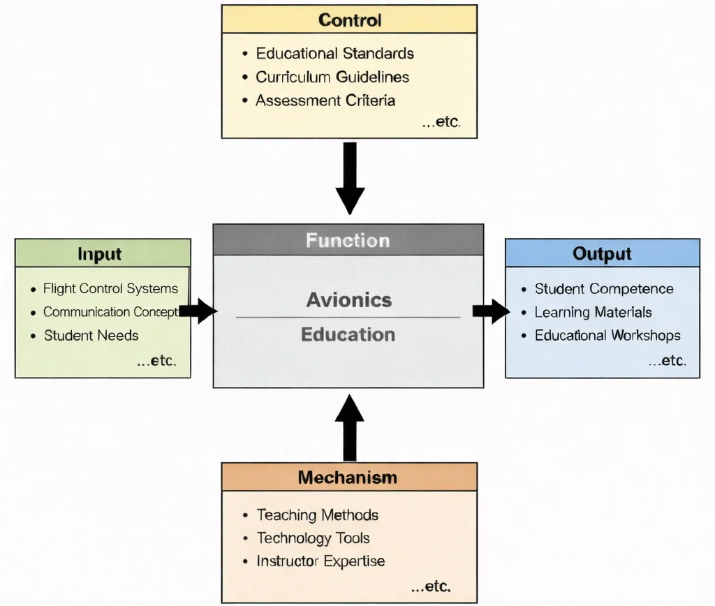
IDEF0 functional decomposition of Avionics Education: flight control and RF communication inputs structured by DO-178C/DO-254 regulatory controls, executed via digital hardware-in-the-loop (HIL) simulators, delivering certified systems integration competencies.

Avionics architecture: integrating digital multi-function cockpit displays, triply-redundant flight control processors, radar cross-links, and distributed databuses to orchestrate real-time situational awareness and guidance.
The image shows a high-tech cockpit packed with multi-function displays, instrumentation panels, and control systems, while a jet flies ahead above Earth’s curved horizon. Transparent, hologram-like overlays of sensors, navigation symbols, and system readouts suggest integrated avionics—flight management, communications, radar, inertial/GNSS navigation, autopilot, and health-monitoring systems working together in real time. Overall, it portrays avionics as the information and decision layer of aerospace engineering, turning sensor data into situational awareness, precise guidance, and safer, more efficient operations.
Sensing, Computation, and Decision Systems
Aerospace & Aeronautical – Overview
Frames how information flows through high-level aerospace architectures to link vehicle operations with real-time navigation and air traffic control.
Avionics (Current Module)
Serves as the electronic brain, integrating onboard sensors, processing units, communication protocols, and flight management systems.
Aero Control Systems & Robotics
Translates electronic avionics commands into physical control surface deflection and automated flight stabilization loops.
Flight Mechanics
Relies on real-time IMU, pitot-static, and GNSS avionics telemetry to model vehicle dynamics and evaluate maneuver trajectories.
Celestial Mechanics
Provides ephemeris data and coordinate frames essential for space-based avionics navigation algorithms and orbital determination.
Propulsion Systems
Interfaces with Digital Engine Control units (FADEC) to monitor fuel injection, turbine temperatures, and thrust management.
Aerodynamics
Feeds raw pressure, temperature, and angle-of-attack air data signals directly into central avionics processing computers.
Hypersonics
Requires ultra-low latency avionics hardware and specialized sensors capable of functioning under high shock and plasma blackout conditions.
Structures
Provides physical enclosures, vibration dampening, and mechanical isolation to protect sensitive avionics circuitry from airframe fatigue.
Materials
Supplies semiconductor substrates, radome dielectrics, and electromagnetic shielding materials essential for reliable electronic hardware.
Spacecraft Engineering
Adapts avionics to radiation-hardened, fault-tolerant architectures tailored for long-duration orbital and interplanetary missions.
Satellite Technology
Employs specialized payload avionics for cross-link communications, attitude determination, and ground command processing.
Core Components of Avionics Systems
Navigation Systems
- Global Navigation Satellite Systems (GNSS):
- Includes GPS, Galileo, GLONASS, and BeiDou for global positioning.
- Provides real-time location, altitude, and velocity data.
- Inertial Navigation Systems (INS):
- Uses accelerometers and gyroscopes to calculate position and orientation without external signals.
- Often integrated with GNSS for redundancy and precision.
- Terrain Awareness and Warning Systems (TAWS):
- Alerts pilots to potential collisions with terrain.
- Uses terrain databases and real-time positioning.
- Radio Navigation:
- Systems like VOR (VHF Omnidirectional Range), DME (Distance Measuring Equipment), and ILS (Instrument Landing System) provide short-range navigation aids.
An X-band weather and obstacle avoidance radar installed in an aircraft nose radome operates at carrier frequency \(f = 9.375 \text{ GHz}\) (\(\lambda = 0.032 \text{ m}\)). Calculate the received signal power \(P_r\) reflected from a non-cooperative target at slant range \(R = 60.0 \text{ km}\) (\(60,000 \text{ m}\)) and verify if the signal exceeds the receiver minimum detectable signal (MDS) threshold \(P_{\text{min}} = -112.0 \text{ dBm}\) (\(6.31 \times 10^{-15} \text{ W}\)) given the following empirical parameters:
- Peak pulse transmit power: \(P_t = 8.0 \text{ kW} = 8,000 \text{ W}\)
- Planar phased array antenna gain: \(G = 34.0 \text{ dBi} \Rightarrow 10^{3.4} \approx 2511.89\) (dimensionless power ratio)
- Target radar cross-section: \(\sigma_{\text{RCS}} = 3.50 \text{ m}^2\)
- Total system & two-way atmospheric attenuation losses: \(L_{\text{sys}} = 4.0 \text{ dB} \Rightarrow 10^{0.4} \approx 2.512\)
Sequential Derivation & Calculation:
Step 1: Calculate the numerator terms of the radar range equation \(\mathcal{N} = P_t \cdot G^2 \cdot \lambda^2 \cdot \sigma_{\text{RCS}}\):
$$G^2 = (2511.89)^2 = 6,309,591.4$$ $$\lambda^2 = (0.032 \text{ m})^2 = 0.001024 \text{ m}^2$$ $$\mathcal{N} = 8,000 \times 6,309,591.4 \times 0.001024 \times 3.50 = 1.8086 \times 10^8 \text{ W}\cdot\text{m}^4$$Step 2: Calculate the geometric propagation denominator \(\mathcal{D} = (4\pi)^3 \cdot R^4 \cdot L_{\text{sys}}\):
$$(4\pi)^3 = 1984.40$$ $$R^4 = (60,000 \text{ m})^4 = 1.296 \times 10^{19} \text{ m}^4$$ $$\mathcal{D} = 1984.40 \times (1.296 \times 10^{19}) \times 2.512 = 6.4603 \times 10^{22} \text{ m}^4$$Step 3: Evaluate received power \(P_r = \mathcal{N} / \mathcal{D}\):
$$P_r = \frac{1.8086 \times 10^8}{6.4603 \times 10^{22}} = \mathbf{2.80 \times 10^{-15} \text{ W}}$$Step 4: Convert received power to \(\text{dBm}\) and evaluate link closure:
$$P_r(\text{dBm}) = 10 \log_{10}\left( \frac{2.80 \times 10^{-15} \text{ W}}{1.0 \times 10^{-3} \text{ W}} \right) = 10 \log_{10}(2.80 \times 10^{-12}) = 10 \times (-11.5528) = \mathbf{-115.53 \text{ dBm}}$$Analysis: Because the received power (\(-115.53 \text{ dBm}\)) falls below the receiver threshold of \(-112.0 \text{ dBm}\) by \(3.53 \text{ dB}\), reliable single-pulse detection at \(60.0 \text{ km}\) fails. To close the link without modifying hardware, digital pulse compression (chirping) and coherent Doppler pulse integration across \(N_{\text{pulses}} \ge 4\) must be applied to raise processing gain.
Communication Systems
- Radio Communication: Air-to-ground and air-to-air communication via VHF, HF, and UHF bands for voice and data transmissions.
- Satellite Communication (SATCOM): Provides global connectivity for long-haul flights and polar routes, supporting weather radar uplinks and air traffic management.
- Automatic Dependent Surveillance-Broadcast (ADS-B): Transmits GPS-derived position, altitude, and velocity at 1090 MHz to air traffic control and nearby aircraft.
Flight Control Systems (FCS)
- Autopilot Systems: Automates altitude hold, route following, and Category III precision approach procedures.
- Fly-by-Wire (FBW): Replaces mechanical linkages with digital flight computers and electro-hydraulic or electromechanical actuators.
- Flight Management Systems (FMS): Central computer optimizing horizontal and vertical navigation profiles, performance limits, and fuel burn.
- Artificial Intelligence in Flight Control: Predictive models mitigating stall, managing asymmetric engine failure, and reallocating control authority under surface damage.
Monitoring and Diagnostic Systems
- Electronic Flight Instrument System (EFIS): Primary Flight Displays (PFD) and Navigation Displays (ND) replacing mechanical gyros.
- Engine Monitoring Systems: Full Authority Digital Engine Controls (FADEC) tracking turbine temperatures and vibration signatures.
- Health and Usage Monitoring Systems (HUMS): Continuous vibration diagnostics for structural integrity and drivetrain health.
Mission-Specific Systems
- Military Avionics: Includes active electronically scanned array (AESA) radar, electronic countermeasures (ECM), and electro-optical targeting pods.
- Spacecraft Avionics: Controls attitude determination and control systems (ADCS), deep-space transponders, and radiation-hardened command buses.
Contemporary AI-Era Computational Paradigms in Avionics
An avionics AHRS processor receives angular velocity measurements from a tri-axial MEMS rate gyro. The true angular rate vector is \(\boldsymbol{\omega} = [0.120, -0.045, 0.350]^T \text{ rad/s}\). The estimated sensor bias vector is \(\hat{\mathbf{b}}_g = [0.005, -0.002, 0.010]^T \text{ rad/s}\). During an inertial update step with time step \(\Delta t = 0.005 \text{ s}\) (\(200 \text{ Hz}\)):
Step 1: Compute the unbiased rate estimate \(\hat{\boldsymbol{\omega}} = \boldsymbol{\omega} - \hat{\mathbf{b}}_g\):
$$\hat{\boldsymbol{\omega}} = [0.120 - 0.005, -0.045 - (-0.002), 0.350 - 0.010]^T = [0.115, -0.043, 0.340]^T \text{ rad/s}$$Step 2: Calculate incremental angular rotation vector \(\Delta \boldsymbol{\theta} = \hat{\boldsymbol{\omega}} \Delta t\):
$$\Delta \boldsymbol{\theta} = [0.115 \times 0.005, -0.043 \times 0.005, 0.340 \times 0.005]^T = [\mathbf{5.75 \times 10^{-4}}, \mathbf{-2.15 \times 10^{-4}}, \mathbf{1.70 \times 10^{-3}}]^T \text{ rad}$$Step 3: Evaluate quaternion rotation update magnitude \(\|\Delta \boldsymbol{\theta}\|\):
$$\|\Delta \boldsymbol{\theta}\| = \sqrt{(5.75 \times 10^{-4})^2 + (-2.15 \times 10^{-4})^2 + (1.70 \times 10^{-3})^2} = \sqrt{3.306 \times 10^{-7} + 4.623 \times 10^{-8} + 2.890 \times 10^{-6}} = \mathbf{1.79 \times 10^{-3} \text{ rad}}$$Advancements in Avionics
Artificial Intelligence (AI) in Avionics
- Automated Flight Operations: AI-powered autopilots capable of handling complex scenarios, including emergency landings and autonomous terrain avoidance.
- Fault Detection and Management: Machine learning models analyze sensor data to predict component failures and recommend corrective actions before unscheduled ground stops.
- Natural Language Processing (NLP): Enables voice-command-based cockpit interactions, reducing pilot workload during high-tempo instrument approaches.
- Computer Vision: Enhances obstacle detection and collision avoidance using real-time infrared and optical video streams for automated taxi and landing operations.
Integration of the Internet of Things (IoT)
- Aircraft systems are increasingly connected to share real-time engine and airframe health data with ground maintenance teams via automated cellular and SATCOM downlinks.
- IoT sensor nodes monitor structural vibration, bearing temperatures, and hydraulic pressures to predict component degradation.
Next-Generation Displays
- Heads-Up Displays (HUD): Projects critical flight information, velocity vectors, and flight director cues onto the cockpit windshield, preserving pilot heads-up orientation.
- Augmented Reality (AR) Displays: Overlays synthetic vision terrain databases, virtual runway outlines, and obstacle cues directly over real-world degraded-visibility viewpoints.
Cybersecurity in Avionics
- Airborne security engineering enforces strict compliance with RTCA DO-326A and DO-356A, establishing cryptographic bus isolation, hardware root-of-trust security modules, and automated intrusion detection systems.
Advanced Data Fusion
- Synthesizes multi-spectral data from radar, lidar, electro-optical sensors, GNSS, and INS into a coherent digital situational model.
- Crucial for autonomous unmanned platforms operating within complex, congested civil airspace.
Engineering Trade-offs in Avionics Systems
| Avionics Design Trade-off | Primary Operational Benefit | Systemic Penalty / Risk | Quantitative Design Metric |
|---|---|---|---|
| Triple Modular Redundancy (TMR) vs. SWaP-C | Guarantees fail-operational capability; voting circuits isolate a failed channel without manual pilot intervention. | Triples hardware acquisition costs, thermal dissipation, chassis volume, and electrical wiring harness weight. | Catastrophic Failure Probability: \(\le 1.0 \times 10^{-9}\) failures per flight hour (FAR Part 25.1309 Level A). |
| Integrated Modular Avionics (IMA) vs. Federated LRUs | Reduces physical computing boxes and wiring bundles by 40%–50%; simplifies depot line replacement. | Requires strict ARINC 653 space and time partitioning; fault in shared backplane can propagate across multiple software partitions. | Wiring Harness Mass Reduction: Up to \(450 \text{ kg}\) saved on wide-body transport airframes. |
| High-Performance COTS Processors vs. Rad-Hard Silicon | Provides multi-gigahertz compute speeds capable of executing deep neural networks and real-time point-cloud fusion. | Susceptible to Single Event Upsets (SEUs) and latch-up caused by atmospheric neutron strikes and cosmic rays. | Single Event Effect (SEE) Soft Error Rate: \(\text{FIT} \le 100\) (Failures in Time per \(10^9\) device operating hours). |
| RF Transmit Power vs. Receiver Thermal Noise Floor | Higher EIRP closes communication links at long slant ranges through dense precipitation and clouds. | Drains aircraft DC generator reserves; generates high RF thermal signatures and electromagnetic interference (EMI). | Link Margin: \(\ge +6.0 \text{ dB}\) in clear air; \(\ge +12.0 \text{ dB}\) under severe tropical convective precipitation. |
Consider an inner attitude rate stabilization loop executing at bandwidth \(\omega_c = 25.0 \text{ rad/s}\). If data transmission between the IMU and flight computer switches from a low-latency point-to-point bus (\(\tau_1 = 1.5 \text{ ms}\)) to an asynchronous shared bus with routing queue delays (\(\tau_2 = 18.0 \text{ ms}\)), the additional phase lag \(\Delta \phi\) introduced into the open-loop transfer function evaluates to:
$$\Delta \phi = \omega_c \cdot (\tau_2 - \tau_1) = 25.0 \text{ rad/s} \times (0.0180 \text{ s} - 0.0015 \text{ s}) = 25.0 \times 0.0165 \text{ s} = \mathbf{0.4125 \text{ rad}} \quad (\mathbf{23.63^\circ})$$Comparison: A phase erosion of \(23.63^\circ\) can reduce nominal system phase margin below the certified safety limit of \(45^\circ\), triggering pilot-induced oscillations (PIO) or control instability. Deterministic bus scheduling (such as TTEthernet or ARINC 664 Part 7) is mandatory to bound transport delay jitter.
Interactive Tool: Avionics Signal Signal-to-Noise Ratio (SNR) Simulator
RF Link Budget & Signal-to-Noise Ratio Calculator
Interactive runtime environment: https://prep4uni.online/stem/physical-technologies/aerospace-and-aeronautical-engineering/avionics/
Applications of Avionics
1. Commercial Aviation
- Avionics systems form the digital backbone of modern commercial aircraft, integrating flight control, navigation, communication, and monitoring into a seamless interface.
- Enhanced safety features such as TCAS (Traffic Collision Avoidance Systems), weather radar, and autopilot systems contribute to significantly reduced accident rates.
- Fuel efficiency is improved through real-time data analytics and flight path optimization, allowing pilots and airlines to make data-driven decisions.
- Cabin avionics improve passenger comfort through in-flight entertainment systems, connectivity, and environmental controls.
- Predictive maintenance and health monitoring systems minimize downtime and streamline operations across global fleets.
2. Military and Defense
- Modern avionics support network-centric warfare, integrating communication, reconnaissance, and targeting into unified platforms.
- Fighter jets employ fly-by-wire systems and Heads-Up Displays (HUDs) that enhance pilot awareness and agility during combat.
- UAVs and autonomous drones rely heavily on robust avionics for navigation, threat detection, and engagement decisions.
- Stealth aircraft use avionics to coordinate sensor fusion, radar evasion, and counter-electronic warfare strategies.
- Encrypted data links and battlefield coordination systems ensure real-time decision-making and mission success.
3. Space Exploration
- Avionics systems in spacecraft handle guidance, telemetry, system diagnostics, and deep-space communication.
- Autonomous systems guide orbital adjustments, reentry trajectories, and landing procedures, especially in missions involving distant celestial bodies.
- Avionics support satellite constellations and inter-satellite communication, crucial for Earth observation and interplanetary exploration.
- They are also essential in ensuring astronaut safety through life-support monitoring, emergency protocols, and robotic interfaces aboard spacecraft.
- Advanced systems are used in missions such as NASA's Perseverance Rover and the ESA Orion Service Module.
4. Urban Air Mobility (UAM)
- eVTOL aircraft use advanced avionics to ensure vertical lift, autonomous flight, and integration with urban air traffic management systems.
- Collision avoidance, route optimization, and passenger safety depend on high-integrity sensors and real-time decision algorithms.
- Communication with urban mobility control centers, vehicle-to-vehicle coordination, and power system monitoring are central to UAM avionics development.
- Regulatory bodies work closely with manufacturers to ensure airworthiness and safety compliance of these emerging transport platforms.
5. General Aviation
- Small aircraft now benefit from the “glass cockpit” revolution, replacing analog gauges with intuitive digital interfaces.
- Modern avionics packages offer features like terrain awareness, synthetic vision, and real-time weather overlays, even for hobbyist pilots.
- Affordable autopilot systems and GPS navigation boost safety and convenience for private aircraft owners.
- Advancements in electronic flight bags (EFBs) and mobile avionics applications enhance flight planning and in-flight updates.
6. Drone Technology
- Drones rely on miniaturized avionics for altitude control, GPS-based navigation, flight stabilization, and camera gimbal management.
- Obstacle avoidance systems use radar, lidar, and computer vision for safe autonomous operations in crowded environments.
- Applications range from precision agriculture and package delivery to wildlife monitoring and tactical surveillance.
- Advances in real-time kinematic positioning and 5G connectivity are pushing the boundaries of drone capabilities.
- Leading platforms are being integrated into emergency response frameworks for disaster relief and medical supply drops.
Challenges in Avionics Development
1. Integration Complexity
2. Regulatory Compliance
3. Cybersecurity Threats
4. Cost and Weight Constraints
5. AI Validation and Trust
Future Trends in Avionics
1. Fully Autonomous Aircraft
- The advancement of artificial intelligence, machine learning, and high-fidelity sensor fusion is enabling aircraft to fly, navigate, and land without human intervention.
- Autonomous avionics systems will use deep neural networks for real-time decision-making, object detection, and dynamic flight path optimization.
- These technologies are being tested in cargo drones, urban air mobility (UAM) vehicles, and are expected to scale to commercial passenger aircraft by the 2030s.
- Regulatory agencies are working toward the certification of autonomous flight systems under stringent safety protocols.
2. Green Avionics
- Avionics systems are increasingly being designed for integration with hybrid-electric and fully electric propulsion systems to reduce greenhouse gas emissions.
- Innovations include energy-optimized flight control algorithms, power management systems, and avionics compatible with distributed propulsion architectures.
- Electric Vertical Takeoff and Landing (eVTOL) aircraft and short-range commuter planes benefit most from lightweight, efficient avionics systems.
- Flight data optimization and trajectory automation contribute to lower fuel consumption and noise pollution.
3. Enhanced Human-Machine Interaction (HMI)
- Future cockpits are evolving toward natural interaction paradigms such as augmented reality (AR), voice recognition, and touchless gesture-based controls.
- These interfaces reduce pilot workload and cognitive stress by simplifying access to critical information through head-up displays (HUDs) and smart helmets.
- Adaptive interfaces powered by AI can tailor flight displays and system behavior to the pilot’s level of experience or current operational context.
4. Space Avionics Innovations
- The future of space exploration demands avionics systems capable of withstanding radiation, extreme temperatures, and deep-space latency.
- Reusable launch vehicles, lunar landers, and Mars missions require fault-tolerant onboard computing, autonomous navigation, and intelligent health monitoring systems.
- Avionics systems are also evolving to support swarm satellite architectures and in-orbit servicing through AI-driven collaboration and coordination.
5. Quantum Avionics
- Quantum technologies are emerging as a breakthrough for ultra-precise positioning, navigation, and timing (PNT) systems that do not rely on GPS.
- Quantum inertial navigation systems (QINS) can maintain location accuracy even in GPS-denied environments such as underground, underwater, or during signal jamming.
- Quantum key distribution (QKD) is expected to revolutionize secure communications in defense aviation by offering unbreakable encryption.
Why Study Avionics
Integrated Electronic Systems
Navigation and Guidance Technologies
Flight Control and Automation
Software and Hardware Integration
Future Technologies and Innovations
Avionics Conclusion
Frequently Asked Questions on Avionics
These FAQs help you see how avionics turns an airframe into a safe, intelligent flying machine, from basic electronics to advanced flight management.
1. What does “avionics” actually cover in a modern aircraft?
Avionics covers almost all of the electronic systems that support flight: communication radios, navigation and GPS equipment, flight control computers, cockpit displays, flight management systems, surveillance and collision-avoidance equipment, and health-monitoring sensors. Together, these systems help pilots fly safely, efficiently and in compliance with air traffic regulations.
2. How have modern avionics systems improved flight safety?
Modern avionics improve safety by giving pilots more accurate, timely information and by automating routine or high-workload tasks. Enhanced navigation and terrain-awareness systems reduce the risk of controlled flight into terrain, while traffic-alert and collision-avoidance systems warn of nearby aircraft. Flight control computers and autopilots help maintain stable flight, especially in poor weather, reducing pilot workload and the chance of human error.
3. What is the role of communication systems within avionics?
Communication systems provide reliable voice and data links between the aircraft and the outside world. Radios connect pilots with air traffic control and other aircraft, while data links support services such as weather updates, flight plan changes and airline operations messages. Clear, dependable communication is essential for safe coordination in congested airspace and during abnormal or emergency situations.
4. How do navigation and flight management systems work together?
Navigation systems determine the aircraft’s position and movement using sensors such as GPS, inertial reference systems and radio beacons. The flight management system (FMS) uses this information, together with the planned route and performance data, to compute an optimal trajectory. It then guides the autopilot and displays to follow that path, helping crews fly fuel-efficient routes and meet time and altitude constraints set by air traffic control.
5. What is Integrated Modular Avionics (IMA), and why does it matter?
Integrated Modular Avionics (IMA) is an architecture where many avionics functions share common computing hardware and software platforms instead of using separate “black boxes” for each function. This reduces wiring, weight and maintenance complexity, and makes it easier to add or update functions through software. However, it also demands rigorous partitioning and certification so that critical and non-critical functions can safely coexist on the same hardware.
6. How do avionics systems enhance fuel efficiency and operational performance?
Avionics enhance fuel efficiency by supporting precise navigation, continuous descent operations and optimal speed and altitude profiles. Performance-monitoring systems give real-time feedback on engine and airframe efficiency, while the FMS can suggest route or level changes that save fuel. Over a fleet’s lifetime, these small optimisations accumulate into significant cost savings and reduced environmental impact.
7. Why is cybersecurity becoming a major topic in avionics?
As aircraft rely more on digital communication and networked systems, they become potential targets for cyber threats. Cybersecurity aims to protect avionics from unauthorised access, malicious software and data manipulation that could affect safety or operational continuity. Secure architectures, encryption, strict access control and continuous monitoring are increasingly built into modern avionics to preserve both flight safety and data integrity.
8. What future trends are shaping the next generation of avionics?
Future avionics trends include more powerful integrated computing platforms, greater use of artificial intelligence for decision support, enhanced connectivity with ground systems, and interfaces designed for single-pilot or highly automated operations. There is also a strong focus on open architectures and modular software so that systems can be updated more easily over an aircraft’s life. These developments aim to improve safety, efficiency and flexibility as air traffic and environmental constraints grow.
Avionics: Practice & Assessment Module
Section 1: Interactive Review Questions
1. What does the term “avionics” encompass in modern aircraft?
2. How have advancements in avionics improved flight safety?
3. What role do communication systems play within avionics?
4. Can you name a common navigation system used in modern aircraft, and explain its purpose?
5. What is the significance of flight control and autopilot systems in avionics?
6. How do avionics systems contribute to fuel efficiency and environmental performance?
7. What is the role of Integrated Modular Avionics (IMA) in modern aircraft?
8. How do avionics systems enhance situational awareness for pilots?
9. What recent advancements have been made in avionics for highly automated and autonomous flying?
10. Why is cybersecurity an increasingly important consideration in avionics design?
Section 2: Interactive Thought-Provoking Questions
1. How might the integration of artificial intelligence transform future avionics systems?
2. In what ways can advancements in avionics contribute to the development of urban air mobility solutions?
3. How do avionics systems manage the increasing complexity of modern aircraft operations?
4. What are the challenges associated with integrating new avionics technologies into existing aircraft fleets?
5. How do avionics systems contribute to environmental sustainability in aviation?
6. What role do avionics play in enhancing passenger experience during flights?
7. How do avionics systems ensure redundancy and reliability in critical flight operations?
8. In what ways are avionics systems evolving to address emerging cybersecurity threats?
9. How do regulatory standards influence the development and implementation of avionics systems?
10. What potential does quantum computing hold for the future of avionics systems?
Section 3: Numerical Problems & Step-by-Step Solutions
1. Radar Pulse Time Delay and Slant Range Calculation
Problem: An airborne weather radar emits a pulse toward a storm front and detects the echo returning after a round-trip time delay \(\Delta t = 800 \text{ \mu s}\). Calculate the slant range \(R\) to the storm in kilometers (speed of light \(c = 3.0 \times 10^8 \text{ m/s}\)).
Answer:
Step 1: Convert time delay to seconds:
\(\Delta t = 800 \text{ \mu s} = 800 \times 10^{-6} \text{ s} = 0.00080 \text{ s}\)
Step 2: Apply the radar range formula:
\(R = \frac{c \cdot \Delta t}{2}\)
Step 3: Substitute values and calculate distance in meters:
\(R = \frac{3.0 \times 10^8 \text{ m/s} \times 0.00080 \text{ s}}{2} = \frac{240,000 \text{ m}}{2} = 120,000 \text{ m}\)
Step 4: Convert to kilometers:
\(R = \frac{120,000 \text{ m}}{1,000} = \mathbf{120.0 \text{ km}}\)
The slant range to the storm front is 120.0 km.
2. Free-Space Path Loss (FSPL) for VHF Communication
Problem: A VHF radio comm link between an aircraft and ground tower operates at frequency \(f = 120.0 \text{ MHz}\) across distance \(d = 100.0 \text{ km}\). Calculate the Free-Space Path Loss (\(\text{FSPL}\)) in decibels using the standard formula: \(\text{FSPL(dB)} = 20 \log_{10}(d) + 20 \log_{10}(f) + 32.44\) (where \(d\) is in \(\text{km}\) and \(f\) is in \(\text{MHz}\)).
Answer:
Step 1: Calculate distance logarithmic component:
\(20 \log_{10}(100.0) = 20 \times 2.0 = 40.00 \text{ dB}\)
Step 2: Calculate frequency logarithmic component:
\(20 \log_{10}(120.0) = 20 \times 2.07918 = 41.58 \text{ dB}\)
Step 3: Sum the individual components:
\(\text{FSPL} = 40.00 + 41.58 + 32.44 = \mathbf{114.02 \text{ dB}}\)
The total Free-Space Path Loss is 114.02 dB.
3. Transmitter Power dBm Conversion & Link Margin
Problem: An ADS-B avionics transponder outputs \(P = 25.0 \text{ W}\) of RF transmit power. Convert this power level to \(\text{dBm}\). If the total propagation path loss is \(130.0 \text{ dB}\) and receiver sensitivity is \(-95.0 \text{ dBm}\), determine if the link closes.
Answer:
Step 1: Convert transmit power from Watts to milliwatts:
\(P = 25.0 \text{ W} = 25,000 \text{ mW}\)
Step 2: Calculate power in \(\text{dBm}\):
\(P(\text{dBm}) = 10 \log_{10}(25,000) = 10 \times 4.39794 = \mathbf{43.98 \text{ dBm}}\)
Step 3: Calculate received signal power \(P_{\text{rx}}\):
\(P_{\text{rx}} = 43.98 \text{ dBm} - 130.0 \text{ dB} = \mathbf{-86.02 \text{ dBm}}\)
Step 4: Check against the receiver sensitivity threshold (\(-95.0 \text{ dBm}\)):
\(\text{Link Margin} = P_{\text{rx}} - P_{\text{sens}} = -86.02 \text{ dBm} - (-95.0 \text{ dBm}) = \mathbf{+8.98 \text{ dB}}\)
The link closes successfully with an operating reserve margin of +8.98 dB above receiver sensitivity.
4. ARINC 429 Bus Data Rate and Word Transmission Time
Problem: A high-speed ARINC 429 digital data bus operates at a transmission bit rate of \(100 \text{ kbps}\) (\(100,000 \text{ bps}\)). Each ARINC 429 data word contains exactly \(32 \text{ bits}\). Calculate the transmission duration of a single 32-bit word in microseconds and the maximum word throughput per second.
Answer:
Step 1: Calculate word transmission duration:
\(t_{\text{word}} = \frac{32 \text{ bits}}{100,000 \text{ bits/s}} = 0.00032 \text{ s}\)
Step 2: Convert duration to microseconds:
\(t_{\text{word}} = 0.00032 \times 10^6 \text{ \mu s} = \mathbf{320.0 \text{ \mu s}}\)
Step 3: Calculate maximum word capacity throughput per second:
\(\text{Throughput} = \frac{100,000 \text{ bits/s}}{32 \text{ bits/word}} = \mathbf{3,125 \text{ words/s}}\)
A single word takes 320.0 \(\mu\text{s}\) to transmit, yielding a maximum throughput of 3,125 words per second.
5. Inertial Measurement Unit (IMU) Position Drift Integration
Problem: An unassisted Inertial Navigation System accelerometer has a constant uncalibrated bias error \(a_{\text{bias}} = 0.002 \text{ m/s}^2\). Calculate the resulting accumulated positional drift error \(\Delta x\) after \(t = 1 \text{ hour}\) (\(3600 \text{ s}\)) of unassisted dead-reckoning flight using double integration (\(\Delta x = \frac{1}{2} a_{\text{bias}} t^2\)).
Answer:
Step 1: Square time duration:
\(t^2 = (3600 \text{ s})^2 = 12,960,000 \text{ s}^2\)
Step 2: Apply the double integration formula:
\(\Delta x = \frac{1}{2} \times 0.002 \text{ m/s}^2 \times 12,960,000 \text{ s}^2\)
Step 3: Evaluate spatial displacement:
\(\Delta x = 0.001 \times 12,960,000 = \mathbf{12,960 \text{ m}}\)
Step 4: Convert displacement to kilometers:
\(\Delta x = \frac{12,960 \text{ m}}{1,000} = \mathbf{12.96 \text{ km}}\)
The uncalibrated accelerometer bias accumulates a positional error drift of 12.96 km after one hour.
6. Doppler Shift Frequency Calculation for Airborne Radar
Problem: An aircraft flying at relative closing velocity \(v = 250.0 \text{ m/s}\) toward a radar ground station emits a signal at carrier frequency \(f_0 = 10.0 \text{ GHz}\) (\(10.0 \times 10^9 \text{ Hz}\)). Calculate the resulting two-way Doppler frequency shift \(f_{\text{d}} = \frac{2 v f_0}{c}\) (where \(c = 3.0 \times 10^8 \text{ m/s}\)).
Answer:
Step 1: Calculate the numerator product:
\(\text{Numerator} = 2 \times 250.0 \text{ m/s} \times 10.0 \times 10^9 \text{ Hz} = 5.0 \times 10^{12}\)
Step 2: Divide by the propagation velocity (speed of light):
\(f_{\text{d}} = \frac{5.0 \times 10^{12}}{3.0 \times 10^8} = 16,666.67 \text{ Hz}\)
Step 3: Convert frequency to kilohertz:
\(f_{\text{d}} = \frac{16,666.67 \text{ Hz}}{1,000} = \mathbf{16.67 \text{ kHz}}\)
The measured two-way Doppler shift is 16.67 kHz.
7. Receiver Thermal Noise Floor Power Calculation
Problem: An avionics receiver operating at temperature \(T = 290.0 \text{ K}\) has a channel bandwidth \(B = 10.0 \text{ MHz}\) (\(10^7 \text{ Hz}\)). Calculate the thermal noise floor power \(N\) in Watts using \(N = k \cdot T \cdot B\) (where Boltzmann constant \(k = 1.38 \times 10^{-23} \text{ J/K}\)) and convert to \(\text{dBm}\).
Answer:
Step 1: Calculate noise power in Watts:
\(N = 1.38 \times 10^{-23} \text{ J/K} \times 290.0 \text{ K} \times 10^7 \text{ Hz} = \mathbf{4.002 \times 10^{-14} \text{ W}}\)
Step 2: Convert power to milliwatts:
\(N(\text{mW}) = 4.002 \times 10^{-14} \times 1,000 = \mathbf{4.002 \times 10^{-11} \text{ mW}}\)
Step 3: Convert to logarithmic power ratio (\(\text{dBm}\)):
\(N(\text{dBm}) = 10 \log_{10}(4.002 \times 10^{-11}) = 10 \times (-10.3977) = \mathbf{-103.98 \text{ dBm}}\)
The receiver thermal noise floor power is -103.98 dBm.
8. Software Reliability Availability Rate Evaluation
Problem: A DO-178C Level A certified primary flight computer has an operational Mean Time Between Failures (\(\text{MTBF}\)) of \(50,000 \text{ hours}\) and a line Mean Time To Restore (\(\text{MTTR}\)) of \(0.5 \text{ hours}\). Calculate the steady-state system availability \(A = \frac{\text{MTBF}}{\text{MTBF} + \text{MTTR}}\) and express as a percentage.
Answer:
Step 1: Calculate total cycle operational time:
\(\text{MTBF} + \text{MTTR} = 50,000 + 0.5 = 50,000.5 \text{ hours}\)
Step 2: Compute availability ratio:
\(A = \frac{50,000}{50,000.5} = 0.9999900001\)
Step 3: Convert ratio to percentage:
\(A(\%) = 0.9999900001 \times 100\% = \mathbf{99.9990\%}\)
The certified flight computer system availability is 99.9990% (five-nines availability).