
Additive Manufacturing (3D Printing) Education is where a workshop mindset meets systems thinking. Using the diagram below as a guide, students learn to take raw information about materials and processes and convert it into planned, controllable production. They practice working within non-negotiable constraints—quality requirements, safety rules, and industry procedures—so their designs and decisions survive contact with the factory floor. With tools such as CNC equipment and automation platforms, they move from theory to execution: selecting parameters, validating processes, and improving throughput without sacrificing reliability. What emerges is not only the ability to manufacture, but the ability to engineer manufacturing—planning work, reducing waste, and steadily lifting performance in real, operating systems.
- Melt-Pool Physics & Volumetric Energy Density (VED): Formulate the thermodynamic relationship \(E_v = \frac{P}{v \cdot h \cdot t}\) governing laser-powder interactions, keyhole threshold instabilities, and balling phenomena in Powder Bed Fusion.
- Design for Additive Manufacturing (DfAM): Apply topology optimization, conformal cooling channel fluidics, self-supporting overhang constraints (\(\theta \ge 45^\circ\)), and gyroid triply periodic minimal surface (TPMS) lattice design.
- Anisotropy, Metallurgy & Post-Processing: Evaluate columnar-to-equiaxed grain transitions, z-axis interlayer bonding degradation, Hot Isostatic Pressing (HIP) densification, and residual stress mitigation.
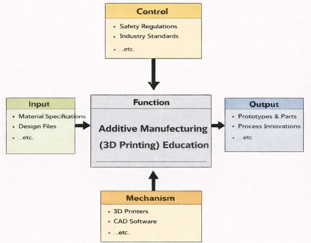
This IDEF0-style diagram frames Additive Manufacturing (3D Printing) Education as a structured learning system. On the left, Input highlights what learners start with (material specifications, design files, etc.). Above, Control sets the boundaries for responsible practice (safety regulations, industry standards, etc.). At the bottom, Mechanism names the enabling resources (3D printers, CAD software, etc.). On the right, Output captures what the learning process produces (prototypes & parts, process innovations, etc.). Together, the boxes show how practical tools and real-world rules guide students from digital designs to physical results.
Additive Manufacturing (3D Printing) has revolutionized the way we conceive, prototype, and produce objects, breaking away from traditional subtractive processes by building components layer by layer. This innovative approach aligns closely with broader developments in Industrial and Manufacturing Technologies, offering unprecedented design freedom and rapid iteration cycles. It plays a critical role in accelerating product development and creating complex geometries that were previously difficult or impossible to fabricate.
The synergy between additive processes and Advanced Materials and Manufacturing Technologies allows engineers to explore high-performance composites, metals, and polymers tailored for aerospace, biomedical, and automotive sectors. This capability is further amplified by the integration of Computer-Integrated Manufacturing (CIM) systems and Digital Twin Technology, enabling digital workflows that simulate, monitor, and optimize the manufacturing process in real time.
As sustainability becomes central to industrial strategy, additive techniques contribute to Energy and Resource Efficiency in Manufacturing. By minimizing waste, reducing the need for tooling, and enabling local production, 3D printing aligns with the goals of Sustainable Manufacturing. Additionally, its flexibility supports leaner operations, complementing methods taught under Lean Manufacturing.
Interactive System Dynamics: Additive Manufacturing Build Kinetics & Thermal Energy Simulator
Simulate build time, Volumetric Energy Density (VED), and layer deposition rates. Adjust laser power, scan speed, hatch spacing, and layer thickness to evaluate process parameter windows and avoid lack-of-fusion or keyholing defects in real time.
Process Parameters
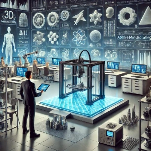
Layered Fabrication: Flexibility, Customisation, and Digital Production
Additive Manufacturing (3D Printing) has evolved from an experimental prototyping method into an industrial production system. By depositing material layer by layer directly from CAD geometries, this technology unlocks lightweight lattice structures, internal fluid passages, and rapid design customization impossible under traditional subtractive paradigms.
Industrial & Manufacturing Technologies – Overview
Positions additive manufacturing within the broader landscape of modern production technologies, linking shop-floor execution to overarching factory systems.
Advanced Materials
Develops high-performance alloys, photopolymer resins, and composite feedstocks specifically tailored for layer-by-layer fusion.
Process Design
Optimises printing parameters, slicing toolpaths, thermal gradients, and laser scan vectors to maximize build speed and mechanical density.
Quality Control
Ensures dimensional accuracy, surface roughness compliance, and internal microvoid elimination using non-destructive testing and in-situ melt-pool monitoring.
Smart Manufacturing
Integrates 3D printers into IIoT networks for automated job-shop scheduling, remote machine monitoring, and continuous quality data logging.
Digital Twin
Simulates thermal stresses, part warping, and powder bed recoating in a virtual model before physically firing the laser.
Automation
Automates build plate swapping, depowdering operations, and robotic post-processing to scale 3D printing into 24/7 serial production.
CIM
Connects digital CAD files directly to MES and ERP management software, removing manual file preparation steps across facilities.
Supply Chain
Enables decentralized, on-demand spare part production, eliminating physical warehouse stocks and long-distance shipping overheads.
Lean Manufacturing
Reduces material waste and inventory holding costs by executing near-net-shape builds with zero hard tooling setup requirements.
Sustainable Manufacturing
Minimizes raw material scrap and supports circular bio-polymer or recycled feedstock integration in production loops.
Energy Efficiency
Optimizes specific electrical energy consumption per kilogram of fused material during extended build cycles.
Human Factors
Designs safe depowdering environments, intuitive slicing user interfaces, and ergonomic post-processing workstations.
Core Concepts of Additive Manufacturing
The Additive Process Lifecycle
- Parametric CAD & Mesh Tesselation: Components originate in solid CAD software and are discretized into triangulated surface meshes (STL, 3MF). Slicing engines interpolate horizontal layer boundaries and generate vectorized toolpaths.
- Laser/Nozzle Scan Path Kinematics: Galvo mirrors or gantry drives steer the heat source along contour and hatch vectors. Slicing algorithms alternate raster angles (e.g., \(0^\circ/90^\circ\) or \(67^\circ\) rotation per layer) to disrupt directional grain anisotropy.
- Melt-Pool Solidification: Rapid local heating causes localized phase change followed by steep cooling rates (\(10^3 - 10^6\text{ K/s}\)), giving rise to fine cellular-dendritic microstructures and residual thermal stress fields.
- Metallurgical & Mechanical Post-Processing: Raw builds undergo electrical discharge machining (EDM) plate separation, Hot Isostatic Pressing (HIP) at high argon pressures (\(100 - 150\text{ MPa}\)) to close gas porosity, and CNC finishing on mating faces.
Primary Additive Processing Technologies
- Laser Powder Bed Fusion (LPBF / DMLS / SLM): Ytterbium fiber lasers melt fine spherical metal powders (\(15 - 53\text{ µm}\)) under an argon or nitrogen inert environment to prevent oxidation.
- Electron Beam Powder Bed Fusion (E-PBF / EBM): High-energy electron beams in a high vacuum (\(10^{-4}\text{ mbar}\)) maintain elevated bed temperatures (\(650 - 1,000^\circ\text{C}\)), producing low-residual-stress parts in titanium aluminides and superalloys.
- Selective Laser Sintering (SLS): \(\text{CO}_2\) lasers sinter engineering polymers (Nylon PA11/PA12), with un-sintered surrounding powder providing natural self-support.
- Stereolithography (SLA) & Digital Light Processing (DLP): Photopolymer resins undergo free-radical or cationic cross-linking polymerization under UV laser or projector exposure.
- Fused Deposition Modeling (FDM / FFF): Continuous thermoplastic filaments (PEEK, ULTEM, PLA) melt through a heated liquefier nozzle, bonding via thermal polymer diffusion.
- Binder Jetting: Liquid binder drops selectively bond powdered metals, sand, or ceramics; green parts undergo debinding and high-temperature furnace sintering to achieve solid density.
Problem Formulation: Volumetric Energy Density, Solidification Cooling Rates & Thermal Residual Stresses
An aerospace materials engineer is qualifying a Laser Powder Bed Fusion (LPBF) process for a critical Ti6Al4V structural bracket. The continuous-wave ytterbium fiber laser delivers power \(P = 280.0\text{ W}\) with a focused beam spot diameter \(d = 80.0\text{ µm}\). The laser scans across the powder bed at a velocity \(v = 950.0\text{ mm/s}\) with a hatch spacing \(h = 100.0\text{ µm}\) and a powder layer thickness \(t = 30.0\text{ µm}\). Calculate the Volumetric Energy Density (\(E_v\)), the 1D Rosenthal cooling rate estimate (\(\frac{\partial T}{\partial t}\)) at the liquidus boundary (\(T_m = 1,660^\circ\text{C}\), preheat \(T_0 = 100^\circ\text{C}\)), and the resulting thermal residual stress (\(\sigma_{\text{th}}\)) assuming an unconstrained thermal expansion mismatch model.
- Thermal conductivity: \(k = 7.20\text{ W/m}\cdot\text{K}\); Specific heat capacity: \(c_p = 560.0\text{ J/kg}\cdot\text{K}\)
- Alloy solid density: \(\rho = 4,430.0\text{ kg/m}^3\); Young's modulus: \(E = 114.0\text{ GPa}\)
- Coefficient of thermal expansion: \(\alpha = 8.60 \times 10^{-6}\text{ K}^{-1}\); Poisson's ratio: \(\nu = 0.342\)
- Melting liquidus temperature: \(T_m = 1,660.0^\circ\text{C}\); Build plate preheat: \(T_0 = 100.0^\circ\text{C}\)
Step 1: Volumetric Energy Density (\(E_v\)) Formulation
Convert units to millimeters: \(P = 280.0\text{ W}\), \(v = 950.0\text{ mm/s}\), \(h = 0.100\text{ mm}\), \(t = 0.030\text{ mm}\):
$$E_v = \frac{P}{v \cdot h \cdot t} = \frac{280.0\text{ J/s}}{950.0\text{ mm/s} \times 0.100\text{ mm} \times 0.030\text{ mm}}$$ $$E_v = \frac{280.0}{2.850} = \mathbf{98.246\text{ J/mm}^3}\quad (9.825 \times 10^{10}\text{ J/m}^3)$$Step 2: Linear Energy Density (\(E_l\)) and Areal Energy Density (\(E_a\))
$$E_l = \frac{P}{v} = \frac{280.0\text{ W}}{0.950\text{ m/s}} = \mathbf{294.74\text{ J/m}}\quad (0.2947\text{ J/mm})$$ $$E_a = \frac{P}{v \cdot h} = \frac{280.0}{950.0 \times 0.100} = \mathbf{2.947\text{ J/mm}^2}$$Step 3: Solidification Cooling Rate via 1D Rosenthal Moving Heat Source
Calculate thermal diffusivity \(\alpha_D = \frac{k}{\rho \cdot c_p}\):
$$\alpha_D = \frac{7.20\text{ W/m}\cdot\text{K}}{4,430.0\text{ kg/m}^3 \times 560.0\text{ J/kg}\cdot\text{K}} = \frac{7.20}{2,480,800} = 2.9023 \times 10^{-6}\text{ m}^2\text{/s}$$Apply the centerline cooling rate formulation at temperature \(T = T_m = 1,660.0^\circ\text{C}\):
$$\frac{\partial T}{\partial t} = -2\pi \cdot k \cdot \rho \cdot c_p \cdot \left(\frac{v}{P}\right) \cdot (T_m - T_0)^2$$ $$\frac{\partial T}{\partial t} = -2\pi \times (7.20) \times (2,480,800) \times \left(\frac{0.950}{280.0}\right) \times (1,660.0 - 100.0)^2$$ $$\frac{\partial T}{\partial t} = -1.1223 \times 10^8 \times (0.0033928) \times (1,560.0)^2$$ $$\frac{\partial T}{\partial t} = -380,774 \times 2,433,600 = \mathbf{-9.266 \times 10^5\text{ K/s}}\quad (\approx -10^6\text{ K/s})$$Step 4: Theoretical Unconstrained Thermal Residual Stress (\(\sigma_{\text{th}}\))
Estimate the plane-strain thermal stress across temperature gradient \(\Delta T = T_m - T_0 = 1,560.0\text{ K}\):
$$\sigma_{\text{th}} = \frac{E \cdot \alpha \cdot \Delta T}{1 - \nu}$$ $$\sigma_{\text{th}} = \frac{(114.0 \times 10^9\text{ Pa}) \times (8.60 \times 10^{-6}\text{ K}^{-1}) \times 1,560.0\text{ K}}{1 - 0.342} = \frac{1,529,424,000}{0.658} = \mathbf{2.324\text{ GPa}}$$Systems Engineering Trade-Off Matrix: Industrial Additive Technologies
Selecting additive manufacturing platforms requires balancing volumetric deposition rate, mechanical isotropy, feedstock costs, dimensional tolerances, and post-processing complexity.
| Additive Technology | Deposition & Energy Source | Build Rate & Density | Mechanical Isotropy & Strength | Tolerances & Surface (\(Ra\)) | Post-Processing Requirements |
|---|---|---|---|---|---|
| LPBF / DMLS (Metal) | Fiber laser (\(200 - 1,000\text{ W}\)) bed melting | Slow (\(10 - 40\text{ cm}^3\text{/h}\)); density \(\gt 99.8\%\) | High static strength; brittle \(\alpha'\) martensite | \(\pm 0.1\text{ mm}\); \(Ra = 8 - 15\text{ µm}\) | EDM cutoff, stress relief, support removal, HIP |
| Electron Beam (E-PBF) | High-vacuum electron beam (\(3 - 6\text{ kW}\)) | High (\(50 - 100\text{ cm}^3\text{/h}\)); dense | Superior fracture toughness; low residual stress | \(\pm 0.3\text{ mm}\); rough (\(Ra = 20 - 35\text{ µm}\)) | Powder recovery system (PRS), CNC surface milling |
| Selective Laser Sintering (SLS) | \(\text{CO}_2\) laser polymer powder bed fusion | Moderate (\(30 - 80\text{ cm}^3\text{/h}\)); dense | Near-isotropic (\(z\)-strength \(\approx 90\%\) of \(xy\)) | \(\pm 0.2\text{ mm}\); granular (\(Ra = 6 - 12\text{ µm}\)) | No supports; media bead blasting, vapor smoothing |
| Stereolithography (SLA) | UV galvo laser photopolymerization | Slow-to-moderate; 100% solid density | Brittle; photopolymer degrades under outdoor UV | Superior (\(\pm 0.05\text{ mm}\); \(Ra \lt 1.0\text{ µm}\)) | IPA solvent wash, UV curing oven, support clipping |
| Fused Filament (FDM / FFF) | Heated liquefier nozzle thermoplastic extrusion | Variable (\(15 - 50\text{ cm}^3\text{/h}\)); infill voids | Highly anisotropic (\(z\)-strength \(40 - 60\%\) of \(xy\)) | Stair-stepping (\(Ra = 15 - 30\text{ µm}\)) | Breakaway/soluble support removal, light sanding |
Applications of Additive Manufacturing
- Aerospace Propulsion & Structural Lightweighting: Single-piece rocket engine combustion chambers and jet turbine fuel nozzles consolidate up to 85 discrete parts into a single monolithic component with conformal internal cooling channels.
- Patient-Specific Orthopedic & Dental Biomechanics: Titanium hip stems and porous cranial implants match patient-specific CT scan data, using open-cell lattice geometries that promote natural bone ingrowth (osseointegration).
- Automotive Tooling & Rapid Jigs: Lightweight carbon-fiber-reinforced composite assembly fixtures and rapid robot end-effectors reduce tooling lead times from months to days.
- High-Performance Injection Mold Tooling: Conformal cooling channels inside tool steel mold inserts curve smoothly around mold cavities, cutting plastic cycle cooling times by 30%.
Why Study Additive Manufacturing (3D Printing)
Design for Additive Manufacturing (DfAM)
Students master topology optimization, internal gyroid lattice generation, and part consolidation techniques to exploit additive design freedom.
Advanced Laser-Material Processing Metallurgy
Engineers analyze melt-pool Marangoni flow, thermodynamic energy density thresholds, and post-weld heat treatment routines for high-performance superalloys.
Digital Thread & Industry 4.0 Integration
Coursework covers digital workflows connecting generative design algorithms with in-situ melt-pool pyrometry and cloud-connected MES platforms.
Sustainable & Agile Supply Chain Operations
Students evaluate near-net-shape buy-to-fly material ratios, on-demand distributed spare parts production, and circular metal powder reclamation.
Additive Manufacturing: Conclusion
Additive manufacturing has matured from a rapid prototyping technique into an established industrial production discipline. By enabling digital design execution, topology-optimized lightweighting, and localized supply chain delivery, 3D printing drives sustainable, agile, and customized manufacturing across global sectors.
Frequently Asked Questions
What is the difference between additive and subtractive manufacturing?
Additive manufacturing builds components layer-by-layer directly from CAD data, placing material only where needed. Subtractive manufacturing cuts material away from a solid billet via CNC milling or turning. Additive excels at complex internal voids and low-volume production, while subtractive provides higher volumetric production rates and tighter surface tolerances for simpler shapes.
Why do metal 3D-printed parts exhibit mechanical anisotropy?
During Powder Bed Fusion, directional heat extraction down through the build plate promotes epitaxial grain growth along the vertical build direction (z-axis). Because grain boundaries align vertically and interlayer thermal fusion can contain microscopic lack-of-fusion defects, vertical tensile strength and fatigue life are typically lower than in the horizontal plane.
What is the role of Hot Isostatic Pressing (HIP) in metal additive manufacturing?
Hot Isostatic Pressing subjects printed metal components to elevated temperatures (e.g., 900–1,200°C) and isostatic inert gas pressure (100–150 MPa) inside a pressure vessel. This process plastically collapses internal micro-voids and gas pores through creep, achieving near 100% theoretical density and restoring dynamic fatigue resistance.
End-of-Page Practice & Assessment Modules
Section 1: Interactive Foundational Concepts Review
Question 1: Process Mechanics
Question 2: Slicing Workflow
Question 3: Selective Laser Sintering (SLS) Self-Support
Question 4: Design for Additive Manufacturing (DfAM)
Section 2: Analytical & Scenario-Based Inquiry
Question 1: Anisotropy & Part Orientation Analysis
Question 2: Aerospace Lightweighting Trade-Offs
Question 3: Surface Finish Mitigation via Hybrid Systems
Section 3: Applied Engineering Quantitative Calculations
Problem 1: Total Build Layer Count Calculation
Question: A medical implant designer needs to print a titanium spinal cage with a total height of \(45.0\text{ mm}\) using an SLM system configured with a layer thickness of \(30.0\text{ µm}\). Calculate the total number of layers required.
Solution:
1. Convert total height to micrometers: \(45.0\text{ mm} \times 1,000.0\text{ µm/mm} = 45,000.0\text{ µm}\)
2. Layer count calculation:
$$N_{\text{layers}} = \frac{45,000.0\text{ µm}}{30.0\text{ µm/layer}} = \mathbf{1,500\text{ layers}}$$Problem 2: Build Time Estimation
Question: An FDM printer fabricates an enclosure with a build height of \(80.0\text{ mm}\) at a layer height of \(0.20\text{ mm}\). Each layer requires an average of \(45.0\text{ seconds}\) to deposit, plus \(5.0\text{ seconds}\) for recoating/indexing. Calculate total build time in hours and minutes.
Solution:
1. Total layers: \(\frac{80.0\text{ mm}}{0.20\text{ mm/layer}} = 400\text{ layers}\)
2. Time per layer: \(45.0\text{ s} + 5.0\text{ s} = 50.0\text{ seconds}\)
3. Total build time: \(400 \times 50.0\text{ s} = 20,000.0\text{ seconds}\)
4. Convert to hours: \(\frac{20,000.0}{3,600} = 5.556\text{ hours} = \mathbf{5\text{ hours and } 33\text{ minutes}}\)
Problem 3: Polymer Feedstock Cost Calculation
Question: A CAD model has a net volume of \(120.0\text{ cm}^3\). The part is printed in PLA (\(\rho = 1.24\text{ g/cm}^3\)) using a \(40.0\%\) infill density. PLA filament costs \(\$30.00\text{/kg}\). Calculate the net raw material cost.
Solution:
1. Effective polymer volume: \(120.0\text{ cm}^3 \times 0.40 = 48.0\text{ cm}^3\)
2. Part mass: \(48.0\text{ cm}^3 \times 1.24\text{ g/cm}^3 = 59.52\text{ grams} = 0.05952\text{ kg}\)
3. Material cost:
$$\text{Cost} = 0.05952\text{ kg} \times \$30.00\text{/kg} = \mathbf{\$1.79}$$Problem 4: Subtractive vs. Additive Scrap Savings
Question: A titanium bracket (\(150.0\text{ cm}^3\)) is produced by either CNC milling from a solid \(500.0\text{ cm}^3\) billet or by DMLS (requiring \(165.0\text{ cm}^3\) of powder including supports). Titanium feedstock costs \(\$0.15\text{/cm}^3\). Determine raw material cost savings per bracket.
Solution:
1. Subtractive material cost: \(500.0\text{ cm}^3 \times \$0.15\text{/cm}^3 = \$75.00\)
2. Additive material cost: \(165.0\text{ cm}^3 \times \$0.15\text{/cm}^3 = \$24.75\)
3. Raw material savings:
$$\text{Savings} = \$75.00 - \$24.75 = \mathbf{\$50.25\text{ per bracket}}$$Problem 5: Break-Even Production Batch Size
Question: A custom gear can be produced via injection molding (tooling cost \(\$12,000.00\), unit cost \(\$2.00\)) or 3D printing (zero tooling cost, unit cost \(\$26.00\)). Calculate the break-even production quantity \(N\).
Solution:
1. Formulate cost parity equation:
$$\text{Cost}_{\text{molding}} = \text{Cost}_{3\text{D}}$$ $$\$12,000.00 + (\$2.00 \times N) = \$0.00 + (\$26.00 \times N)$$2. Solve for \(N\):
$$\$12,000.00 = (\$26.00 - \$2.00) \times N = \$24.00 \times N$$ $$N = \frac{\$12,000.00}{\$24.00} = \mathbf{500\text{ units}}$$(Additive manufacturing is more cost-effective for batches under 500 units).
Problem 6: Powder Bed Laser Scan Time
Question: An LPBF system fuses a hatch area of \(100.0\text{ mm} \times 100.0\text{ mm}\) on a layer. Hatch distance is \(h = 0.10\text{ mm}\) and laser scan speed is \(v = 800.0\text{ mm/s}\). Calculate total scan vector length and exposure time for the hatch area.
Solution:
1. Total scan vector length:
$$L_{\text{scan}} = \frac{\text{Area}}{h} = \frac{100.0\text{ mm} \times 100.0\text{ mm}}{0.10\text{ mm}} = 100,000.0\text{ mm}$$2. Layer hatch scan time:
$$t_{\text{scan}} = \frac{100,000.0\text{ mm}}{800.0\text{ mm/s}} = \mathbf{125.0\text{ seconds}}$$Problem 7: Mass Reduction via Lattice Infill
Question: A solid steel automotive bracket weighing \(4.50\text{ kg}\) is redesigned for metal additive manufacturing using an internal gyroid TPMS lattice structure, reducing internal material volume by \(35.0\%\). Determine the final printed component mass and total mass saved.
Solution:
1. Retained mass fraction: \(1.0 - 0.35 = 0.65\)
2. Final component mass: \(4.50\text{ kg} \times 0.65 = \mathbf{2.925\text{ kg}}\)
3. Net mass reduction: \(4.50\text{ kg} - 2.925\text{ kg} = \mathbf{1.575\text{ kg saved}}\)