
Control systems education is the study of how to persuade reality to behave. Machines do not merely move; they overshoot, oscillate, drift, and respond to disturbances with their own stubborn personality. This diagram shows how students learn to work with that personality rather than fight it blindly. The inputs—system dynamics and feedback concepts—give learners a way to describe behavior with clarity: what the system is, how it changes, and why it does what it does. The controls—curriculum topics and evaluation criteria—act like a contract with rigor, insisting that students can justify a design, predict outcomes, and explain failure modes instead of relying on trial-and-error alone. In the central function, learners practice turning objectives into mechanisms: tracking, stability, robustness, response time, and noise sensitivity become design choices that can be reasoned about and tested. The mechanisms—simulation tools and lab setups—provide a safe arena where models can be challenged and tuned, where “almost stable” becomes visibly unacceptable, and where small parameter changes reveal large consequences. The outputs are therefore not just students who know equations, but engineers who can shape behavior—designing systems that remain calm under disturbance, accurate under uncertainty, and trustworthy in the hands of real users.
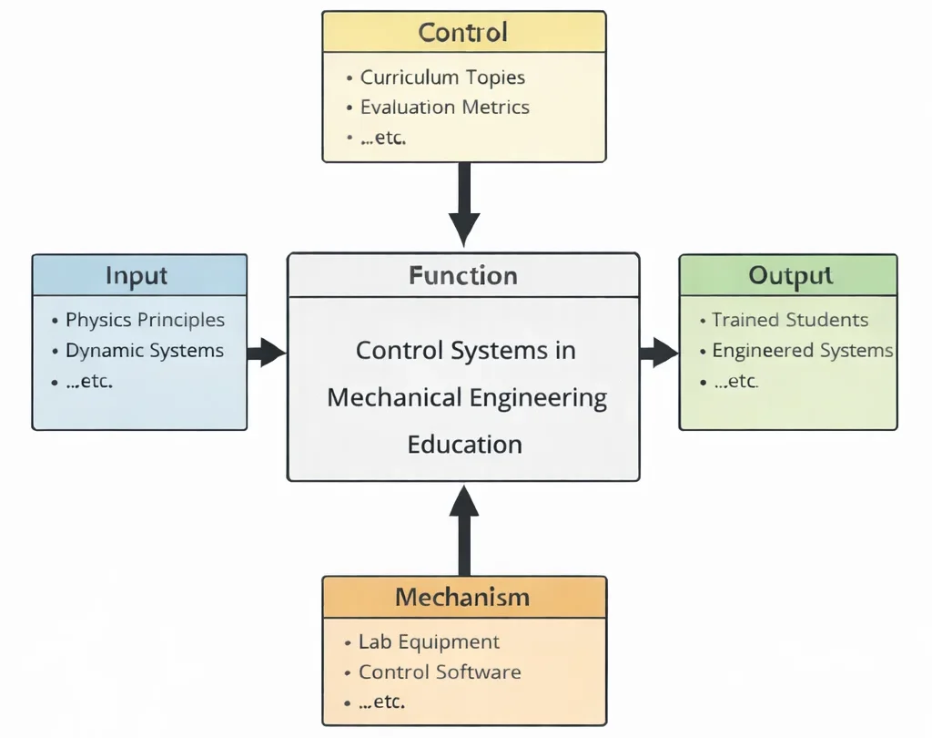
This IDEF0 (Input–Control–Output–Mechanism) diagram summarizes Control Systems in Mechanical Engineering Education as a structured learning process. Inputs on the left—system dynamics and feedback concepts—provide the foundational ideas students must understand to model behavior and design corrective action. Controls at the top—curriculum topics and evaluation criteria—shape the scope and define how learners demonstrate competence, ensuring mastery of both theory and application. The central function, Control Systems in Mechanical Engineering Education, transforms these inputs and controls into practical skill through guided instruction, analysis, and design exercises. Outputs on the right—trained students and stable, optimized systems—represent the intended outcomes: learners who can design controllers and improve system performance, and systems that behave predictably under disturbance and uncertainty. Mechanisms at the bottom—simulation tools and lab setups—enable hands-on exploration, allowing students to test models, tune controllers, and observe real system responses safely and repeatedly.
Control systems play a pivotal role in the functionality and precision of mechanical systems across modern engineering. They allow machines to respond intelligently to inputs and environmental changes by regulating motion, force, or other parameters. A foundational understanding of mechanical engineering underpins the study of control systems, with concepts from solid mechanics and thermodynamics and heat transfer providing essential context for analyzing system dynamics.
In today’s industrial landscape, the integration of automation and robotics is accelerating, making control systems vital for optimizing performance. These systems are particularly important in smart manufacturing and sustainable production, where real-time adjustments are needed to maintain efficiency and quality. Students are exposed to the principles of feedback loops, sensors, and actuators, as well as simulation environments enabled by digital twin technology.
Developing effective control systems requires proficiency in modeling and design tools like CAD, and a strong grasp of system behavior influenced by fluid mechanics and vibration analysis. Control applications extend across diverse sectors including automotive engineering, biomechanics, and robotics. These areas demand precise control to ensure safety, efficiency, and user adaptability.
The discipline also aligns closely with broader themes in industrial and manufacturing technologies. Engineers must consider factors like energy efficiency, quality assurance, and lean manufacturing practices when developing automated processes. The field benefits from advances in 3D printing and materials engineering, which expand the design space and enhance system adaptability.
Students are encouraged to explore interconnected topics such as supply chain logistics, production engineering, and computer-integrated manufacturing to gain a comprehensive view of how control systems fit into larger industrial networks. Concepts from nanotechnology and acoustics also enhance understanding of specialized control applications. Ultimately, the study of control systems empowers students to contribute to innovations in responsive machinery, intelligent devices, and complex automated networks.
About This Interactive Simulator:
This interactive simulator demonstrates closed-loop PID control for a second-order mass-spring-damper mechanical system. By adjusting proportional, integral, and derivative gains alongside system damping, you can observe step-response dynamics, overshoot, and steady-state error elimination in real time.
- Proportional Gain (Kp): Controls step response speed; higher values decrease rise time but increase overshoot.
- Integral Gain (Ki): Accumulates tracking error over time, eliminating steady-state offset while introducing phase lag.
- Derivative Gain (Kd): Predicts future trajectory, damping high-frequency oscillations and stabilizing transient response.
- Solid Line (Controlled Response): Represents active output position vs. target step input.
- Dashed Line (Target Setpoint): Demarcates the target step displacement boundary.
Closed-Loop PID Control & Step Response Simulator
Adjust control gains and mechanical damping below to analyze dynamic step response, rise time, overshoot, and settling time.
System Regulation: Feedback, Stability, and Dynamic Control
Mechanical Engineering – Overview
Frames control as a critical systemic layer that governs performance, operational precision, and dynamic responsiveness across physical machines.
Control Systems in Mechanical Engineering (Current)
Designs real-time feedback mechanisms to regulate motion, thermal state, and fluid dynamics for structural stability and maximum throughput.
Vibrations & Acoustics
Applies active control strategies and tuned mass dampening to attenuate harmonic oscillations and prevent catastrophic structural resonance.
Fluid Mechanics
Regulates volumetric flow rates, pressure head, and fluid power transmission within closed-loop hydraulic and pneumatic actuations.
Thermodynamics
Maintains tight temperature thresholds and thermodynamic energy balance using feedback-controlled heat exchangers and thermal loops.
Mechanical Design
Integrates physical sensors, microcontrollers, and servo actuators directly into solid CAD assemblies for seamless hardware responsiveness.
Manufacturing Engineering
Employs programmable logic controllers and automated feedback loops to maintain micro-scale machining tolerances across factory lines.
Robotics & Automation
Implements real-time kinematic algorithms and trajectory tracking to achieve precise autonomous manipulation in industrial environments.
Automotive Engineering
Controls chassis dynamics, electronic stability, and powertrain efficiency through networked Electronic Control Units (ECUs).
Solid Mechanics
Models structural stiffness and strain limits to prevent dynamic instability and mechanical fatigue during closed-loop loading cycles.
Biomechanical Engineering
Applies adaptive myoelectric control loops to prosthetics and wearable exoskeletons for natural human-machine interaction.
Advanced Materials
Leverages smart piezoelectric and shape-memory materials to achieve high-frequency micro-scale positioning and adaptive damping.
Core Concepts of Control Systems in Mechanical Engineering
Control System Basics
- Definition:
- A control system is a sophisticated framework that governs the behavior of machines, processes, or systems to ensure a desired output is achieved in a reliable and efficient manner. In mechanical engineering, control systems are embedded in everything from household appliances to complex aerospace machinery. These systems act as the central intelligence, enabling machines to respond to varying inputs and external conditions with precision.
- Control systems are categorized based on their responsiveness, accuracy, and complexity. Simple systems might just involve manual adjustments, while advanced systems incorporate artificial intelligence, predictive modeling, and real-time feedback loops.
- Components:
- Sensor:
- Sensors are critical input devices that capture real-time data from the environment or the mechanical system itself. Depending on the application, sensors may measure temperature, pressure, velocity, displacement, vibration, humidity, or fluid level. For instance, in an automotive cruise control system, a speed sensor provides continuous input to maintain the vehicle at a constant speed despite changes in terrain.
- Controller:
- The controller is the decision-making unit that interprets sensor data and determines the necessary action to achieve the setpoint. It compares the measured value with the desired value and computes an error signal. Controllers can range from simple analog circuits to sophisticated microcontrollers and digital signal processors (DSPs). Algorithms like PID (Proportional-Integral-Derivative) or Model Predictive Control are commonly implemented in controllers to ensure stability and performance.
- Actuator:
- Actuators are the output components that execute the control commands from the controller. These devices convert electrical signals into physical movement, such as rotating a shaft, moving a valve, or adjusting a throttle. Types of actuators include electric motors, solenoids, hydraulic cylinders, and pneumatic actuators. The precision and responsiveness of actuators play a significant role in the overall efficiency of the control system.
- Feedback Loop:
- The feedback loop is the heart of a control system. It continuously monitors the output and feeds that data back into the controller for ongoing adjustments. This closed-loop operation is essential for minimizing the difference between actual and desired output. Feedback ensures stability, reduces the effect of disturbances, and allows the system to adapt to changing conditions. Real-world examples include thermostats in HVAC systems and flight control systems in aircraft.
- Sensor:
Types of Control Systems
- Open-Loop Control:
- In an open-loop system, there is no feedback mechanism to adjust the input based on the actual output. The system operates on a fixed set of instructions, assuming ideal conditions. While this simplicity reduces cost and complexity, it also means the system cannot correct itself if disturbances occur. Common examples include microwave ovens, irrigation timers, and traffic light systems with fixed cycles.
- These systems are suitable where precision is less critical or the operating conditions are predictable. However, they often lack adaptability, making them less effective in dynamic or uncertain environments.
- Closed-Loop Control:
- Closed-loop systems, or feedback control systems, dynamically adjust their operation based on real-time output. By continuously comparing actual performance to desired outcomes, these systems can correct deviations and maintain stability. A thermostat is a typical closed-loop system—it turns the heater on or off based on room temperature readings to maintain the setpoint temperature.
- Closed-loop systems are widely used in robotics, automotive systems, aerospace, and industrial automation. They provide better performance, accuracy, and robustness, especially when dealing with variable loads or unpredictable disturbances.
- Linear vs. Nonlinear Control:
- Linear Control: Assumes the relationship between input and output follows linear equations, simplifying analysis and design. These systems can be accurately described using superposition and Laplace transforms. Most traditional PID controllers operate under linear assumptions, making them suitable for a broad range of engineering problems.
- Nonlinear Control: Deals with systems where the relationship between input and output is complex and nonlinear, such as robotic arms, jet engines, or chemical reactors. Nonlinear control methods—such as sliding mode control, Lyapunov stability, and feedback linearization—are essential for ensuring stability and control under nonlinear dynamics.
- Adaptive Control:
- Adaptive control systems are capable of adjusting their parameters in real-time in response to changes in system dynamics or external disturbances. These systems are particularly useful in applications where the system model is not fixed or may change over time. Examples include adaptive cruise control in vehicles and aircraft autopilots that adjust to changing flight conditions.
- Adaptive control represents the frontier of intelligent automation, often integrated with machine learning algorithms to enhance learning capabilities and self-optimization.
Control System Design
- Mathematical Modeling:
- Control system design begins with creating a mathematical model that represents the system's physical behavior. This includes developing differential equations, state-space representations, or transfer functions. Accurate modeling enables engineers to predict how a system will respond under different conditions, facilitating better controller design and system optimization.
- Transfer Functions:
- Transfer functions express the relationship between a system's input and output in the frequency domain. They are instrumental in analyzing system stability, transient response, and frequency characteristics. Tools like Bode plots and Nyquist diagrams help engineers visualize and design control strategies based on transfer functions.
- System Dynamics:
- This refers to how a system evolves over time under various inputs. It encompasses both transient behavior—how a system reacts initially—and steady-state behavior—how the system settles. Understanding dynamics is crucial for tuning controller parameters and predicting system responses to disturbances or changes in setpoints.
- Stability Analysis:
- Stability ensures the system returns to equilibrium after a disturbance. Techniques like Routh-Hurwitz, root locus, and Lyapunov’s method are used for assessing and ensuring stability. A stable system resists oscillations, prevents divergence, and maintains control performance across various operating conditions.
Control Strategies
- Proportional-Integral-Derivative (PID) Control:
- PID controllers are the most widely used control strategy in industry due to their simplicity and effectiveness. They combine three actions: Proportional (corrects the present error), Integral (eliminates steady-state error), and Derivative (predicts future error). Tuning these gains correctly ensures optimal system performance in terms of speed, stability, and accuracy.
- Model Predictive Control (MPC):
- MPC uses a model of the system to predict future outcomes and optimize control actions over a moving time horizon. It considers constraints on inputs and outputs, making it suitable for complex systems like chemical plants, HVAC systems, and self-driving vehicles. MPC can anticipate future disturbances and proactively adjust system behavior.
- Optimal Control:
- Optimal control focuses on finding a control policy that minimizes a specific cost function, such as fuel consumption, time, or energy use. It applies calculus of variations and Pontryagin’s principle to solve dynamic optimization problems. This method is widely used in aerospace, robotics, and process engineering.
- Robust Control:
- Robust control aims to maintain system performance despite uncertainties in the system model or external disturbances. H-infinity and sliding mode control are common techniques. These strategies are critical in safety-critical systems like aircraft and nuclear reactors, where failure is not an option.
Control systems form the foundation of automation, making them integral to modern mechanical engineering. Their applications span industries from manufacturing to transportation and healthcare.
Applications of Control Systems in Mechanical Engineering
Automated Manufacturing
- CNC Machines:
- Computer Numerical Control (CNC) machines are precision manufacturing tools that rely heavily on real-time control systems to perform operations such as milling, drilling, and turning with remarkable accuracy. These systems use feedback mechanisms to continuously monitor position, speed, and load, ensuring that the machine follows exact tool paths specified in the G-code. The integration of feedback from encoders and tachometers allows for immediate correction of deviations, resulting in high repeatability and minimal waste.
- Features:
- Real-time position and velocity feedback allow tools to compensate for mechanical deflection and thermal expansion, ensuring dimensional accuracy even during extended runs.
- High precision and repeatability are vital for industries such as aerospace, automotive, and medical device manufacturing, where tolerances are extremely tight.
- Conveyor Systems:
- Automated conveyor systems are the backbone of modern production and distribution facilities. Controlled by integrated sensors, actuators, and programmable logic controllers (PLCs), these systems handle sorting, routing, and tracking of products in real-time. For instance, sensors can detect product dimensions and weight, triggering diverter arms to send items down specific paths based on criteria such as destination or priority level.
- Example: Logistics centers use sophisticated control systems to manage high-throughput sorting with minimal human intervention, ensuring timely dispatch and delivery.
- Assembly Lines:
- Control systems in assembly lines synchronize operations such as welding, gluing, painting, and fastening. These operations often involve industrial robots that perform tasks with programmable logic, sensors for position and quality verification, and safety interlocks. This automation boosts productivity, enhances worker safety, and allows flexible production of multiple product types without retooling the entire line.
Robotics
- Robotic Arms:
- Modern robotic arms are highly reliant on control systems that handle joint kinematics, trajectory planning, and real-time motion correction. These systems ensure that tasks such as arc welding, material handling, or surgical manipulation are executed with high accuracy and responsiveness. Sensors such as force-torque sensors enhance control by allowing the robot to adjust its motion based on external forces.
- Features:
- Real-time trajectory planning is vital for collaborative robots working in unstructured environments where obstacles or humans are present.
- High-speed and high-precision operations are standard in semiconductor fabrication, micro-assembly, and fine-pick-and-place tasks in electronics manufacturing.
- Humanoid Robots:
- Humanoid robots simulate human movement and interaction through advanced control algorithms that manage complex motion coordination. These systems regulate gait, posture, balance, and arm movement using multiple sensors, including inertial measurement units (IMUs), gyroscopes, and vision systems. Such robots are used in eldercare, customer service, and disaster recovery scenarios where human-like interaction is essential.
- Autonomous Robots:
- Autonomous robots leverage control systems integrated with artificial intelligence to make decisions on navigation, obstacle avoidance, and task prioritization. They interpret input from vision sensors, LiDAR, GPS, and ultrasonic detectors to perform operations with minimal supervision. These robots are widely used in warehouse automation, agriculture, and search-and-rescue operations.
- Example: Kiva robots dynamically adjust routes to avoid collisions and delays while maintaining throughput in massive fulfillment centers.
Aerospace Engineering
- Flight Control Systems:
- In aviation, flight control systems regulate the movement of control surfaces like rudders, ailerons, and elevators to maintain the aircraft’s trajectory. Modern aircraft employ fly-by-wire systems, which replace mechanical linkages with electronic interfaces and software algorithms. These systems continuously adjust the aircraft’s orientation based on sensor input and pilot commands, ensuring stability and maneuverability even in adverse conditions.
- Features:
- Autopilot systems use GPS and inertial navigation systems to automate flight paths, reducing pilot workload and improving flight efficiency.
- Fly-by-wire systems enable adaptive responses, such as automatic stall prevention or crosswind compensation during landing.
- Spacecraft Attitude Control:
- Spacecraft use attitude control systems to orient themselves in three-dimensional space. These systems rely on gyroscopes, star trackers, and reaction wheels to detect and adjust orientation without consuming fuel. Small thrusters can also be used for fine adjustments. Accurate attitude control is essential for tasks such as antenna alignment, solar panel positioning, and scientific observations.
Automotive Industry
- Vehicle Dynamics Control:
- Control systems enhance vehicle safety and performance through technologies such as Anti-lock Braking Systems (ABS), Electronic Stability Control (ESC), and traction control. These systems process data from wheel speed sensors, yaw rate sensors, and accelerometers to dynamically adjust braking and engine power, preventing skidding and rollovers.
- Autonomous Vehicles:
- Self-driving cars use an array of control systems that merge data from radar, LiDAR, ultrasonic sensors, and high-definition maps. These systems plan paths, execute lane changes, manage speed, and detect obstacles, forming the core of autonomous navigation. Control algorithms are built to handle uncertainties like traffic, pedestrians, and weather changes.
- Engine Control:
- Electronic Control Units (ECUs) regulate fuel injection, ignition timing, air-fuel ratio, and exhaust gas recirculation to optimize power output and minimize emissions. Adaptive control strategies are used to meet environmental regulations and maximize fuel economy under various driving conditions.
HVAC Systems (Heating, Ventilation, and Air Conditioning)
- Temperature Regulation:
- Thermostatic control systems maintain desired indoor temperatures by modulating heating and cooling devices. PID controllers are commonly used to achieve fast and stable temperature control, preventing overshooting and reducing energy consumption.
- Energy Optimization:
- Advanced control systems incorporate occupancy sensors, outdoor weather forecasts, and building usage patterns to dynamically adjust HVAC operation. These systems reduce energy costs by minimizing usage during unoccupied hours and optimizing ventilation based on indoor air quality metrics.
Renewable Energy Systems
- Wind Turbines:
- Wind turbine control systems manage rotor speed, blade pitch angle, and yaw direction to maximize energy production while protecting the structure from high wind loads. These systems balance mechanical stresses with power output optimization, particularly in variable wind conditions.
- Solar Tracking Systems:
- Control mechanisms continuously adjust the orientation of solar panels to face the sun throughout the day, increasing energy capture by 20–30% compared to fixed systems. These trackers use algorithms based on solar geometry, weather data, and real-time feedback from light sensors.
Industrial Processes
- Process Control:
- In industries like chemical processing, pharmaceuticals, and petrochemicals, control systems regulate variables such as pressure, temperature, flow rate, and chemical concentration. Distributed Control Systems (DCS) and Supervisory Control and Data Acquisition (SCADA) platforms provide centralized monitoring and decentralized control across large-scale operations.
- Pumps and Valves:
- Control systems ensure smooth and energy-efficient operation of fluid transport in pipelines. Variable Frequency Drives (VFDs) adjust pump speeds based on demand, while smart valves precisely regulate flow and pressure to maintain system integrity.
Seismic Engineering
- Active Vibration Control:
- Buildings and bridges are equipped with systems like tuned mass dampers and semi-active control devices that detect and counteract seismic vibrations in real-time. These systems enhance structural resilience, reduce oscillations, and improve occupant safety during earthquakes.
Medical Devices
- Surgical Robots:
- Surgical robots integrate precise control mechanisms that interpret surgeon inputs and translate them into minimally invasive actions. High-speed feedback loops ensure that hand tremors are filtered and motion scaling is applied for microsurgery, increasing precision and reducing recovery times.
- Prosthetics:
- Modern prosthetic limbs incorporate adaptive control systems that use electromyography (EMG) signals to interpret user intent. These systems enable fluid motion, grip adjustment, and even tactile feedback, vastly improving the quality of life for amputees.
Emerging Technologies in Control Systems in Mechanical Engineering
Artificial Intelligence (AI) and Machine Learning
- Artificial Intelligence (AI) and Machine Learning (ML) are transforming control systems by enabling them to go beyond rule-based logic and evolve into intelligent, self-improving mechanisms. Traditional control systems rely on preprogrammed models, whereas AI-enhanced systems learn from data, identify patterns, and adapt their behavior accordingly. In mechanical engineering, AI algorithms can analyze vast datasets from sensors and actuators to predict optimal responses in dynamic environments.
- Applications:
- Autonomous vehicles: AI enables real-time decision-making for steering, speed adjustment, and obstacle avoidance based on visual inputs and traffic data.
- Predictive maintenance: ML models trained on historical sensor data can forecast equipment failures, allowing timely intervention and reducing unplanned downtime in industrial systems.
Internet of Things (IoT) Integration
- The integration of the Internet of Things (IoT) with control systems has enabled unprecedented levels of connectivity and data exchange. Sensors embedded in machines, tools, and infrastructure continuously collect data on system parameters such as temperature, pressure, and vibration. This information is then transmitted via IoT networks to cloud platforms or local control units for monitoring and decision-making. The result is an intelligent, interconnected ecosystem that supports remote diagnostics, real-time updates, and system optimization.
- Example: In Industry 4.0 environments, smart manufacturing systems utilize IoT-enabled control architectures to track production metrics, adjust machine operations in real-time, and ensure quality control with minimal human intervention.
Edge Computing
- Edge computing is revolutionizing how data is processed within control systems by shifting computation from centralized servers to local edge devices. This reduces latency, minimizes bandwidth requirements, and enhances system responsiveness. Edge computing is particularly critical in time-sensitive applications where even milliseconds matter, such as in robotics and autonomous systems. Unlike cloud-based models, edge computing can maintain functionality during network disruptions, improving reliability in critical systems.
- Applications:
- Real-time robotics: Edge devices embedded in robotic arms or mobile robots allow instant decision-making for navigation and task execution.
- Autonomous drones: Edge-based control systems enable on-board flight adjustments based on sensor inputs like GPS, barometers, and cameras, even without constant internet connectivity.
Digital Twins
- Digital twins are virtual models that replicate the physical behavior and performance of mechanical systems in real time. These replicas are connected to the real-world counterparts via data streams, allowing engineers to simulate various scenarios, test new control strategies, and detect faults before they occur. By comparing actual system data with expected behavior, digital twins provide actionable insights into system performance and areas for improvement.
- Applications:
- Predictive maintenance: In industrial plants, digital twins monitor the health of machines and predict failures, enabling proactive servicing.
- Aerospace control: Engineers test control algorithms on digital replicas of aircraft to ensure robustness and safety before implementation on actual hardware.
Quantum Control
- Quantum control explores the use of quantum computing and quantum algorithms to solve complex control optimization problems with unprecedented speed and accuracy. These systems leverage principles such as superposition and entanglement to process massive amounts of data in parallel. While still in the experimental phase, quantum control holds promise for highly nonlinear and multi-variable systems that are difficult to model with conventional methods.
Adaptive and Self-Tuning Controllers
- Adaptive and self-tuning controllers represent a significant advancement over traditional control systems by automatically modifying control parameters in response to changing system dynamics. These controllers continuously monitor performance metrics and adjust gains or control laws to maintain stability and accuracy. This is particularly useful in systems with high uncertainty or where manual tuning is impractical, such as in mobile robotics or variable-load machinery.
Challenges in Control Systems in Mechanical Engineering
Complexity of Dynamic Systems:
- One of the foremost challenges in control systems is managing the inherent complexity of dynamic systems, especially those that exhibit nonlinear, time-varying, or chaotic behavior. Real-world mechanical systems rarely conform to ideal linear models; they often involve friction, hysteresis, backlash, or varying loads, all of which complicate accurate modeling and prediction. Designing control algorithms that can robustly handle such behaviors requires advanced techniques like nonlinear control, fuzzy logic, and neural networks. Furthermore, the validation of these control schemes through simulation and experimental testing is labor-intensive and computationally demanding.
Scalability:
- As systems grow in scale and complexity—such as smart factories, autonomous vehicle fleets, or interconnected HVAC systems—control engineers must devise solutions that can scale without sacrificing performance. Coordinating multiple subsystems with differing dynamics and latency constraints introduces synchronization issues, conflicts in control objectives, and potential system instability. Hierarchical and distributed control architectures have emerged to address these problems, but they introduce new difficulties in coordination and system design. Scalable control systems must also remain fault-tolerant and maintain real-time responsiveness under variable loads.
Cybersecurity:
- With the rise of Internet-connected industrial equipment and cloud-based monitoring, cybersecurity has become a critical challenge in control systems. Unauthorized access to control nodes, tampering with sensor data, or denial-of-service attacks can cause system malfunctions with potentially catastrophic consequences. Industrial control systems in sectors like energy, transportation, and manufacturing are frequent targets of cyber threats. Engineers must implement multi-layered security protocols, encryption standards, and intrusion detection systems to mitigate these risks. Real-time anomaly detection and secure communication protocols are now integral to modern control architecture design.
Integration with Legacy Systems:
- Many industrial environments operate with a mixture of old and new technologies. Integrating state-of-the-art control systems with legacy hardware and software is a significant challenge. Legacy systems may use outdated communication protocols, limited processing power, or hardware that lacks modern interfaces, which can hinder seamless interoperability. This often necessitates the use of middleware, protocol converters, or custom adapters to bridge the technological gap. Balancing modernization with cost-effectiveness, safety, and reliability requires careful planning, reverse engineering, and iterative testing.
Real-Time Constraints:
- Control systems in applications such as robotics, autonomous vehicles, aerospace systems, and industrial automation must meet strict real-time requirements. Any delay in data processing or actuator response can lead to performance degradation, system instability, or even hazardous failures. Engineers must ensure that control algorithms execute within tight timing constraints, often at the millisecond or microsecond scale. This challenge is exacerbated in distributed systems where communication latency and jitter can affect coordination. Solutions include real-time operating systems (RTOS), deterministic networking, and hardware acceleration using FPGAs or GPUs.
Future Directions of Control Systems in Mechanical Engineering
Smart Factories:
- The evolution of control systems is poised to redefine the manufacturing landscape through the rise of smart factories. These facilities are characterized by the integration of artificial intelligence, machine learning, real-time data analytics, and interconnected machinery to enable self-optimizing production lines. Control systems in smart factories will not only regulate individual machines but also coordinate entire manufacturing ecosystems, adjusting workflows in real time to maximize efficiency and reduce downtime. Predictive maintenance algorithms will forecast component failures before they occur, reducing interruptions. Moreover, smart factories will incorporate digital twins to simulate operations and identify bottlenecks before they arise. Industry 4.0 initiatives are driving this transformation, promoting agile, scalable, and sustainable production environments.
Autonomous Systems:
- Autonomous systems such as self-driving cars, unmanned aerial vehicles (UAVs), and robotic assistants rely heavily on advanced control algorithms for perception, decision-making, and actuation. These systems must operate reliably in dynamic, uncertain environments while meeting safety and performance standards. Future developments will focus on hybrid control strategies that combine model-based predictive control with AI-driven learning algorithms. Autonomous systems will increasingly feature swarm intelligence, enabling cooperative behavior among fleets of vehicles or drones. They will also integrate multi-modal sensor fusion and edge computing to ensure fast, localized control decisions. As autonomy becomes more mainstream, regulatory frameworks and ethical considerations will also shape control system design.
Energy-Efficient Systems:
- In response to global climate concerns and rising energy costs, control engineers are developing sophisticated energy-efficient systems across mechanical applications. These include optimizing motor control in industrial drives, regulating HVAC systems based on occupancy patterns, and employing variable speed drives in pumps and fans. Control strategies such as dynamic energy modeling, demand response, and energy-aware scheduling are becoming essential. Integration with renewable energy sources—such as wind, solar, and geothermal—requires control systems that can adapt to variable supply and coordinate with grid demand. Smart grids and microgrids will also depend on real-time control for load balancing and power quality assurance. Future systems will focus on achieving net-zero emissions while maintaining operational efficiency.
Space Exploration:
- Space missions demand highly reliable and adaptive control systems capable of functioning in extreme and unpredictable environments. Future control systems will support autonomous spacecraft navigation, real-time trajectory correction, and long-duration habitat regulation. They must withstand communication delays, radiation exposure, and mechanical failures. For interplanetary travel, control systems will incorporate AI to manage onboard diagnostics and decision-making. In extraterrestrial habitats, such as lunar or Martian bases, they will regulate life support systems, power distribution, and robotic maintenance. These developments will require advances in fault-tolerant control, multi-agent coordination, and resilient feedback architectures capable of sustaining operations with limited human oversight.
Human-Machine Collaboration:
- The future of control systems will be deeply intertwined with human-machine collaboration. From collaborative robots (cobots) in manufacturing to wearable exoskeletons in healthcare and rehabilitation, control systems must safely interpret human intent and respond in real time. Techniques such as electromyography (EMG) signal processing, brain-computer interfaces, and haptic feedback are advancing to enhance interaction quality. These systems must be intuitive, adaptive, and responsive to varying user needs and skill levels. Shared control frameworks—where control responsibilities shift fluidly between the human and machine—will become more prominent. This paradigm supports safer and more effective joint operation, particularly in domains such as assisted living, disaster response, and remote surgery.
Why Study Control Systems in Mech Engineering
Regulating Dynamic Mechanical Systems
Control systems are essential for managing the behavior of dynamic mechanical systems. Students learn how to maintain stability and performance under varying conditions. This knowledge is critical in fields such as robotics, automation, and automotive engineering.
Feedback, Sensors, and Actuators
Students study how feedback loops use sensors to monitor outputs and actuators to correct deviations. This enables systems to adjust in real time. These principles are foundational in designing intelligent and responsive machines.
Mathematical Modeling and System Analysis
The course introduces transfer functions, differential equations, and control diagrams. Students learn to model and simulate system behavior using tools like MATLAB. This analytical approach supports precise system design.
Applications in Modern Mechanical Systems
Control systems are used in HVAC, vehicle cruise control, aerospace systems, and industrial machinery. Students explore how control theory enhances safety, efficiency, and automation. This opens doors to interdisciplinary engineering roles.
Preparing for Mechatronics and Smart Technologies
As mechanical systems become more digitized, control systems bridge the gap between mechanics and electronics. Students gain skills applicable to mechatronics and cyber-physical systems. This prepares them for roles in advanced manufacturing and intelligent design.
Control Systems in Mechanical Engineering: Conclusion
Control systems serve as the backbone of modern mechanical engineering, orchestrating the seamless operation of machines, processes, and entire infrastructures. They enable engineers to regulate variables such as motion, temperature, force, and energy across a broad spectrum of applications—from automated factories to self-driving vehicles, surgical robots, aerospace systems, and smart energy grids. By translating sensor data into actionable feedback and decision-making, control systems ensure precision, stability, and efficiency in dynamic environments.
In industrial contexts, control systems elevate productivity by optimizing assembly lines, coordinating robotic operations, and reducing waste through predictive maintenance. In transportation, they govern everything from cruise control to electric vehicle powertrains and adaptive braking systems. In energy, they balance fluctuating demands while integrating renewables with legacy infrastructure. Healthcare benefits too, as robotic surgery, assistive devices, and drug delivery systems all rely on advanced control techniques to function reliably and safely.
The future of control systems is deeply intertwined with emerging technologies. Artificial intelligence enables adaptive control that evolves through experience; the integration of cyber-physical systems and IoT allows for decentralized decision-making and real-time responsiveness; edge computing brings faster processing to the point of action; and quantum computing offers the potential for solving optimization problems previously deemed intractable. These innovations are reshaping how engineers design and deploy control architectures across disciplines.
Furthermore, the growing complexity of modern systems demands interdisciplinary collaboration, combining mechanical engineering with data science, systems engineering, cybersecurity, and human factors. Educational programs and research initiatives are increasingly emphasizing this convergence to prepare future engineers for a rapidly evolving technological landscape.
As control systems grow smarter, more autonomous, and more integrated, they will be essential not just for operational efficiency but also for sustainability, resilience, and safety. Their role in shaping the next generation of engineered systems cannot be overstated—they are the invisible force driving intelligent, adaptive, and transformative solutions in the 21st century and beyond.
Control Systems in Mechanical Engineering: Frequently Asked Questions (FAQ)
This FAQ highlights core concepts, methods, and applications of control systems as they apply to modern mechanical engineering.
1. What is a control system in mechanical engineering?
In mechanical engineering, a control system is a combination of components that regulates the behavior of a machine or process to achieve a desired output. It uses inputs such as sensor measurements, compares them to a reference or setpoint, and then commands actuators to correct any deviation, ensuring stability, accuracy, and performance.
2. What is the difference between open-loop and closed-loop control systems?
An open-loop control system sends commands to a mechanical device without using feedback, so it does not measure whether the desired result is achieved. A closed-loop (feedback) control system continuously measures the output using sensors, compares it to a setpoint, and adjusts the actuator commands to correct errors. Closed-loop systems are more accurate and robust to disturbances but are also more complex to design and tune.
3. What is a PID controller and why is it widely used in mechanical control systems?
A PID controller is a feedback controller that combines Proportional (P), Integral (I), and Derivative (D) actions to reduce error between a desired setpoint and the measured output. The proportional term reacts to the current error, the integral term accumulates past errors to eliminate steady-state offset, and the derivative term anticipates future error based on its rate of change. PID controllers are widely used in mechanical systems because they are conceptually simple, work well for many processes, and can be implemented in both analog and digital forms.
4. How are mechanical control systems mathematically modeled?
Mechanical control systems are typically modeled using differential equations that describe how forces, motion, and energy interact in the system. These equations can be converted into transfer functions in the Laplace domain or into state-space models that capture system dynamics in matrix form. Block diagrams are then used to represent how components such as sensors, controllers, and actuators are interconnected, allowing engineers to analyze system response and design appropriate control strategies.
5. What roles do sensors and actuators play in control systems for mechanical engineering?
Sensors measure key physical quantities such as position, speed, acceleration, force, pressure, and temperature, converting them into electrical signals for the controller. Actuators, such as electric motors, hydraulic cylinders, pneumatic valves, and servo mechanisms, convert the controller's output signals into mechanical motion or force. Together, sensors and actuators form the essential feedback and action loop that enables a mechanical control system to monitor performance and apply corrections.
6. Why is stability important in control systems, and how is it assessed?
Stability is crucial because an unstable control system can cause oscillations, excessive vibration, or even destructive runaway motion in mechanical equipment. Stability is assessed by analyzing the system's dynamic response using tools such as characteristic equations, root locus plots, Bode plots, and Nyquist diagrams. A stable system returns to equilibrium or a steady response after a disturbance, while an unstable system diverges or oscillates without bound.
7. What are some real-world applications of control systems in mechanical engineering?
Control systems appear in many mechanical engineering applications, including cruise control and engine management in vehicles, temperature and flow control in HVAC and process plants, robotic manipulators and autonomous vehicles, vibration control in structures and machinery, and motion control in CNC machines and industrial automation. In each case, control strategies are used to achieve precise, safe, and efficient operation under varying conditions.
8. How does digital control differ from analog control in mechanical systems?
Analog control uses continuous-time signals and analog electronic circuits to implement controllers, while digital control uses microcontrollers, PLCs, or embedded computers that process sampled data using algorithms. Digital control makes it easier to implement complex strategies, adapt parameters in real time, log data, and integrate with networks, but it also requires attention to sampling, quantization, and computational delays to maintain good performance and stability.
9. What skills and tools should students develop to work with control systems in mechanical engineering?
Students should build strong foundations in calculus, differential equations, linear algebra, dynamics, and system modeling, along with practical skills in programming and simulation tools such as MATLAB or Python. They should learn how to interpret Bode and root locus plots, tune PID controllers, design basic state-space controllers, and work with microcontrollers, sensors, and actuators in laboratory or project settings. Communication and documentation skills are also important for explaining design choices and collaborating with multidisciplinary teams.
Control Systems in Mechanical Engineering Practice & Evaluation Module
Section 1: Interactive Foundational Concept Reviews
1. What is a control system in the context of mechanical engineering, and why is it critical?
Answer: A control system manages the behavior of devices and processes by receiving inputs, processing the data, and adjusting outputs accordingly. In mechanical engineering, control systems enable machinery to respond dynamically to changing conditions—like regulating temperature, controlling speed, or stabilizing a robotic arm. This is critical because it ensures safety, increases efficiency, maintains precision, and enables automation across modern industrial processes, automotive systems, and robotics.
2. How do open-loop and closed-loop control systems differ, and what are real-world examples of each?
Answer: An open-loop control system operates without feedback; it executes a set of instructions without measuring output performance. An example is a simple washing machine timer that runs for a predefined duration. In contrast, a closed-loop system uses feedback to compare the actual output with the desired setpoint, adjusting actions accordingly. A household thermostat exemplifies this principle, continually measuring room temperature and switching a heater on or off to maintain a target temperature. Closed-loop systems offer more accurate and stable control, which is crucial for complex tasks like automated manufacturing lines and aerospace navigation.
3. Why is feedback important in control systems, and what roles do sensors play in feedback loops?
Answer: Feedback ensures a control system can monitor its output and make real-time adjustments to stay close to the desired setpoint. Sensors are at the heart of this process: they collect data—like temperature, pressure, position, or velocity—and feed it back into the controller. This allows the system to detect discrepancies between the target and current state. For instance, in an automotive cruise control system, sensors measure vehicle speed and compare it to the set speed, prompting the controller to adjust the throttle for a consistent driving experience.
4. What are proportional, integral, and derivative (PID) controllers, and how do they regulate system behavior?
Answer: A PID controller is a fundamental control algorithm that combines three actions to maintain stability and reduce error:
• Proportional (P): Responds proportionally to the current error. Larger error yields a stronger response.
• Integral (I): Accounts for accumulated error over time, eliminating steady-state offset.
• Derivative (D): Predicts future error based on its rate of change, dampening overshoot.
When tuned correctly, these three components ensure the control action is precise, quick to adjust, and minimizes oscillations around the setpoint.
5. In what ways have control systems influenced the evolution of robotics and automated manufacturing?
Answer: Control systems lie at the core of robotics, allowing precise movements and interactions with the environment. They enable robotic arms to move along exact trajectories, adapt grip force, or balance on uneven surfaces. In automated manufacturing, control loops coordinate conveyor speeds, monitor product quality, and synchronize complex tasks across multiple robots. This synergy yields higher consistency, faster throughput, and lower operational costs while facilitating real-time error correction.
6. What challenges do engineers face when designing control systems for dynamic environments?
Answer: Dynamic environments present uncertainties and disturbances—such as vibrations, fluctuating loads, or changing temperatures—that the control system must accommodate. Engineers must account for sensor inaccuracies, non-linear behaviors, and potential time delays in system response. Designers employ techniques like gain scheduling, advanced filtering, or adaptive control to address these issues, verifying safety through rigorous modeling and hardware simulation.
7. How do modern control systems leverage digital technology and embedded computing?
Answer: Advances in microcontrollers, digital signal processors, and programmable logic controllers (PLCs) enable complex algorithms—like predictive control or machine learning—to run in real-time. Digital technology offers high-speed processing, robust data storage, and flexible programming, allowing control loops to adapt quickly and manage multiple inputs simultaneously, supporting smart manufacturing setups under Industry 4.0.
8. Why is system modeling critical to control design, and what software tools are utilized?
Answer: System modeling helps engineers predict how a machine or process will respond to various inputs and disturbances before building physical prototypes. Models capture essential dynamics—mass, damping, stiffness, and fluid properties. Mechanical engineers use mathematical methods like differential equations and state-space representations, alongside computational tools such as MATLAB/Simulink, to refine control parameters efficiently.
9. How do safety-critical applications shape control system design and validation?
Answer: In safety-critical contexts like aerospace or medical technology, system failure can lead to catastrophic outcomes. Control systems undergo rigorous design reviews, fault-tolerant strategies, and redundancy measures (such as triple-modular redundant processing channels). Software validation, hardware-in-the-loop (HIL) testing, and stringent certification standards (like DO-178C or ISO 26262) guarantee reliable fail-safe operation.
10. What emerging trends will influence the future landscape of mechanical control engineering?
Answer: Emergent trends include the integration of machine learning for adaptive self-tuning control, cloud-edge control networks with wireless sensor arrays, and predictive analytics for real-time maintenance. These advancements support autonomous vehicle navigation, swarm robotics, and self-optimizing industrial plants, requiring engineers to possess strong multidisciplinary software and system modeling capabilities.
Section 2: Interactive Analytical & Scenario-Based Evaluations
1. How do control systems act as the central intelligence behind modern machines versus binary mechanisms?
Answer: Control systems continuously monitor inputs, compare them against a desired setpoint, and adjust outputs to achieve stable, precise operation—even under changing conditions. Unlike a simple on/off mechanism that provides a single binary response, control systems use feedback from sensors to refine how a machine responds. This real-time adjustment prevents overshooting, compensates for external disturbances, and optimizes dynamic response.
2. What makes feedback loops so critical in mechanical engineering efficiency and safety?
Answer: Feedback loops continuously regulate a system’s behavior by measuring output and comparing it to the target. When discrepancies arise, the control system initiates corrective actions. This dynamic interaction guards against unstable or drifting operations, such as an assembly line conveyor running too fast or a drone losing altitude. Efficiency improves because the system rapidly corrects itself, minimizing energy waste and preventing catastrophic mechanical divergence.
3. Why are open-loop architectures still specified despite lacking feedback error-correction?
Answer: Open-loop systems are simpler, cheaper, and easier to implement when high precision or adaptability isn’t critical. The primary trade-off is limited accuracy—no real-time adjustments occur if operating conditions deviate from assumptions. Engineers weigh these drawbacks against budget, operational complexity, and safety mandates; routine, low-risk tasks often remain cost-effective under open-loop control.
4. How has real-time digital computing transformed traditional feedback control strategies?
Answer: Microcontrollers and embedded DSPs run complex calculations in real time, enabling advanced techniques like Model Predictive Control (MPC), adaptive gain-scheduling, and neural network controllers. These digital frameworks handle system constraints, multivariable interactions, and non-linear dynamics far beyond the physical capability of traditional analog or pneumatic controllers.
5. In what ways do sensors, controllers, and actuators interact to close a physical loop?
Answer: Sensors capture physical variables (position, temperature, force) and convert them into electrical signals for the controller. The controller calculates error relative to the setpoint and sends control signals to actuators (electric motors, hydraulic valves, solenoids). The actuators exert mechanical work on the plant, altering its state, which is immediately re-measured by the sensors to complete the loop.
6. Why is stability central in control design, and how do tools prevent destructive oscillations?
Answer: Stability ensures that a system returns to equilibrium after a disturbance rather than exhibiting divergent oscillations or destructive runaway motion. Engineers analyze pole locations using Laplace-domain root locus, Bode frequency response plots, and Nyquist criteria to tune control gains (such as PID parameters) for adequate phase and gain margins.
7. How do advanced techniques like Model Predictive Control (MPC) differ from classical PID control?
Answer: While classical PID generates control actions based purely on past and present tracking error, MPC utilizes an internal dynamic model of the plant to forecast future system states over a finite prediction horizon. MPC solves an optimization problem at each timestep, enforcing explicit physical constraints on actuators and state variables before applying the optimal control input.
8. Why is multidisciplinary integration vital for engineering modern mechatronic control solutions?
Answer: Modern control systems integrate mechanical structures, electronic circuits, embedded firmware, and algorithmic software. Mechanical engineers ensure structural integrity and dynamic balance, electrical engineers optimize sensor-actuator interfacing and signal conditioning, and software specialists build real-time control routines. Seamless collaboration ensures hardware physical limits match controller bandwidth and drive electronics.
Section 3: Numerical Problems with Solutions
-
A unity feedback control system has an open-loop transfer function G(s) = 20 / (s(s + 5)). Determine the closed-loop transfer function T(s), the natural frequency (ωn), and the damping ratio (ζ).
Answer:Step 1: Formulate Closed-Loop Transfer Function T(s) = G(s) / (1 + G(s))
T(s) = [20 / (s(s + 5))] / [1 + 20 / (s(s + 5))] = 20 / (s2 + 5s + 20)
Step 2: Compare to Standard Second-Order Form: ωn2 / (s2 + 2ζωns + ωn2)
ωn2 = 20 → ωn = √20 = 4.472 rad/s
2ζωn = 5 → ζ = 5 / (2 × 4.472) = 5 / 8.944
Damping Ratio ζ = 0.559 (Underdamped)
-
For a first-order thermal system modeled by transfer function G(s) = 4 / (3s + 1), calculate the steady-state tracking error ess for a unit step input R(s) = 1/s under unity feedback.
Answer:Step 1: Calculate Position Error Constant (Kp = lims→0 G(s))
Kp = lims→0 [4 / (3s + 1)] = 4 / 1 = 4
Step 2: Calculate Steady-State Error ess = 1 / (1 + Kp)
ess = 1 / (1 + 4) = 1 / 5 = 0.20
Steady-State Error ess = 0.20 (20%)
-
A proportional-only controller (Kp = 12) is used to control a motor with plant transfer function Gp(s) = 1 / (s + 2). Determine the closed-loop pole location and the time constant (τ) of the closed-loop system.
Answer:Step 1: Characteristic Equation 1 + Kp × Gp(s) = 0
1 + 12 / (s + 2) = 0 → s + 2 + 12 = 0 → s + 14 = 0
Closed-Loop Pole location: s = -14
Step 2: Calculate System Time Constant τ = 1 / |pole|
Time Constant τ = 1 / 14 = 0.0714 seconds (71.4 ms)
-
Given a second-order system with natural frequency ωn = 10 rad/s and damping ratio ζ = 0.6, calculate the peak overshoot percentage (%Mp) and peak time (tp).
Answer:Step 1: Calculate Peak Overshoot %Mp = exp(−ζπ / √(1 − ζ2)) × 100
Exponent = −(0.6 × π) / √(1 − 0.36) = −1.88496 / 0.8 = −2.3562
%Mp = exp(−2.3562) × 100 = 0.09478 × 100 = 9.48%
Step 2: Calculate Peak Time tp = π / (ωn × √(1 − ζ2))
tp = π / (10 × 0.8) = 3.14159 / 8 = 0.393 seconds
-
An analog position sensor produces 0 to 5 V corresponding to 0 to 180° shaft rotation. If a 10-bit Analog-to-Digital Converter (ADC) processes this signal, calculate the resolution in volts per bit and angular degrees per LSB bit.
Answer:Step 1: Determine total ADC states for 10 bits (210 = 1024)
Step 2: Voltage Resolution = Vref / 2N
Voltage Resolution = 5.0 V / 1024 = 0.00488 V/bit (4.88 mV/bit)
Step 3: Angular Resolution = Range / 2N
Angular Resolution = 180° / 1024 = 0.1758° per LSB
-
Determine the range of proportional gain K for system stability using the Routh-Hurwitz criterion for characteristic equation: s3 + 6s2 + 11s + K = 0.
Answer:Step 1: Construct Routh Array
Row s3: 1 , 11
Row s2: 6 , K
Row s1: b1 = (6 × 11 − 1 × K) / 6 = (66 − K) / 6
Row s0: c1 = K
Step 2: Enforce First Column Positivity for Stability
1) K > 0
2) (66 − K) / 6 > 0 → 66 − K > 0 → K < 66
Gain Range for Stability: 0 < K < 66
-
A PID controller has gains Kp = 4, Ki = 2 s-1, and Kd = 0.5 s. Compute the control output u(t) at t = 2 s if the error signal is e(t) = 3t. Assume zero initial integral accumulation.
Answer:Step 1: Calculate Error, Integral, and Derivative at t = 2
e(2) = 3 × 2 = 6
∫ e(t) dt from 0 to 2 = ∫ 3t dt = [1.5 t2]02 = 1.5 × 4 = 6
de(t)/dt = d(3t)/dt = 3
Step 2: Evaluate PID Control Equation: u(t) = Kpe + Ki∫e dt + Kd(de/dt)
u(2) = (4 × 6) + (2 × 6) + (0.5 × 3) = 24 + 12 + 1.5
Control Output u(2) = 37.5 units
-
A hydraulic actuator with a piston area A = 0.005 m2 is supplied with fluid at pressure P = 10 MPa. If fluid flow rate is controlled to Q = 2.5 × 10⁻⁴ m3/s, calculate the output mechanical power delivered by the actuator.
Answer:Step 1: Calculate Hydraulic Power (Pmech = P × Q)
P = 10 × 106 Pa, Q = 2.5 × 10⁻⁴ m3/s
Pmech = (10 × 106 N/m2) × (2.5 × 10-4 m3/s) = 2,500 W
Delivered Mechanical Power = 2.50 kW