
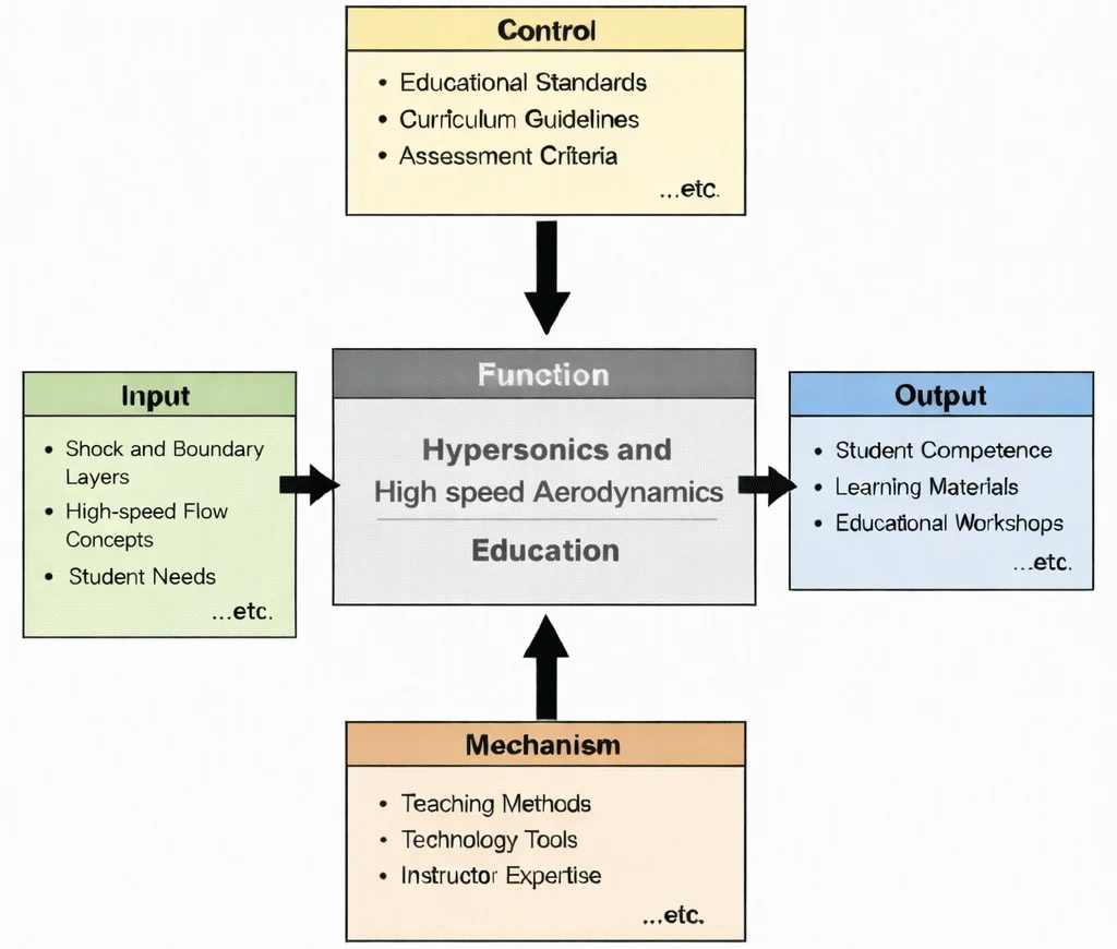
IDEF0 functional decomposition of Hypersonics and High-Speed Aerodynamics Education: non-equilibrium high-temperature flow inputs governed by aerospace design standards, transformed via high-enthalpy shock-tunnel facilities and multi-physics CFD models into verified aerothermal analysis competencies.

Hypersonics and high-speed aerodynamics: resolving the coupled aerothermodynamic interactions between high-enthalpy bow shock discontinuities, entropy layers, and viscous surface heating across Mach 5+ flight regimes.
The illustration shows a sleek high-speed aircraft blasting ahead with bright exhaust trails, surrounded by spiral-like flow structures that suggest compressed air, shock interactions, and rapidly changing pressure fields. The dashboard-style charts and instruments evoke wind-tunnel testing, computational simulations, and performance monitoring used in hypersonic research. Overall, the image conveys the core challenges of hypersonic flight—controlling airflow at extreme speeds, managing aerodynamic forces and stability, and coping with intense thermal loads—central themes in high-speed aerodynamics and aerospace engineering.
Extreme Velocity Flow and Thermal Interaction Systems
Aerospace & Aeronautical – Overview
Connects high-speed regimes with the broader system of aerospace motion, atmospheric entry trajectories, and vehicle control envelopes.
Hypersonics & High-Speed Aerodynamics (Current Module)
Examines Mach 5+ flow behaviour where extreme velocity introduces strong bow shock interactions, real gas chemical dissociation, and intense stagnation heating.
Aerodynamics
Provides the foundational continuum fluid mechanics extended here to incorporate high Mach number compressibility and shock wave formation.
Flight Mechanics
Governs 6-DOF stability and trajectory optimization when aerodynamic forces become highly non-linear due to shock displacement and low lift-to-drag ratios.
Propulsion Systems
Enables sustained hypersonic cruise through air-breathing scramjets, dual-mode ramjets, and high-thrust rocket integration.
Celestial Mechanics
Becomes dominant once vehicles transition beyond sensible atmospheric boundary limits into orbital insertion trajectories.
Aero Materials Science
Determines surface material resistance to thermal shock, oxidation, active ablation, and 2000°C+ leading-edge temperatures.
Aerospace Structures
Must accommodate extreme differential thermal expansion and extreme shock-induced acoustic vibrations without loss of structural integrity.
Aero Control Systems & Robotics
Requires ultra-fast closed-loop feedback algorithms to maintain pitch, roll, and yaw stability during rapid high-Mach maneuvers.
Avionics
Processes real-time sensor streams and manages guidance controls through high-temperature plasma signal attenuation layers.
Spacecraft Engineering
Connects hypersonic aerothermal heating models directly to atmospheric entry, descent, and landing (EDL) sequence design.
Satellite Technology
Relates to aerocapture maneuvers and thermal shield sizing for returning payload capsules from Earth orbit.
Key Characteristics of Hypersonic Flight
A hypersonic glide vehicle (HGV) cruises at Mach \(M_\infty = 8.0\) at an altitude of \(32.0 \text{ km}\) (\(32,000 \text{ m}\)) where ambient static temperature is \(T_\infty = 228.65 \text{ K}\), atmospheric density is \(\rho_\infty = 0.01355 \text{ kg/m}^3\), and local acoustic sound speed is \(a_\infty = 303.1 \text{ m/s}\). Calculate total freestream velocity \(V_\infty\), total stagnation temperature \(T_0\) under calorically perfect gas assumptions (\(\gamma = 1.40\)), and evaluate the stagnation heat flux \(\dot{q}_s\) for a spherical nose cap of radius \(R_n = 0.050 \text{ m}\) using the semi-empirical Sutton-Graves stagnation heat transfer relation:
$$\dot{q}_s = k \sqrt{\frac{\rho_\infty}{R_n}} V_\infty^3 \quad \left( k = 1.7415 \times 10^{-4} \text{ kg}^{0.5}\cdot\text{m}^{-1} \text{ for Earth's atmosphere} \right)$$Sequential Derivation & Calculation:
Step 1: Calculate freestream flight velocity \(V_\infty\):
$$V_\infty = M_\infty \cdot a_\infty = 8.0 \times 303.1 \text{ m/s} = \mathbf{2,424.8 \text{ m/s}}$$Step 2: Calculate total ideal stagnation temperature \(T_0\):
$$T_0 = T_\infty \left( 1 + \frac{\gamma - 1}{2} M_\infty^2 \right) = 228.65 \text{ K} \times \left( 1 + 0.2 \times (8.0)^2 \right) = 228.65 \times (1 + 12.8) = 228.65 \times 13.8 = \mathbf{3,155.4 \text{ K}} \quad (\mathbf{2,882.2^\circ\text{C}})$$Step 3: Evaluate geometric scaling factor \(\sqrt{\rho_\infty / R_n}\):
$$\sqrt{\frac{\rho_\infty}{R_n}} = \sqrt{\frac{0.01355 \text{ kg/m}^3}{0.050 \text{ m}}} = \sqrt{0.2710} = \mathbf{0.52058 \text{ kg}^{0.5}\cdot\text{m}^{-2}}$$Step 4: Compute velocity cubed \(V_\infty^3\):
$$V_\infty^3 = (2,424.8 \text{ m/s})^3 = 1.42576 \times 10^{10} \text{ m}^3/\text{s}^3$$Step 5: Calculate the stagnation point heat flux \(\dot{q}_s\):
$$\dot{q}_s = (1.7415 \times 10^{-4}) \times 0.52058 \times (1.42576 \times 10^{10}) = \mathbf{1,292,572 \text{ W/m}^2} = \mathbf{1.293 \text{ MW/m}^2}$$Aerothermal Analysis: A stagnation heat transfer rate of \(1.293 \text{ MW/m}^2\) at \(T_0 = 3,155.4 \text{ K}\) exceeds the structural yield limit of high-strength refractory metals. Sizing the nose cone requires active transpiration cooling or ultra-high-temperature ceramics (e.g., \(\text{ZrB}_2\text{-SiC}\)) that maintain mechanical strength while reradiating thermal flux via high surface emissivity (\(\epsilon \ge 0.85\)).
1. Thermal Effects
- At hypersonic speeds, aerodynamic heating becomes the governing aerothermodynamic constraint, generating boundary layer temperatures exceeding \(2,000^\circ\text{C}\).
- Kinetic energy is dissipated into the airframe through severe shock compression and viscous friction, requiring Thermal Protection Systems (TPS) such as reinforced carbon-carbon (RCC) and ablative carbon phonolic composites.
- Convective heat flux scales non-linearly with flight velocity (\(\dot{q} \propto V_\infty^3\)), making thermal management decisive in trajectory selection.
2. Shock Wave Formation
- Compressible supersonic disturbances coalesce into thin, high-intensity shock layers where pressure, density, and entropy jump across a spatial thickness on the order of mean free path dimensions.
- Normal shock waves govern stagnation regions, while oblique shock waves and Prandtl-Meyer expansion fans wrap tightly around streamlined lifting bodies.
- Shock Wave-Boundary Layer Interactions (SWBLI) generate severe adverse pressure gradients that induce boundary layer separation, shock unstart in scramjet inlets, and localized peak heating spikes.
3. Aerodynamic Heating
- Convective heat transfer is mitigated by increasing leading-edge bluntness radius (\(\dot{q}_{\text{conv}} \propto 1/\sqrt{R_n}\)).
- Radiative heat flux scales with high powers of velocity and shock layer thickness (\(\dot{q}_{\text{rad}} \propto R_n \cdot V_\infty^8\)), creating a fundamental design trade-off between blunt and slender geometries.
4. Low Lift-to-Drag Ratios
- Due to high wave drag from strong bow shocks and large skin-friction drag from high boundary-layer velocity gradients, hypersonic aerodynamic efficiency drops drastically.
- Hypersonic lift-to-drag ratios typically range between \(L/D \approx 3.0\text{--}5.0\) (compared to \(L/D \approx 16.0\text{--}20.0\) for subsonic transports), requiring compression-lift waverider geometries to sustain level atmospheric glide.
5. Compressibility Effects
- High Mach numbers generate steep density gradients (\(\rho_2 / \rho_1 \to \frac{\gamma+1}{\gamma-1} \approx 6.0\) for ideal air, and up to \(15\text{--}20\) in dissociated air).
- Strong entropy layers form downstream of curved bow shocks, disrupting classical boundary-layer velocity profiles and destabilizing boundary-layer transition.
Contemporary AI-Era Computational Paradigms in Hypersonics
A wedge-shaped hypersonic forebody cruises at Mach \(M_1 = 6.0\) with flow deflection angle \(\theta = 15.0^\circ\). The exact \(\theta\text{-}\beta\text{-}M\) relation is:
$$\tan\theta = 2 \cot\beta \left[ \frac{M_1^2 \sin^2\beta - 1}{M_1^2 (\gamma + \cos(2\beta)) + 2} \right]$$Assuming calorically perfect air (\(\gamma = 1.40\)), testing weak shock wave angle \(\beta = 23.0^\circ\) (\(\sin 23.0^\circ = 0.3907\), \(\cos 23.0^\circ = 0.9205\), \(\cot 23.0^\circ = 2.3559\), \(\cos 46.0^\circ = 0.6947\)):
Step 1: Calculate the numerator brackets term \([M_1^2 \sin^2\beta - 1]\):
$$M_1^2 \sin^2\beta - 1 = 36.0 \times (0.3907)^2 - 1 = 36.0 \times 0.15267 - 1 = 5.496 - 1 = 4.496$$Step 2: Calculate denominator \([M_1^2 (\gamma + \cos(2\beta)) + 2]\):
$$M_1^2 (1.40 + 0.6947) + 2 = 36.0 \times (2.0947) + 2 = 75.409 + 2 = 77.409$$Step 3: Evaluate right-hand side \(\tan\theta_{\text{calc}}\):
$$\tan\theta_{\text{calc}} = 2 \times 2.3559 \times \frac{4.496}{77.409} = 4.7118 \times 0.05808 = \mathbf{0.2736} \Rightarrow \theta_{\text{calc}} = \arctan(0.2736) = \mathbf{15.30^\circ}$$Convergence: The calculated angle closely satisfies the prescribed \(\theta = 15.0^\circ\). The downstream normal Mach component \(M_{n2} = \sqrt{\frac{M_{n1}^2 + 5}{7M_{n1}^2 - 1}} = 0.498\), yielding downstream supersonic Mach number \(M_2 = \frac{M_{n2}}{\sin(\beta - \theta)} = \frac{0.498}{\sin(8.0^\circ)} = \mathbf{3.58}\).
Engineering Trade-offs in Hypersonic Vehicle Design
| Hypersonic Design Trade-off | Primary Aerothermal Benefit | Systemic Penalty / Risk | Quantitative Design Metric |
|---|---|---|---|
| Blunt Nose (\(R_n\)) vs. Slender Wave Drag | Blunt nose pushes bow shock outward, drastically lowering convective stagnation heat flux (\(\dot{q} \propto 1/\sqrt{R_n}\)). | Increases hypersonic wave drag; reduces lift-to-drag ratio (\(L/D\)), shortening cross-range glide distance. | Nose Radius: Glide Vehicles (\(R_n \approx 1\text{--}5 \text{ cm}\)); Reentry Capsules (\(R_n \approx 0.5\text{--}2.0 \text{ m}\)). |
| Air-Breathing Scramjets vs. Pure Rocket Boost | Scramjets extract atmospheric \(\text{O}_2\), yielding high specific impulse (\(I_{\text{sp}} \approx 1,000\text{--}2,000 \text{ s}\)). | Zero static takeoff thrust; requires rocket booster to reach Mach 4.5+ takeover speed; complex inlet shock integration. | Combustion residence time: \(\tau_{\text{res}} \le 1.0 \text{ ms}\); Inlet kinetic energy efficiency \(\eta_{\text{KE}} \ge 0.95\). |
| Passive UHTC Hot Structures vs. Ablative TPS | Reusable monolithic leading edges maintain precise sharp aerodynamic geometry across multiple flight missions. | Extremely brittle; vulnerable to foreign object impact damage and high thermal stress cracking. | Material Limit: \(\text{ZrB}_2\text{-SiC}\) (\(\approx 2,200^\circ\text{C}\)); PICA Ablative Resin (\(\approx 3,000^\circ\text{C}\) peak single-use). |
| High-Altitude Cruise vs. Scramjet Dynamic Pressure | High altitude (\(h > 35 \text{ km}\)) lowers ambient air density, mitigating aerothermal heat flux and skin drag. | Reduces mass flow of oxygen entering engine inlet, choking scramjet combustion chambers. | Operational Dynamic Pressure Corridor: \(q_\infty = \frac{1}{2}\rho_\infty V_\infty^2 \approx 20\text{--}100 \text{ kPa}\). |
Consider a hypersonic glider at Mach 7. Blunting the nose from \(R_{n1} = 10 \text{ mm}\) to \(R_{n2} = 40 \text{ mm}\) reduces stagnation point heat transfer by \(50\%\) (\(\dot{q}_2 = \dot{q}_1 \sqrt{10/40} = 0.50 \dot{q}_1\)), reducing radiation equilibrium wall temperature from \(2,150^\circ\text{C}\) down to an easily survivable \(1,680^\circ\text{C}\). However, the enlarged bluntness increases pressure wave drag, degrading vehicle lift-to-drag ratio from \(L/D = 4.5\) down to \(3.2\). Over an unpowered atmospheric glide trajectory, this \(28.8\%\) drop in \(L/D\) shortens total glide footprint range by over \(1,200 \text{ km}\).
Key Research Areas in Hypersonics
Aerodynamics and Vehicle Design for Hypersonic Flight
- Blunt Body Aerodynamics: Creates detached bow shock waves that dissipate kinetic energy into the shock layer rather than conducting it directly to the hull (e.g., Apollo, Orion, SpaceX Dragon).
- Sleek Hypersonic Shapes: Waveriders that ride their own shock waves, trapping high pressure on the lower surface to maximize lift-to-drag ratios.
- Shock Wave-Boundary Layer Interaction (SWBLI): Mitigating boundary layer separation, pressure unstart in propulsion ducts, and localized thermal hotspots.
Thermal Protection Systems (TPS) in Hypersonic Flight
- Ablative Materials: Sacrificial composites (such as Phenolic-Impregnated Carbon Ablator, PICA) that pyrolyze and carry away boundary heat flux.
- Reusable Heat Shields: Sintered silica ceramic tiles and ultra-high-temperature ceramics (UHTCs) capable of repeated multi-mission cycling.
- Active Transpiration & Channel Cooling: Circulating cryogenic hydrocarbon or liquid hydrogen fuel through internal airframe channels before injecting it into the scramjet combustor.
Propulsion Systems in Hypersonics
- Scramjets (Supersonic Combustion Ramjets): Air-breathing propulsion maintaining supersonic flow throughout the internal combustor duct (\(M_{\text{internal}} > 1.0\)), eliminating internal normal shock losses.
- Dual-Mode Ramjets (DMRJ): Operating as a subsonic combustion ramjet between Mach 3–5 and transitioning to supersonic combustion scramjet mode above Mach 5.
- Combined Cycle Systems: Turbine-Based Combined Cycle (TBCC) and Rocket-Based Combined Cycle (RBCC) enabling multi-mode flight from zero airspeed to hypersonic cruise.
Material Science and Structural Design
- Ultra-High-Temperature Ceramics: Refractory borides, carbides, and nitrides (\(\text{ZrB}_2\), \(\text{HfC}\), \(\text{TaC}\)) maintaining structural integrity at temperatures exceeding \(2,500^\circ\text{C}\).
- Carbon-Carbon (C/C) Composites: Retaining high tensile strength and stiffness under sustained high-temperature atmospheres when shielded by silicon carbide (\(\text{SiC}\)) anti-oxidation coatings.
Interactive Tool: Hypersonic Normal Shock Wave Parameter Simulator
Hypersonic Compressible Shock Wave Calculator
Interactive runtime environment: https://prep4uni.online/stem/physical-technologies/aerospace-and-aeronautical-engineering/hypersonics-and-high-speed-aerodynamics/
Applications of Hypersonics
Military Defense and Offense
- Hypersonic Weapons: Hypersonic glide vehicles (HGVs) and hypersonic cruise missiles fly within upper atmospheric layers at speeds exceeding Mach 5, executing non-ballistic trajectory evasions against standard missile defense systems.
- Interceptor Systems: Next-generation regional glide-phase interceptors leverage high-enthalpy infrared sensors, space-based tracking constellations, and terminal kinetic kill-vehicles.
Space Exploration
- Reentry Vehicles: Safe atmospheric entry from Low Earth Orbit (Mach 25) and lunar return trajectories (Mach 36) demanding blunt aeroshells and ablative heat shields.
- Reusable Spaceplanes: Autonomous spaceplanes (e.g., Boeing X-37B, ESA Space Rider) combining hypersonic entry gliding with conventional runway landing operations.
Commercial High-Speed Transportation
- Point-to-point suborbital passenger transports designed to traverse intercontinental routes in under two hours via combined-cycle air-breathing scramjet engines.
Challenges in Hypersonic Flight
1. Extreme Aerothermal Heating and Stagnation Enthalpy Management
2. Severe Aerodynamic Non-Linearities and Shock Wave–Boundary Layer Interactions (SWBLI)
3. Air-Breathing Propulsion Integration and Sub-Millisecond Combustor Dynamics
4. High-Temperature Real Gas Effects and Plasma Blackout
5. Extreme Multi-Physics Structural Coupling and Aerothermoelasticity
Future Directions of Hypersonics
1. Reusable Hypersonic Airframes and Functionally Graded Hot Structures
2. Multi-Cycle Propulsion and Turbine-Based Combined Cycle (TBCC) Architectures
3. AI-Driven Real-Time Aerothermodynamic Control and Plasma Actuation
4. Advanced Optical and High-Frequency Communications for Blackout Mitigation
5. Point-to-Point Commercial High-Speed Transportation and Space Access
Why Study Hypersonics and High-Speed Aerodynamics
Exploring Extreme Speed Regimes
Thermal Management and Material Challenges
Computational and Experimental Techniques
Applications in Space and Defense
Challenges and Innovation Opportunities
Hypersonics: Conclusion
Frequently Asked Questions on Hypersonics and High-Speed Aerodynamics
These FAQs link the basic ideas of Mach number, shock waves and heating to the practical questions engineers ask when designing hypersonic vehicles.
1. What does “hypersonic flight” actually mean?
In aerodynamics, hypersonic flight usually refers to speeds above about Mach 5, or five times the local speed of sound. At these speeds, the flow behaves very differently from subsonic or even supersonic flight: strong shock waves, extreme heating and chemical changes in the air all become important, so the physics and the design tools must change as well.
2. Why is hypersonic aerodynamics so different from ordinary aerodynamics?
At hypersonic speeds, the air around the vehicle is compressed so strongly that temperatures rise dramatically, shock layers become thin and viscous effects and high-temperature chemistry can no longer be ignored. Engineers must account for coupled effects—shock waves interacting with boundary layers, changing gas properties and intense surface heating—rather than treating lift and drag in isolation.
3. Why is aerodynamic heating such a critical issue in hypersonic flight?
The combination of strong shocks and high-speed flow produces very large heat fluxes to the vehicle’s surface. If this heat is not managed, materials can weaken, deform or fail. Hypersonic design therefore revolves around thermal protection systems, temperature-resistant structures and trajectories that keep heating within acceptable limits.
4. What kinds of materials are used for hypersonic vehicles?
Hypersonic vehicles use materials and coatings that can tolerate high temperatures, thermal cycling and mechanical loads. These include high-temperature alloys, ceramic tiles, ultra-high-temperature ceramics and advanced composites, often combined in layered thermal protection systems. Choosing and testing these materials is a major focus of hypersonic engineering.
5. How do engineers study hypersonic flows if real flight tests are so expensive?
Engineers combine three main tools: ground testing in hypersonic wind tunnels, flight experiments on test vehicles and detailed simulations using computational fluid dynamics (CFD). Wind tunnels and flight data provide validation, while CFD helps explore many shapes and conditions numerically, reducing the number of physical tests needed.
6. Where are hypersonic technologies used in real-world applications?
Hypersonic technologies appear in atmospheric re-entry vehicles, high-speed missiles, experimental aircraft, and future concepts for ultra-fast global travel. The same physics also governs capsules returning from orbit and probes entering planetary atmospheres, so hypersonic aerodynamics is central to both defence and space exploration.
7. What is boundary-layer transition and why does it matter for hypersonic vehicles?
Boundary-layer transition is the change from smooth laminar flow near the surface to more chaotic turbulent flow. At hypersonic speeds, this transition can dramatically increase heating and skin-friction drag. Predicting and controlling when and where transition occurs is therefore crucial for sizing the thermal protection system and estimating vehicle performance.
8. How does hypersonics connect to the wider STEM curriculum?
Hypersonics integrates ideas from fluid mechanics, thermodynamics, materials science, numerical methods, control and even chemistry. It offers a powerful example of how mathematics and physics are used together to design real vehicles that must survive extreme environments, making it an excellent context topic for advanced STEM studies.
Hypersonics and High-Speed Aerodynamics: Practice & Assessment Module
Section 1: Interactive Review Questions
1. What defines hypersonic speed in aerodynamics?
2. Which areas of application commonly use hypersonic technologies?
3. Why do hypersonic vehicles require specialised structural and thermal materials?
4. What is one of the main thermal challenges faced by hypersonic vehicles?
5. How does airflow behaviour at hypersonic speeds differ from subsonic flow?
6. What is the significance of the shock layer in hypersonic flight?
7. How do hypersonic speeds influence aerodynamic drag?
8. What is boundary-layer transition and why is it important in hypersonic aerodynamics?
9. How does computational fluid dynamics (CFD) support hypersonic research?
10. What are thermal protection systems and why are they essential for hypersonic vehicles?
Section 2: Interactive Thought-Provoking Questions
1. How might hypersonic flight impact future commercial travel?
2. What are the environmental implications of widespread hypersonic travel?
3. How can materials science address the challenges of thermal stress in hypersonics?
4. What lessons can be learned from space exploration regarding hypersonic flight?
5. What are the key design trade-offs in hypersonic vehicle development?
6. In what ways can hypersonics enhance military defense systems?
7. How might hypersonic flight technologies evolve with advancements in AI and machine learning?
8. What challenges do engineers face in testing hypersonic vehicles?
9. How can hypersonic research benefit other industries beyond aerospace?
10. What are the potential risks of hypersonic technology proliferation?
11. How does the behavior of shock waves differ at hypersonic speeds compared to supersonic speeds?
12. What role do scramjet engines play in achieving hypersonic speeds?
Section 3: Numerical Problems & Step-by-Step Solutions
1. Stagnation Point Total Temperature Jump at Mach 7
Problem: A hypersonic vehicle flies at Mach \(M_\infty = 7.0\) at high altitude where the static ambient temperature is \(T_\infty = 220.0 \text{ K}\). Assuming calorically perfect air with specific heat ratio \(\gamma = 1.40\), calculate the total stagnation temperature \(T_0\) at the nose cone.
Answer:
Step 1: Calculate the total-to-static stagnation temperature ratio:
\(\frac{T_0}{T_\infty} = 1 + \left(\frac{\gamma - 1}{2}\right) M_\infty^2\)
Step 2: Substitute Mach number and specific heat ratio values:
\(\frac{T_0}{220.0} = 1 + 0.2 \times (7.0)^2 = 1 + 0.2 \times 49.0 = 1 + 9.80 = 10.80\)
Step 3: Solve for stagnation temperature \(T_0\):
\(T_0 = 220.0 \text{ K} \times 10.80 = \mathbf{2,376.0 \text{ K}}\)
Step 4: Convert temperature to Celsius:
\(T_0 = 2376.0 - 273.15 = \mathbf{2,102.85^\circ\text{C}}\)
The total stagnation temperature at the vehicle nose cone is 2,376.0 K (2,102.85°C).
2. Normal Shock Pressure Jump at Mach 6
Problem: A blunt nose reentry vehicle encounters a normal shock at Mach \(M_1 = 6.0\) in freestream static pressure \(P_1 = 1.20 \text{ kPa}\). Calculate the static pressure \(P_2\) directly behind the normal shock (assume \(\gamma = 1.40\)).
Answer:
Step 1: Apply the normal shock static pressure ratio relation:
\(\frac{P_2}{P_1} = \frac{2\gamma M_1^2 - (\gamma - 1)}{\gamma + 1}\)
Step 2: Substitute values into the equation:
\(\frac{P_2}{P_1} = \frac{2 \times 1.4 \times (6.0)^2 - (1.4 - 1)}{1.4 + 1} = \frac{2.8 \times 36.0 - 0.4}{2.4} = \frac{100.8 - 0.4}{2.4} = \frac{100.4}{2.4} = 41.833\)
Step 3: Calculate downstream static pressure \(P_2\):
\(P_2 = 1.20 \text{ kPa} \times 41.833 = \mathbf{50.20 \text{ kPa}}\)
The static pressure directly behind the normal shock wave is 50.20 kPa.
3. Fay-Riddell Stagnation Heat Flux Scaling
Problem: Stagnation heat flux \(\dot{q}_s\) on a blunt nose cone scales inversely with the square root of nose radius (\(\dot{q}_s \propto \frac{1}{\sqrt{R_n}}\)). If a nose cone with radius \(R_{n1} = 0.50 \text{ m}\) experiences a stagnation heat flux \(\dot{q}_{s1} = 4.00 \text{ MW/m}^2\), calculate the new heat flux \(\dot{q}_{s2}\) if the nose radius is blunted further to \(R_{n2} = 1.00 \text{ m}\) under identical flight conditions.
Answer:
Step 1: Set up the inverse square-root radius scaling ratio:
\(\frac{\dot{q}_{s2}}{\dot{q}_{s1}} = \sqrt{\frac{R_{n1}}{R_{n2}}}\)
Step 2: Substitute radius values:
\(\frac{\dot{q}_{s2}}{4.00} = \sqrt{\frac{0.50 \text{ m}}{1.00 \text{ m}}} = \sqrt{0.50} = 0.7071\)
Step 3: Solve for the new stagnation heat flux \(\dot{q}_{s2}\):
\(\dot{q}_{s2} = 4.00 \text{ MW/m}^2 \times 0.7071 = \mathbf{2.83 \text{ MW/m}^2}\)
Doubling the nose radius reduces stagnation heat flux to 2.83 MW/m² (a 29.3% reduction in thermal intensity).
4. Hypersonic Mach Angle Determination
Problem: Calculate the Mach angle \(\mu\) (angle of the Mach wave envelope relative to the flight direction) for an aerodynamic body cruising at Mach \(M = 8.0\) (\(\sin\mu = \frac{1}{M}\)).
Answer:
Step 1: Calculate the sine of the Mach angle:
\(\sin\mu = \frac{1}{8.0} = 0.1250\)
Step 2: Calculate the inverse sine (arcsin) in degrees:
\(\mu = \arcsin(0.1250) = \mathbf{7.18^\circ}\)
The Mach angle at Mach 8.0 is 7.18°, demonstrating how tightly the disturbance shock layer clings to the hypersonic surface.
5. Downstream Mach Number Behind Mach 5 Normal Shock
Problem: Calculate the subsonic downstream Mach number \(M_2\) immediately behind a normal shock wave for freestream Mach \(M_1 = 5.0\) (assume \(\gamma = 1.40\)).
Answer:
Step 1: Apply the normal shock downstream Mach formula:
\(M_2^2 = \frac{(\gamma - 1) M_1^2 + 2}{2\gamma M_1^2 - (\gamma - 1)}\)
Step 2: Substitute Mach and ratio of specific heats values:
\(M_2^2 = \frac{0.4 \times (5.0)^2 + 2}{2 \times 1.4 \times (5.0)^2 - 0.4} = \frac{0.4 \times 25.0 + 2}{2.8 \times 25.0 - 0.4} = \frac{10.0 + 2.0}{70.0 - 0.4} = \frac{12.0}{69.6} = 0.17241\)
Step 3: Solve for downstream Mach number \(M_2\):
\(M_2 = \sqrt{0.17241} = \mathbf{0.4152}\)
The downstream Mach number directly behind the normal shock is 0.415.
6. Kinetic Energy Density & Reentry Deceleration Power
Problem: A \(2,000 \text{ kg}\) reentry capsule enters the atmosphere at velocity \(V_1 = 6,000.0 \text{ m/s}\) (Mach \(\approx 20\)). Calculate the total kinetic energy \(E_{k1}\) stored in the capsule and determine the average thermal and drag power dissipated if atmospheric braking decelerates the vehicle to \(V_2 = 600.0 \text{ m/s}\) over a duration \(t = 120.0 \text{ s}\).
Answer:
Step 1: Calculate initial entry kinetic energy:
\(E_{k1} = \frac{1}{2} m V_1^2 = 0.5 \times 2000 \text{ kg} \times (6000.0 \text{ m/s})^2 = 1000 \times 36,000,000 = \mathbf{3.60 \times 10^{10} \text{ J}} \quad (\mathbf{36.00 \text{ GJ}})\)
Step 2: Calculate final terminal kinetic energy:
\(E_{k2} = \frac{1}{2} m V_2^2 = 0.5 \times 2000 \text{ kg} \times (600.0 \text{ m/s})^2 = 1000 \times 360,000 = \mathbf{3.60 \times 10^8 \text{ J}} \quad (\mathbf{0.36 \text{ GJ}})\)
Step 3: Calculate net kinetic energy dissipated:
\(\Delta E_k = 36.00 \text{ GJ} - 0.36 \text{ GJ} = \mathbf{35.64 \text{ GJ}} \quad (35,640.0 \text{ MJ})\)
Step 4: Compute average continuous dissipation power:
\(P_{\text{avg}} = \frac{\Delta E_k}{t} = \frac{35,640.0 \text{ MJ}}{120.0 \text{ s}} = \mathbf{297.0 \text{ MW}}\)
The total kinetic energy dissipated is 35.64 GJ at an average rate of 297.0 Megawatts.
7. Newton's Sine-Squared Hypersonic Lift Coefficient
Problem: According to Newtonian impact theory for hypersonic flow, local surface pressure coefficient is \(C_p = 2\sin^2\alpha\), where \(\alpha\) is the surface inclination angle. Calculate the pressure coefficient \(C_p\) and normal force coefficient \(C_N\) for a flat plate inclined at angle of attack \(\alpha = 15.0^\circ\).
Answer:
Step 1: Calculate the sine of the inclination angle:
\(\sin(15.0^\circ) = 0.25882\)
Step 2: Square the sine value:
\(\sin^2(15.0^\circ) = (0.25882)^2 = 0.06699\)
Step 3: Evaluate Newtonian impact pressure coefficient \(C_p\):
\(C_p = 2 \times 0.06699 = \mathbf{0.1340}\)
Step 4: Determine normal force coefficient \(C_N\):
Under pure Newtonian impact theory on a flat plate with unpressurized leeward shadow, \(C_N = C_p = \mathbf{0.1340}\).
The Newtonian impact pressure coefficient is 0.1340.
8. Scramjet Combustor Residence Time Evaluation
Problem: Air enters a scramjet combustor duct of length \(L = 1.50 \text{ m}\) at internal supersonic velocity \(V_{\text{comb}} = 1,800.0 \text{ m/s}\). Calculate the available flow residence time \(t_{\text{res}}\) in milliseconds available for fuel injection, molecular mixing, and ignition.
Answer:
Step 1: Apply the 1D convective transit time formula:
\(t_{\text{res}} = \frac{L}{V_{\text{comb}}}\)
Step 2: Substitute values to find duration in seconds:
\(t_{\text{res}} = \frac{1.50 \text{ m}}{1,800.0 \text{ m/s}} = 0.0008333 \text{ s}\)
Step 3: Convert transit duration to milliseconds:
\(t_{\text{res}} = 0.0008333 \times 1,000 = \mathbf{0.833 \text{ ms}}\)
The total combustor residence time is 0.833 milliseconds (sub-millisecond combustion window).