
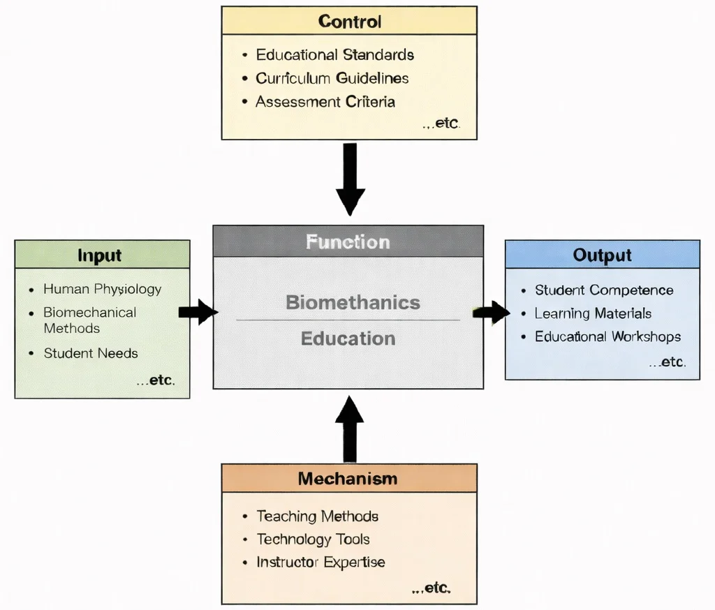
IDEF0 view of Biomechanics Education: physiology and biomechanical methods guided by standards and assessment, enabled by teaching and tools, producing student competence and learning resources.

Biomechanics uses physics and anatomy to understand how the body moves, absorbs forces, and avoids injury. This illustration portrays biomechanics as the science of motion and load in the human body. At the center, a semi-transparent runner is rendered with visible muscle fibers and emphasized joints, suggesting analysis of gait, posture, and joint mechanics. Around the figure, skeletal reference panels and data-style overlays indicate measurement and modelling—such as force distribution, impact, and alignment. On the left, orthopedic components such as hip and knee implants connect the study of movement to clinical applications, including rehabilitation and prosthetic or implant design. Overall, the image communicates how biomechanics combines anatomy, engineering, and data to improve performance, safety, and medical outcomes.
Biomedical Engineering – Knowledge Map
Biomedical Engineering – Overview
Situates biomechanical analysis within the wider effort to understand and support human function through engineering principles and integrative technological design.
Biomechanics (Current Module)
Examines how internal and external forces, kinematic movement, and material properties govern movement, structural stability, and injury mechanisms across biological systems.
Biomaterials
Determines how synthetic and natural materials respond mechanically to physiological stresses and strains when integrated into bone, joint, and soft tissue structures.
Tissue Engineering & Regenerative Medicine
Recreates specific biomechanical microenvironments and mechanical strain cues that guide cellular differentiation and restore fully functional tissue behavior.
Cardiovascular Engineering
Studies hemodynamics, fluid velocity vectors, and wall shear stress dynamics that govern blood circulation, vascular elasticity, and heart valve mechanics.
Neural Engineering
Links biomechanical movement with motor control pathways, examining how neural impulses translate into mechanical forces and coordinated muscle activation.
Medical Imaging
Captures volumetric 3D structural geometries and dynamic motion tracking data to visualize and quantify biomechanical loading in living subjects.
Biomedical Signal Processing
Processes electromyographic (EMG) muscle activity and sensor telemetry data to extract quantitative metrics on muscle fatigue and movement efficiency.
Bioinformatics
Provides mechanobiological and genomic insights that explain how cellular structures sense, transduce, and adapt to long-term mechanical loading at the molecular level.
Pharmaceutical Engineering
Considers how therapeutic compounds and targeted drug delivery systems influence tissue viscoelasticity, healing processes, and mechanical stress resilience.
Rehabilitation Engineering
Applies biomechanical principles to design assistive exoskeletons, custom orthotics, and adaptive mobility systems that restore independent movement.
Clinical Engineering
Ensures that motion capture systems, force plates, and biomechanical clinical diagnostic hardware operate safely, accurately, and in compliance with healthcare standards.
Core Concepts in Biomechanics
Kinematics
- Definition: The study of motion without considering the forces that cause it.
- Focus Areas:
- Displacement, velocity, and acceleration of body segments.
- Analysis of gait, joint angles, and body movements.
- Applications:
- Evaluating running and walking patterns to improve athletic performance or rehabilitate injuries.
Kinetics
- Definition: The study of forces and torques that cause motion.
- Focus Areas:
- Ground reaction forces, joint forces, and muscle forces.
- Interaction between internal forces such as muscle contractions and external forces such as gravity and friction.
- Applications:
- Designing orthopedic implants to withstand physical loads.
- Analyzing the impact of sports movements on joints to prevent injuries.
Tissue Mechanics
- Definition: The study of the mechanical behavior of biological tissues such as bones, muscles, tendons, and ligaments.
- Focus Areas:
- Stress-strain relationships of biological tissues.
- Material properties such as elasticity, plasticity, and viscoelasticity.
- Applications:
- Designing more durable and biocompatible prosthetics and implants.
Fluid Biomechanics
- Definition: Analysis of fluid flow within biological systems.
- Focus Areas:
- Blood flow in arteries and veins.
- Airflow in the respiratory system.
- Applications:
- Understanding cardiovascular diseases.
- Designing artificial heart valves and vascular grafts.
Neuromuscular Biomechanics
- Definition: The interaction between the nervous system and the musculoskeletal system to produce movement.
- Focus Areas:
- Muscle activation patterns.
- Coordination of movement.
- Applications:
- Rehabilitation robotics.
- Exoskeleton design for mobility support.
Applications of Biomechanics
Prosthetics and Orthotics
- Prosthetics:
- Designing artificial limbs that mimic natural movement.
- Incorporating lightweight and durable materials to improve comfort and function.
- Using robotics and AI to enhance control and mobility in prosthetic limbs.
- Orthotics:
- Creating supportive devices to correct or accommodate musculoskeletal deformities.
- Custom orthotic insoles to improve gait and reduce pain.
Orthopedics
- Implant Design:
- Developing joint replacements, such as hip, knee, and shoulder implants, that withstand biomechanical loads.
- Creating spinal implants and fixation devices.
- Bone and Joint Health:
- Studying the mechanical behavior of bones to prevent fractures and degenerative diseases.
- Optimizing surgical procedures such as ACL reconstruction using biomechanical data.
Sports Biomechanics
- Performance Enhancement:
- Analyzing athletes’ movements to improve technique and performance.
- Designing sport-specific equipment, such as running shoes or golf clubs, for better efficiency.
- Injury Prevention:
- Identifying harmful movement patterns to reduce the risk of injury.
- Developing protective gear to minimize impact forces.
Rehabilitation Engineering
- Assistive Devices:
- Designing exoskeletons and robotic devices to restore mobility in patients with neurological injuries.
- Developing smart wheelchairs and mobility aids.
- Therapy Optimization:
- Using motion analysis to guide physical therapy.
- Customizing rehabilitation programs based on biomechanical feedback.
Ergonomics and Workplace Safety
- Workplace Design:
- Optimizing workstation design to reduce repetitive strain injuries.
- Designing tools and equipment to align with human biomechanics.
- Manual Handling:
- Developing lifting techniques and supportive gear to prevent musculoskeletal injuries.
Biomedical Device Development
- Wearable Technology:
- Designing wearable sensors to monitor joint movement, posture, and muscle activity.
- Implantable Devices:
- Creating bioengineered implants that adapt to mechanical stress in the body.
Technologies in Biomechanics
Motion Capture Systems
- Function: Tracks and analyzes body movement in 3D.
- Applications: Sports performance analysis, rehabilitation, and gait analysis.
Force Plates and Pressure Sensors
- Function: Measures ground reaction forces and pressure distribution.
- Applications: Assessing balance, gait, and jump dynamics; studying injury risks in athletes.
Finite Element Analysis (FEA)
- Function: Simulates how biological structures respond to external forces.
- Applications: Designing orthopedic implants and prosthetics; evaluating mechanical strength of bones and tissues.
Electromyography (EMG)
- Function: Measures electrical activity in muscles.
- Applications: Assessing muscle activation patterns; diagnosing neuromuscular disorders.
Computational Modeling and Simulation
- Function: Creates digital models of biological systems for analysis.
- Applications: Simulating joint mechanics under different movement scenarios; predicting performance of medical devices.
Contemporary AI-Era Computational Paradigms in Biomechanics
During single-leg stance, an individual of body mass \(m = 70.0 \text{ kg}\) supports their entire body weight on one limb. The effective mass of the body excluding the stance leg is \(m_{\text{trunk}} = 56.0 \text{ kg}\), acting at a horizontal moment arm \(d_1 = 10.0 \text{ cm}\) (\(0.10 \text{ m}\)) medial to the hip joint rotation center. The gluteus medius abductor muscle complex inserts laterally with an effective moment arm \(d_2 = 5.0 \text{ cm}\) (\(0.05 \text{ m}\)), oriented at an angle \(\theta = 70.0^\circ\) relative to the horizontal. Calculate the required abductor muscle force \(F_M\) for static moment equilibrium, and evaluate the resultant hip Joint Reaction Force (\(\text{JRF}\)) magnitude:
$$\sum M_{\text{hip}} = 0 \Rightarrow W_{\text{trunk}} \cdot d_1 - F_M \cdot d_2 = 0$$Step 1: Compute trunk gravitational body weight force \(W_{\text{trunk}}\) (\(g = 9.81 \text{ m/s}^2\)):
$$W_{\text{trunk}} = 56.0 \text{ kg} \times 9.81 \text{ m/s}^2 = \mathbf{549.36 \text{ N}}$$Step 2: Solve for abductor muscle tensile force \(F_M\) about the hip fulcrum:
$$F_M = \frac{W_{\text{trunk}} \cdot d_1}{d_2} = \frac{549.36 \text{ N} \times 0.10 \text{ m}}{0.05 \text{ m}} = \mathbf{1,098.72 \text{ N}}$$Step 3: Resolve forces along horizontal (\(x\)) and vertical (\(y\)) axes to determine \(\text{JRF}\):
$$\sum F_x = 0 \Rightarrow JRF_x = F_M \cos(70^\circ) = 1,098.72 \times 0.34202 = \mathbf{375.78 \text{ N}}$$ $$\sum F_y = 0 \Rightarrow JRF_y = W_{\text{trunk}} + F_M \sin(70^\circ) = 549.36 + (1,098.72 \times 0.93969) = 549.36 + 1,032.46 = \mathbf{1,581.82 \text{ N}}$$ $$JRF = \sqrt{(JRF_x)^2 + (JRF_y)^2} = \sqrt{(375.78)^2 + (1,581.82)^2} = \sqrt{141,210.6 + 2,502,154.5} = \mathbf{1,625.96 \text{ N}}$$Biomechanical Interpretation: Total compressive joint reaction force on the femoral head reaches \(1,626.0 \text{ N}\) (\(\approx 2.37 \times\) total body weight) during static single-leg balance. This dramatic mechanical amplification highlights why maintaining abductor muscle strength is vital for minimizing osteoarthritis wear in prosthetic hip replacements.
Engineering Trade-offs in Biomechanics
| Biomechanical Design Trade-off | Primary Engineering Benefit | Systemic Penalty / Risk | Quantitative Design Metric |
|---|---|---|---|
| Titanium Alloy (Ti-6Al-4V) vs. Cobalt-Chromium (CoCr) Femoral Stems | Lower Young's modulus (\(E \approx 110 \text{ GPa}\)) closer to cortical bone (\(E \approx 18 \text{ GPa}\)), reducing stress shielding bone loss. | Lower abrasive wear resistance compared to CoCr when functioning as direct articulating bearing surfaces. | Elastic Modulus Match: Ti-6Al-4V (\(110 \text{ GPa}\)); CoCr (\(210\text{--}240 \text{ GPa}\)). |
| Rigid Carbon-Fiber AFO vs. Articulated Dynamic Ankle Orthosis | Maximizes energy storage and return during push-off; maximum coronal and sagittal plane stability. | Eliminates normal ankle joint range of motion, inducing compensatory knee hyperextension during terminal stance. | Stiffness Coefficient: Rigid AFO (\(K_{\text{rot}} \ge 3.0 \text{ N}\cdot\text{m/deg}\)). |
| Porous Trabecular Ingrowth Surfaces vs. PMMA Bone Cement Fixation | Biological osseointegration creates permanent living bone-implant interface, preventing late cement debonding. | Requires strict initial micromotion limits (\(< 50 \text{ \mu m}\)) during immediate post-operative period to prevent fibrous tissue encapsulation. | Interfacial Shear Strength: Biological Osseointegration (\(\ge 15 \text{ MPa}\)). |
| Powered Robotic Knee-Ankle Prosthesis vs. Passive Elastic Blade | Actively injects positive mechanical work during toe-off, normalizing metabolic oxygen consumption during uphill gait. | Substantial mass penalty (\(>4.0 \text{ kg}\)), limited battery life (\(8\text{--}12 \text{ hours}\)), and acoustic actuator noise. | Metabolic Cost of Transport: Powered Prosthesis saves \(15\text{--}25\%\) net metabolic energy. |
According to Wolff's Law of bone remodeling, bone tissue resorbs in regions where functional mechanical stress drops below homeostatic remodeling thresholds. In a composite femoral structure composed of cortical bone (cross-sectional area \(A_b = 350.0 \text{ mm}^2\), Young's modulus \(E_b = 18.0 \text{ GPa}\)) and an intramedullary stem (\(A_s = 150.0 \text{ mm}^2\)), calculate the fraction of an axial compressive gait load \(P = 2,500.0 \text{ N}\) transferred through the stem if the stem is manufactured from (a) Titanium Alloy (\(E_s = 110.0 \text{ GPa}\)) versus (b) Stainless Steel (\(E_s = 200.0 \text{ GPa}\)):
$$\text{Axial Rigidity} = (EA)_{\text{total}} = E_b A_b + E_s A_s$$ $$\text{Load Fraction Carried by Stem} = \frac{E_s A_s}{(EA)_{\text{total}}} = \frac{E_s A_s}{E_b A_b + E_s A_s}$$Step 1: Compute bone axial stiffness \(E_b A_b\):
$$E_b A_b = 18.0 \text{ GPa} \times 350.0 \text{ mm}^2 = \mathbf{6,300.0 \text{ kN}}$$Step 2: Case A - Titanium Stem (\(E_s = 110.0 \text{ GPa}\)):
$$E_{s,\text{Ti}} A_s = 110.0 \text{ GPa} \times 150.0 \text{ mm}^2 = 16,500.0 \text{ kN}$$ $$\text{Fraction}_{\text{Ti}} = \frac{16,500.0}{6,300.0 + 16,500.0} = \frac{16,500.0}{22,800.0} = \mathbf{72.37\%} \quad (\text{Bone carries } 27.63\%)$$Step 3: Case B - Stainless Steel Stem (\(E_s = 200.0 \text{ GPa}\)):
$$E_{s,\text{Steel}} A_s = 200.0 \text{ GPa} \times 150.0 \text{ mm}^2 = 30,000.0 \text{ kN}$$ $$\text{Fraction}_{\text{Steel}} = \frac{30,000.0}{6,300.0 + 30,000.0} = \frac{30,000.0}{36,300.0} = \mathbf{82.64\%} \quad (\text{Bone carries } 17.36\%)$$Design Assessment: The stiffer stainless steel implant absorbs 82.6% of the gait load, leaving the host cortical bone under-stimulated (carrying only 17.4% of axial force). This triggers extensive proximal osteopenia and implant loosening over decadal timeframes, demonstrating why lower-modulus porous titanium alloys are preferred.
Interactive Biomechanical Gait & Joint Force Simulator
Ground Reaction Force (GRF) Stance Curve
Joint Reaction Force (Patellofemoral JRF)
Interactive runtime environment: https://prep4uni.online/stem/physical-technologies/biomedical-engineering/biomechanics/
Challenges in Biomechanics
Complexity of Biological Systems
- Inherent Variability: Each human body differs significantly in size, muscle strength, bone density, and joint mobility, making it difficult to create standardized biomechanical models. Age, sex, ethnicity, and lifestyle factors further complicate generalization.
- Tissue Behavior: Biological tissues are anisotropic, viscoelastic, and non-linear in their mechanical behavior. This makes modeling them far more difficult than simple engineering materials.
- Dynamic Interactions: The interplay between muscles, bones, tendons, and neural control systems varies continuously with time and activity, introducing additional layers of complexity.
Integration of Multidisciplinary Knowledge
- Cross-Disciplinary Expertise: Effective biomechanical analysis requires knowledge in anatomy, physiology, mechanical engineering, materials science, computer science, and clinical medicine. The breadth of knowledge required creates a high barrier to entry for researchers and practitioners.
- Communication Barriers: Different disciplines often use different terminologies, data standards, and software tools, making collaborative work challenging.
- Educational Gaps: Most university programs do not fully integrate this interdisciplinary knowledge into a single curriculum, resulting in professionals with gaps in one or more key domains.
Data Accuracy and Validation
- Measurement Challenges: Accurate real-time data on internal body mechanics is difficult to acquire non-invasively. Techniques like motion capture, force plates, and imaging have limitations in resolution and fidelity.
- Model Validation: Validating simulations against in vivo conditions is difficult due to ethical constraints and technological limits in tracking internal structures like ligaments or cartilage under load.
- Environmental Variation: Real-world conditions such as uneven terrain, fatigue, or disease progression introduce variability that cannot be fully replicated in laboratory settings.
Ethical Considerations
- Human Subject Research: Biomechanical testing on living subjects must comply with strict ethical standards. The need to avoid harm limits invasive measurements and testing, especially for vulnerable populations such as children or the elderly.
- Animal Testing: While often necessary, animal models do not always accurately reflect human biomechanics, and their use raises ethical concerns in research communities.
- AI and Bias: The growing use of AI in biomechanical prediction, such as gait analysis or injury risk estimation, raises concerns about algorithmic bias and equity in treatment outcomes.
Customization of Solutions
- Personalization Needs: Effective prosthetic and orthotic solutions must be custom-designed for individual anatomy and activity level, requiring detailed imaging and patient data.
- Manufacturing Limits: Additive manufacturing has revolutionized customization, but still faces issues with material biocompatibility, mechanical integrity, and regulatory approval.
- Cost and Accessibility: Custom devices are expensive and often unavailable in resource-limited settings, raising concerns about global health equity.
Computational Limitations and Simulation Complexity
- High Computational Demand: Accurate simulations, particularly those involving finite element models of human joints or muscles, are computationally expensive and time-consuming.
- Real-Time Analysis: For applications in wearable technologies or surgical robotics, biomechanical models must compute in real time, a capability still under development.
- Data Fusion: Integrating data from sensors such as EMG, IMU, and ultrasound into a unified model without loss of accuracy or latency is an ongoing challenge.
Translational Gaps Between Research and Clinical Practice
- Limited Adoption: Many advanced biomechanical tools remain underused in clinical settings due to complexity, lack of training, or regulatory barriers.
- Workflow Integration: Integrating biomechanical data into electronic health records and decision-support systems is still in its infancy.
- Outcome Measurement: There is often a lack of standardized metrics to evaluate the effectiveness of biomechanical interventions in real-world healthcare environments.
Conclusion
Future Trends in Biomechanics
Smart Prosthetics and Wearables
3D Printing of Customized Implants
Bioengineered Tissues and Organs
Virtual Reality and Augmented Reality in Biomechanical Training
Machine Learning and Big Data Analytics
Digital Twins and Biomechanical Simulation
Exoskeletons and Assistive Robotics
Neurobiomechanics and Brain-Body Interfaces
Biomechanics in Space Exploration and Aging
Sustainable and Bioinspired Materials
Why Study Biomechanics
Biomechanics: Conclusion
Impact on Healthcare and Prosthetics
Revolutionizing Rehabilitation and Physical Therapy
Performance Optimization in Sports and Exercise Science
Applications in Ergonomics and Workplace Safety
Driving Innovation in Robotics and Human-Machine Interfaces
Contributions to Aging and Fall Prevention
Educational and Research Significance
Environmental and Global Health Applications
Future Outlook: Boundless Potential
References
- NIH – Advances in Biomechanical Research and Applications
- World Health Organization – Assistive Technology
Frequently Asked Questions on Biomechanics
Why is biomechanics so central to modern biomedical engineering?
Biomechanics sits at the meeting point of physics, engineering, and anatomy. By treating the body as a system of forces, motions, and materials, it helps us understand why joints wear out, how injuries occur, and what makes movement efficient or painful. This knowledge is essential for designing implants, prosthetics, rehabilitation devices, and surgical techniques that work with the body instead of against it.
Is biomechanics only about sports and elite athletes?
Elite sport provides striking examples, but biomechanics is just as relevant to everyday activities such as walking, lifting, or climbing stairs. The same principles apply when designing safer workplaces, fall-prevention strategies for older adults, or better wheelchairs and walking aids. In that sense, biomechanics is about movement for everyone, not only for top performers.
How mathematical is biomechanics as a subject?
Biomechanics uses the language of mechanics: forces, moments, equilibrium, stress, and strain. Students do not have to be mathematicians, but comfort with basic algebra, vectors, and Newton’s laws is helpful. At university level, the subject gradually introduces more formal modelling, such as differential equations or finite element analysis, but always with the goal of explaining real movement and real devices.
What is the difference between musculoskeletal biomechanics and biofluid mechanics?
Musculoskeletal biomechanics focuses on bones, muscles, tendons, ligaments, and joints, asking how they generate and transmit forces during movement. Biofluid mechanics examines the flow of biological fluids such as blood, cerebrospinal fluid, or air in the lungs. Both areas rely on the same physical principles, but one treats the body as a system of levers and supports, while the other treats it as a system of channels and flows.
How does biomechanics influence the design of prosthetic limbs?
In prosthetic design, biomechanics provides target values for joint angles, step lengths, and ground reaction forces that resemble natural gait. Engineers use these data to choose appropriate materials, align components, and design control systems so that the prosthesis feels stable, efficient, and comfortable. Biomechanics also helps evaluate new designs by comparing how closely they reproduce healthy movement patterns.
Where does biomechanics connect with rehabilitation and clinical practice?
Clinicians use biomechanical measurements—such as gait analysis, pressure mapping, or motion capture—to understand why a patient moves in a particular way. Engineers then translate these findings into supports, exercises, or devices that reduce harmful loading and strengthen useful movement patterns. In this partnership, biomechanics acts as the common framework that links clinical observations to engineering solutions.
What should a student look out for when first studying biomechanics?
It helps to constantly connect equations back to simple questions: Where is this force coming from? Which structure is carrying it? How might this change if the person were older, injured, or running instead of walking? Keeping that link between mathematics and the moving body makes biomechanics both more memorable and more useful for future study and professional work.
Interactive Concept Review Exercises
Review Question 1: How does the analysis of gait biomechanics contribute to the design of lower-limb prosthetics?
Review Question 2: Why are biological soft tissues characterized as viscoelastic?
Review Question 3: How does finite element analysis (FEA) assist in orthopedic implant design?
End-of-Page Comprehensive Practice Module
Section 1: Foundational Review Questions
1. What is biomechanics, and what kinds of questions does it try to answer?
2. What are the main subfields of biomechanics commonly discussed in biomedical engineering?
3. What does musculoskeletal biomechanics investigate, and why is it important for device design?
4. How is cardiovascular biomechanics used in the development of cardiovascular devices?
5. What is cellular biomechanics, and how does it support areas like tissue engineering and cancer research?
6. What does biofluid mechanics study, and which medical technologies rely on it?
7. How do biomechanical principles guide the design of prosthetic limbs and rehabilitation devices?
8. What types of innovations in orthopedic implants have emerged from biomechanical research?
9. How do biomechanics and finite element analysis work together in modeling tissues and devices?
10. In what ways does biomechanics contribute to rehabilitation, injury prevention, and performance optimization?
Section 2: Analytical & Scenario-Based Thought Questions
1. Explain how the lever arm ratio between the Achilles tendon force and ground reaction force affects calf muscle load during human jumping.
2. Describe the mechanotransduction pathway through which bone osteocytes respond to mechanical loading under Wolff's Law.
3. Why does arterial wall shear stress (\(\tau_w\)) drop in dilated aneurysmal regions, and what are the biological consequences?
4. Compare the stress-strain behavior of collagen fibers versus elastin fibers in arterial tissue.
5. How does viscoelastic creep differ from stress relaxation in ligament biomechanics?
6. Analyze the biomechanical rationale for placing a cane in the hand opposite to an injured or arthritic hip joint.
7. What limits the accuracy of surface electromyography (sEMG) in driving real-time biomechanical inverse dynamics models?
Section 3: Quantitative Engineering Calculations
1. Single-Leg Stance Hip Abductor Muscle Force Calculation
Problem: During single-leg stance, a person of body mass \(m = 70.0 \text{ kg}\) supports their body weight. The center of mass of the body excluding the stance leg (mass \(m_{\text{trunk}} = 56.0 \text{ kg}\)) acts at a distance \(d_1 = 10.0 \text{ cm}\) (\(0.10 \text{ m}\)) from the hip joint center. The hip abductor muscle acts with a moment arm \(d_2 = 5.0 \text{ cm}\) (\(0.05 \text{ m}\)). Calculate the required abductor muscle force (\(F_M\)) in Newtons for static equilibrium (\(g = 9.81 \text{ m/s}^2\)).
Answer:
Step 1: Calculate body weight force (\(W\)) acting on stance hip:
\(W = 56.0 \text{ kg} \times 9.81 \text{ m/s}^2 = 549.36 \text{ N}\)
Step 2: Set up torque equilibrium around hip joint center (\(\sum M = 0\)):
\(\text{Torque from Body Weight} = W \times d_1 = 549.36 \text{ N} \times 0.10 \text{ m} = 54.936 \text{ N}\cdot\text{m}\)
\(\text{Torque from Abductor Muscle} = F_M \times d_2 = F_M \times 0.05 \text{ m}\)
Step 3: Solve for muscle force (\(F_M\)):
\(F_M \times 0.05 \text{ m} = 54.936 \text{ N}\cdot\text{m} \Rightarrow F_M = \frac{54.936}{0.05} = \mathbf{1,098.72 \text{ N}}\)
The required hip abductor muscle force is 1,098.72 N.
2. Articular Cartilage Unconfined Compression & Deformation
Problem: An articular cartilage tissue cylindrical plug (diameter \(d = 8.0 \text{ mm}\), length \(L_0 = 3.0 \text{ mm}\)) is subjected to an unconfined compressive test load \(F = 25.0 \text{ N}\). Calculate compressive stress (\(\sigma\)) in \(\text{MPa}\). If the equilibrium compressive modulus \(H_A = 0.80 \text{ MPa}\), calculate the total length decrease (\(\Delta L\)) in \(\text{mm}\).
Answer:
Step 1: Calculate cross-sectional area (\(A\)):
\(r = 4.0 \text{ mm} = 0.004 \text{ m}\)
\(A = \pi r^2 = \pi \times (0.004 \text{ m})^2 = 5.0265 \times 10^{-5} \text{ m}^2 = 50.265 \text{ mm}^2\)
Step 2: Calculate compressive stress (\(\sigma\)):
\(\sigma = \frac{F}{A} = \frac{25.0 \text{ N}}{50.265 \text{ mm}^2} = \mathbf{0.497 \text{ MPa}}\)
Step 3: Calculate compressive strain (\(\varepsilon = \sigma / H_A\)):
\(\varepsilon = \frac{0.497 \text{ MPa}}{0.80 \text{ MPa}} = 0.62125\)
Step 4: Calculate length deformation (\(\Delta L = \varepsilon \times L_0\)):
\(\Delta L = 0.62125 \times 3.0 \text{ mm} = \mathbf{1.864 \text{ mm}}\)
The cartilage experiences a stress of 0.497 MPa resulting in a deformation of 1.864 mm.
3. Femoral Artery Wall Shear Stress Calculation
Problem: Blood with dynamic viscosity \(\eta = 0.0035 \text{ Pa}\cdot\text{s}\) flows through a laminar femoral artery of inner radius \(r = 4.0 \text{ mm}\) (\(0.004 \text{ m}\)) at a volumetric flow rate \(Q = 350.0 \text{ mL/min}\). Convert \(Q\) to \(\text{m}^3/\text{s}\) and calculate the wall shear stress (\(\tau_w\)) in Pascals.
Answer:
Step 1: Convert flow rate (\(Q\)) to \(\text{m}^3/\text{s}\):
\(Q = \frac{350.0 \times 10^{-6} \text{ m}^3}{60 \text{ s}} = 5.8333 \times 10^{-6} \text{ m}^3/\text{s}\)
Step 2: Apply Poiseuille wall shear stress formula (\(\tau_w = \frac{4 \eta Q}{\pi r^3}\)):
\(r^3 = (0.004 \text{ m})^3 = 6.40 \times 10^{-8} \text{ m}^3\)
\(\text{Numerator} = 4 \times 0.0035 \text{ Pa}\cdot\text{s} \times 5.8333 \times 10^{-6} \text{ m}^3/\text{s} = 8.1666 \times 10^{-8} \text{ N}\cdot\text{m}\)
\(\text{Denominator} = \pi \times 6.40 \times 10^{-8} \text{ m}^3 = 2.0106 \times 10^{-7} \text{ m}^3\)
\(\tau_w = \frac{8.1666 \times 10^{-8}}{2.0106 \times 10^{-7}} = \mathbf{0.406 \text{ Pa}}\)
The femoral arterial wall shear stress is 0.406 Pa.
4. Knee Ligament Viscoelastic Stress Relaxation
Problem: A knee joint ligament undergoes a constant elongation test. Its stress relaxation follows the Maxwell viscoelastic model: \(\sigma(t) = \sigma_0 \cdot \exp(-t / \tau)\). If initial stress \(\sigma_0 = 12.0 \text{ MPa}\) and the relaxation time constant \(\tau = 15.0 \text{ s}\), calculate the stress in the ligament at \(t = 30.0 \text{ s}\).
Answer:
Step 1: Compute exponent value (\(-t / \tau\)):
\(\frac{-t}{\tau} = \frac{-30.0 \text{ s}}{15.0 \text{ s}} = -2.0\)
Step 2: Evaluate \(\exp(-2.0)\):
\(\exp(-2.0) \approx 0.135335\)
Step 3: Calculate remaining stress (\(\sigma(30)\)):
\(\sigma(30) = 12.0 \text{ MPa} \times 0.135335 = \mathbf{1.624 \text{ MPa}}\)
The remaining stress in the ligament at 30 seconds is 1.624 MPa.
5. Ground Reaction Force Vertical Impulse Calculation
Problem: A runner's foot strikes a force plate during gait analysis. The vertical ground reaction force \(F_z(t)\) follows a half-sine pulse \(F_z(t) = F_{\text{peak}} \cdot \sin(\pi t / T)\) over contact time \(T = 0.20 \text{ s}\). If \(F_{\text{peak}} = 2,100.0 \text{ N}\), calculate the vertical impulse (\(J_z = \int_0^T F_z \, dt\)) in \(\text{N}\cdot\text{s}\).
Answer:
Step 1: Integrate the sine pulse function from \(t = 0\) to \(t = T\):
\(\int_0^T \sin\left(\frac{\pi t}{T}\right) dt = \left[ -\frac{T}{\pi} \cos\left(\frac{\pi t}{T}\right) \right]_0^T = \frac{T}{\pi} [-\cos(\pi) - (-\cos(0))] = \frac{2T}{\pi}\)
Step 2: Substitute values into impulse equation (\(J_z = F_{\text{peak}} \times \frac{2T}{\pi}\)):
\(J_z = 2,100.0 \text{ N} \times \left(\frac{2 \times 0.20 \text{ s}}{\pi}\right) = 2,100.0 \times \left(\frac{0.40}{3.14159}\right) = 2,100.0 \times 0.127324 = \mathbf{267.38 \text{ N}\cdot\text{s}}\)
The total vertical ground reaction impulse is 267.38 N·s.
6. Lumbar L5/S1 Spinal Disc Bending Moment in Lifting
Problem: Calculate the sagittal bending moment (\(M\)) generated at the L5/S1 spinal disc when a worker lifts a box of mass \(m = 20.0 \text{ kg}\) held at a horizontal distance \(d = 0.45 \text{ m}\) anterior to the disc center. Assume trunk weight above L5/S1 is \(W_{\text{trunk}} = 350.0 \text{ N}\) acting at distance \(d_{\text{trunk}} = 0.25 \text{ m}\) (\(g = 9.81 \text{ m/s}^2\)).
Answer:
Step 1: Calculate box weight force (\(W_{\text{box}}\)):
\(W_{\text{box}} = 20.0 \text{ kg} \times 9.81 \text{ m/s}^2 = 196.20 \text{ N}\)
Step 2: Compute bending moment from box load (\(M_{\text{box}} = W_{\text{box}} \times d\)):
\(M_{\text{box}} = 196.20 \text{ N} \times 0.45 \text{ m} = 88.29 \text{ N}\cdot\text{m}\)
Step 3: Compute bending moment from upper trunk body mass (\(M_{\text{trunk}} = W_{\text{trunk}} \times d_{\text{trunk}}\)):
\(M_{\text{trunk}} = 350.0 \text{ N} \times 0.25 \text{ m} = 87.50 \text{ N}\cdot\text{m}\)
Step 4: Sum bending moments for total flexion torque (\(M_{\text{total}}\)):
\(M_{\text{total}} = 88.29 \text{ N}\cdot\text{m} + 87.50 \text{ N}\cdot\text{m} = \mathbf{175.79 \text{ N}\cdot\text{m}}\)
The total flexion moment at the L5/S1 spinal disc is 175.79 N·m.
7. Femoral Cortical Bone Polar Moment of Inertia & Torsional Stress
Problem: A femoral bone cortical shaft has an outer radius \(r_o = 14.0 \text{ mm}\) and inner marrow radius \(r_i = 8.0 \text{ mm}\). Calculate its polar moment of inertia (\(J\)) in \(\text{mm}^4\) and the maximum torsional shear stress (\(\tau_{\max}\)) when subjected to a twisting torque \(T = 60.0 \text{ N}\cdot\text{m}\).
Answer:
Step 1: Calculate Polar Moment of Inertia \(J = \frac{\pi}{2} (r_o^4 - r_i^4)\):
\(r_o^4 = (14.0)^4 = 38,416.0 \text{ mm}^4\)
\(r_i^4 = (8.0)^4 = 4,096.0 \text{ mm}^4\)
\(r_o^4 - r_i^4 = 34,320.0 \text{ mm}^4\)
\(J = \frac{\pi}{2} \times 34,320.0 = \mathbf{53,910.12 \text{ mm}^4}\)
Step 2: Convert twisting torque to \(\text{N}\cdot\text{mm}\):
\(T = 60.0 \text{ N}\cdot\text{m} = 60,000.0 \text{ N}\cdot\text{mm}\)
Step 3: Apply the elastic torsion formula (\(\tau_{\max} = \frac{T \cdot r_o}{J}\)):
\(\tau_{\max} = \frac{60,000.0 \text{ N}\cdot\text{mm} \times 14.0 \text{ mm}}{53,910.12 \text{ mm}^4} = \frac{840,000.0}{53,910.12} = \mathbf{15.58 \text{ MPa}}\)
The femoral shaft polar moment of inertia is 53,910.1 mm⁴ and maximum torsional shear stress is 15.58 MPa.