
- Kinematics & Geometric Mapping: Formulate coordinate frame transformations using Denavit-Hartenberg (D-H) 4×4 homogeneous matrices, analytical inverse kinematics, and workspace reach envelopes.
- Differential Motion & Statics: Derive the geometric Jacobian matrix, resolve joint velocities to Cartesian task rates, map wrench forces via virtual work, and identify boundary and interior singularities.
- Dynamic Equations of Motion: Formulate multi-link dynamics via the Lagrange-Euler energy method, evaluate mass-inertia matrices, centrifugal and Coriolis torque vectors, and calculate optimal actuator gear ratio matching.
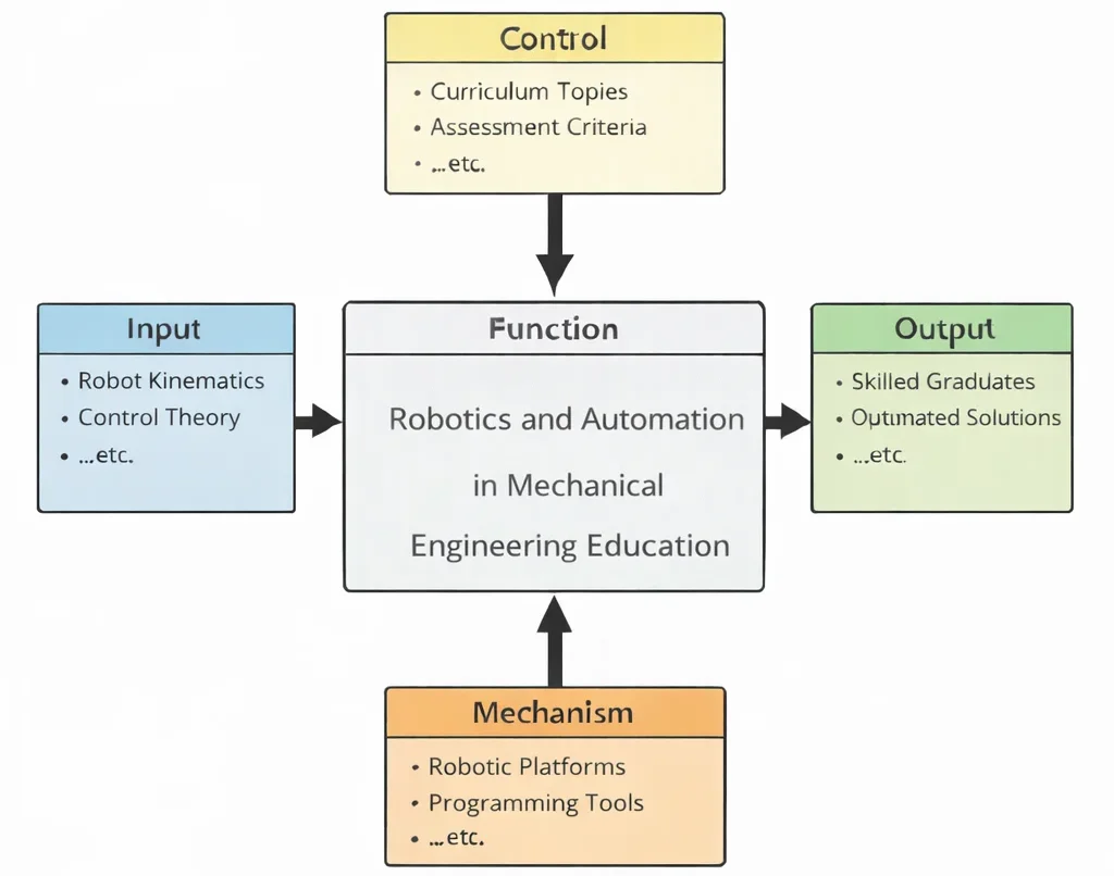
- Inputs (Left): Multi-link kinematic topologies, target tool-center-point (TCP) trajectories, payload mass envelopes, sensor telemetry, and dynamic environmental disturbance profiles.
- Controls (Top): Washington Accord/EUR-ACE quality criteria, ISO 10218-1/2 industrial robot safety mandates, ISO/TS 15066 collaborative robot thresholds, and cycle time limits.
- Mechanisms (Bottom): 6-axis articulated arms, harmonic drive gearboxes, absolute optical encoders, 6-axis wrist force-torque transducers, ROS2/MoveIt motion planners, and real-time EtherCAT fieldbuses.
- Outputs (Right): Certified collision-safe manipulator cells, optimized singularity-free toolpaths, validated dynamic load profiles, and industry-ready automation engineers.
Mechanical & Robotics Engineering Curriculum Cluster
Select any foundational pillar below to explore related modules across the PREP4UNI.ONLINE Mechanical Engineering series:
Mechanical Engineering
Provides kinematic synthesis, static force balances, actuator thermal ratings, and dynamic stability for automated systems.
Automotive Engineering
Deploys SLAM trajectory planning on autonomous industrial mobile carts and integrates drive-by-wire electric steering.
Biomechanical Engineering
Translates human hand tremor cancellation algorithms to laparoscopic surgical telemanipulators and powered gait orthotics.
Control Systems in Mechanical Engineering
Executes digital computed-torque control, Kalman state estimation, and dynamic impedance feedback for robotic touch.
Fluid Mechanics and Hydraulics
Drives high-torque hydraulic actuators on heavy construction manipulators and operates pneumatic vacuum suction cups.
Manufacturing and Production Engineering
Orchestrates robotic CNC tendering, synchronized multi-arm automotive spot welding lines, and automated packaging cells.
Mechanical Design and CAD
Designs 6-DOF hollow arm castings to house internal wiring, gearboxes, and custom payload end-effector mounts.
Nanotechnology and Advanced Materials
Equips grippers with piezoresistive graphene pressure sensors and integrates shape memory alloy micro-actuators.
Robotics and Automation in Mechanical Engineering
Forward and inverse kinematics, Denavit-Hartenberg frames, path trajectory planning, dynamic torques, and automation.
Solid Mechanics: Stress, Strain & Structural Analysis
Calculates link deflection and torsional shaft windup during emergency high-inertia stops to maintain tool positional repeatability.
Thermodynamics and Heat Transfer
Dissipates continuous copper coil Joule heating in compact robot joints to prevent thermal demagnetization and stall.
Vibrations and Acoustics
Applies input shaping and notch filtering to eliminate end-effector residual oscillations during high-speed pick maneuvers.

Deep Technical Foundations: Analytical Kinematics & Multi-Body Manipulator Dynamics
Robotic manipulation bridges spatial geometry with dynamic balance. Achieving millimeter-level tracking accuracy under rapid acceleration requires modeling kinematic frame chains, resolving Jacobian singularities, and formulating multi-link equations of motion.
1. Forward Kinematics: The Denavit-Hartenberg (D-H) Formulation
Spatial relationships between adjacent coordinate frames (from link i−1 to link i) are established by four standard D-H parameters: link length ai−1, link twist αi−1, link offset di, and joint angle θi. The resulting homogeneous transformation matrix i−1Ti is expressed as:
$${}^{i-1}\mathbf{T}_i = \begin{bmatrix} \cos\theta_i & -\sin\theta_i\cos\alpha_{i-1} & \sin\theta_i\sin\alpha_{i-1} & a_{i-1}\cos\theta_i \\ \sin\theta_i & \cos\theta_i\cos\alpha_{i-1} & -\cos\theta_i\sin\alpha_{i-1} & a_{i-1}\sin\theta_i \\ 0 & \sin\alpha_{i-1} & \cos\alpha_{i-1} & d_i \\ 0 & 0 & 0 & 1 \end{bmatrix}$$Compounding individual link transformations from base frame (0) to end-effector tool-center-point (n) establishes the total forward kinematic map:
$${}^0\mathbf{T}_n = {}^0\mathbf{T}_1 \cdot {}^1\mathbf{T}_2 \cdot {}^2\mathbf{T}_3 \dots {}^{n-1}\mathbf{T}_n = \begin{bmatrix} \mathbf{R}_{3\times 3} & \mathbf{P}_{3\times 1} \\ \mathbf{0}_{1\times 3} & 1 \end{bmatrix}$$2. Differential Kinematics, Jacobian Matrix & Singularity Analysis
The geometric Jacobian matrix J(q) maps joint velocity vectors q̇ to Cartesian end-effector linear velocity v and angular velocity ω:
$$\mathbf{\dot{x}} = \begin{bmatrix} \mathbf{v} \\ \boldsymbol{\omega} \end{bmatrix} = \mathbf{J}(\mathbf{q}) \mathbf{\dot{q}} = \begin{bmatrix} \mathbf{J}_v(\mathbf{q}) \\ \mathbf{J}_\omega(\mathbf{q}) \end{bmatrix} \mathbf{\dot{q}}$$By the principle of virtual work, the transpose of the Jacobian matrix maps external Cartesian contact wrenches (forces and moments) Fext to required joint holding torques τ:
$$\boldsymbol{\tau} = \mathbf{J}^T(\mathbf{q}) \mathbf{F}_{\text{ext}}$$Kinematic singularities occur when the Jacobian matrix loses rank (det(J) = 0 for square Jacobians). At singular configurations, the manipulator loses one or more degrees of freedom, and inverse kinematic velocity solutions command infinite joint rates (Δq̇ → ∞).
3. Multi-Body Manipulator Dynamics: The Lagrange-Euler Formulation
The closed-form equations of motion for an n-link articulated manipulator operating under gravitational and inertial forces are derived via the Lagrangian L = K − P:
$$\mathbf{M}(\mathbf{q})\mathbf{\ddot{q}} + \mathbf{C}(\mathbf{q},\mathbf{\dot{q}})\mathbf{\dot{q}} + \mathbf{G}(\mathbf{q}) = \boldsymbol{\tau}$$where M(q) is the symmetric, positive-definite n×n mass-inertia matrix, C(q, q̇)q̇ is the n×1 vector of centrifugal and Coriolis torques, G(q) is the n×1 gravitational torque vector, and τ is the n×1 vector of generalized joint actuator torques.
Contemporary Computational Paradigms in Robotics & Automation
Modern industrial robotics has moved from rigid, pre-taught position playback to dynamic perception, physics-based simulation, and cloud-coordinated execution:
Physics-Informed Neural Networks for Dynamic Compensation
PINNs combine multi-body rigid dynamics with real-time drive current telemetry to estimate complex joint friction (Stribeck curve, viscous damping, and cable hysteresis). Feedforward neural networks cancel non-linear friction disturbances in real time, improving trajectory tracking precision by over 80%.
Model Predictive Trajectory Planning (NMPC)
Non-linear Model Predictive Control solves real-time Quadratic Programming (QP) optimization problems over a moving time horizon. NMPC plans time-optimal, collision-free Cartesian trajectories while strictly enforcing joint torque limits, motor voltage boundaries, and ISO 15066 collaborative speed thresholds.
Digital Twins & Hardware-in-the-Loop Simulation
Virtual commissioning environments (NVIDIA Isaac Sim, Gazebo) connect industrial PLCs and robot controllers over deterministic fieldbuses (EtherCAT, PROFINET). Complete factory assembly cells are tested, collision-checked, and cycle-time optimized in software before physical hardware installation.
Systems Engineering Trade-off Matrix
Designing robotic manipulation cells requires balancing structural rigidity, payload capacity, trajectory velocity, and collision safety:
| Robotic Architecture / Design Choice | Primary Engineering Advantage | Bottlenecks & Failure Modes | Mitigation & Control Strategy |
|---|---|---|---|
| High Gear Ratio Reduction (N > 100:1) | Amplifies joint motor torque; matches high-inertia mechanical links; enables compact electric motor packaging. | Reflects high mechanical friction and torsional compliance; magnifies gear backlash; introduces flex-spline hysteresis in harmonic drives. | Implement dual-encoder feedback (measuring motor shaft and joint output directly); utilize zero-backlash cycloidal speed reducers. |
| Direct-Drive Arm Architecture (N = 1:1) | Eliminates mechanical gear backlash and transmission friction; provides high dynamic bandwidth and backdrivability. | Requires large, heavy high-torque torque motors; low mechanical advantage causes high motor current draw and thermal heat dissipation. | Deploy water-cooled frameless torque motors; optimize link structural mass using topological carbon fiber composite casting. |
| Collaborative Robot (Cobot) Compliance | Enables safe fenceless human-robot collaboration; compliant joint torque sensors detect unintended collisions instantly. | Restricted payload capacity (< 15 kg); low maximum Cartesian speed (≤ 250 mm/s per ISO 10218) limits high-volume throughput. | Implement multi-zone safety LiDAR scanners: run at high speed when humans are absent, transitioning dynamically to safe mode upon approach. |
| Parallel Delta Robot Topology | Stationary base-mounted actuators reduce moving mass to near zero; delivers extreme accelerations (> 15g) in pick-and-place. | Severely restricted, shallow cylindrical workspace envelope; complex multi-loop inverse kinematics with numerous singular zones. | Deploy analytical algebraic singularity mapping; constrain pick-and-place motions strictly within central dextrous workspace boundaries. |
Cross-Sector Industrial Case Studies
Automotive BiW Resistance Spot Welding
Automotive Body-in-White (BiW) lines utilize heavy articulated 6-axis robots carrying 150-kg servo-electric weld guns. Trajectory controllers run model-based vibration suppression filters, enabling 2000 spot welds per vehicle with positioning repeatability within ±0.05 mm.
Semiconductor Wafer Vacuum Handlers
SCARA-type atmospheric and high-vacuum robotic transfer arms transport 300-mm silicon wafers between photolithography vacuum chambers. Direct-drive magnetically levitated joints eliminate lubricants, preventing particulate contamination in ISO Class 1 cleanrooms.
Aerospace Robotic Drilling & Fastening
Drilling fastener holes in titanium-composite aircraft fuselages requires 3 kN of normal clamping force. Robotic end-effectors incorporate pressure-foot load cells and secondary laser vision trackers, compensating for structural arm deflection in real time to maintain hole perpendicularity within 0.5 degrees.
Warehouse Autonomous Mobile Robots (AMRs)
Logistics fulfillment centers deploy fleets of differential-drive AMRs. Sensor-fusion algorithms combine 2D LiDAR simultaneous localization and mapping (SLAM) with wheel odometry and 3D depth cameras, moving 1.5-ton pallet racks along dynamic obstacle-free paths.
Interactive Simulation: 2-DOF Robotic Arm Kinematics & Reach Engine
Evaluate real-time forward kinematics, coordinate transformations, and reach boundaries for a two-link planar robotic manipulator using our verified zero-crash canvas architecture.
Interactive 2-DOF Robotic Arm Kinematics Simulator
STATUS: ACTIVE SOLVERSimulates planar forward kinematics for a two-link articulated arm (L1 = 1.2 m, L2 = 0.8 m). Adjust joint rotation angles to observe spatial end-effector coordinate positioning and workspace boundary reach.
Frequently Asked Questions: Industrial Robotics & Autonomous Systems
1. How do forward kinematics and inverse kinematics differ in complexity?
2. What is a robot kinematic singularity, and how do controllers avoid it?
3. Why is inertia matching critical in selecting robot actuator gear ratios?
4. What safety standards govern collaborative human-robot interaction (Cobots)?
5. How does the Jacobian transpose relate joint torques to end-effector contact forces?
6. What causes gear backlash in articulated robot joints, and how is it mitigated?
7. What is the fundamental difference between SCARA and Delta robot architectures?
8. How do industrial robots communicate over real-time deterministic fieldbuses?
Student Practice & Accreditation Assessment Modules
Section 1: Interactive Knowledge Self-Assessment
Q1: Formulate how cumulative positioning errors propagate along open serial kinematic chains.
Q2: Differentiate between repeatability and absolute accuracy in industrial manipulators.
- Repeatability: The ability of a manipulator to return to the exact same taught coordinate position under repeated cycles (typically ±0.02 mm in modern industrial arms).
- Absolute Accuracy: The ability of a robot to move to a mathematically programmed Cartesian coordinate without prior physical teaching (often ±0.5 to 2.0 mm due to link compliance, thermal expansion, and kinematic parameter manufacturing variances).
Q3: Why do industrial robots experience wrist singularities, and how are they identified?
Q4: How does dynamic operational space impedance control differ from pure position control?
Q5: Why is input shaping vibration control applied to flexible robotic manipulators?
Q6: What causes centrifugal and Coriolis torque coupling in multi-axis robotic arms?
Q7: Differentiate between LiDAR-based SLAM and visual SLAM for Autonomous Mobile Robots (AMRs).
Q8: Formulate why joint torque sensors enable fenceless collaborative operation.
Section 2: Analytical & Scenario-Based Case Studies
Scenario: A 6-axis articulated robot applying adhesive sealant along a car windshield frame produced uneven, discontinuous sealant beads and tripped axis overspeed alarms at the upper corner radius.
Engineering Evaluation:
1. Kinematic Alignment: Trajectory planning commanded the tool to maintain a constant normal angle while traversing across the roofline. At the upper corner, Joint 5 passed through zero degrees (θ5 = 0°), aligning Joint 4 and Joint 6 axes.
2. Singularity Dynamics: The inverse Jacobian determinant dropped to zero:
$$\det(\mathbf{J}) \approx 0$$
The controller commanded Joint 4 to reverse at 350 deg/s to satisfy orientation constraints, exceeding motor torque limits. The robot dropped out of coordinated path tracking, causing adhesive bead pooling and surface defects.
Corrective Engineering Action: Reposition the robot mounting pedestal 150 mm lower relative to the car body, tilting the tool mounting bracket by 15 degrees. This introduces an angular bias that ensures Joint 5 maintains θ5 ≥ 12° throughout the sealing path, bypassing the singular zone.
Scenario: A heavy box-palletizing robot carrying a 50-kg payload suffered mechanical drive failure on Joint 2 after 9 months. Teardown revealed stripped teeth on the internal flexspline ring of its 160:1 harmonic speed reducer.
Engineering Evaluation:
1. Inertial Braking Loads: The safety light curtain was tripped repeatedly by forklift operators entering loading zones, initiating hard Category 0 emergency stops (instantaneous mechanical brake engagement).
2. Dynamic Torque Amplification: Decelerating a fully extended 50-kg payload from 2.0 m/s in 0.08 seconds generated dynamic stopping torques:
$$\tau_{\text{dyn}} = J_{\text{total}} \cdot \alpha_{\text{stop}} \approx 1450 \text{ N}\cdot\text{m}$$
exceeding the 850 N·m repeated peak torque rating of the harmonic reducer, causing fatigue tooth shear.
Corrective Engineering Action: Reprogram emergency circuits to execute Category 1 controlled stops: joint servo drives apply maximum regenerative electrical braking torque for 0.25 seconds before engaging mechanical friction brakes. Upgrade Joint 2 to a high-capacity cycloidal drive capable of withstanding 500% shock overloads.
Scenario: A cleanroom vacuum transfer robot handling 300-mm silicon wafers began dropping wafers at Process Chamber 3 after 6 hours of continuous wafer processing.
Engineering Evaluation:
1. Thermal Conduction: Radiant heat from the 450°C chemical vapor deposition furnace warmed the robot's aluminum end-effector and forearm links to 62°C (ΔT = +40°C).
2. Kinematic Extension: Thermal expansion (αAl = 23 × 10−6 /°C) of the 600-mm forearm link caused linear expansion:
$$\Delta L = L_0 \cdot \alpha \cdot \Delta T = 0.600 \cdot (23 \times 10^{-6}) \cdot (40) \approx 0.552 \text{ mm}$$
Because vacuum end-effector positioning tolerances were ±0.15 mm, the 0.55-mm thermal drift caused mechanical interference with chamber cassette guide pins.
Corrective Engineering Action: Re-fabricate the end-effector arm from carbon-fiber-reinforced cyanate ester composite with near-zero thermal expansion (α < 0.5 × 10⁻⁶ /°C). Install thermal isolator ceramic spacers at the wrist flange to block heat conduction into the link structure.
Scenario: A 6-axis articulated robot outfitted with a high-speed milling spindle produced severe chatter marks (Ra > 12 μm) while trimming edge contours on aluminum aerospace wing skins.
Engineering Evaluation:
1. Low Structural Stiffness: Serial robotic arms possess Cartesian structural stiffness of approximately 1.0–2.5 N/μm, compared to > 50 N/μm for dedicated CNC gantry machine tools.
2. Process Dynamics: The 4-flute end mill rotating at 12,000 RPM generated an 800-Hz cutting force excitation that matched the second flexural torsional resonance mode of Robot Axis 3, driving the tool into regenerative chatter.
Corrective Engineering Action: Deploy an external optical tracking system (laser tracker reading reflective retroreflectors on the spindle head) that executes secondary high-bandwidth position feedback, bypassing joint compliance. Reprogram the toolpath to utilize climb milling at spindle speeds tuned via stability lobe diagrams to avoid structural resonance.
Scenario: An automated packaging line delta robot operating at 120 picks per minute dropped glass beverage bottles during high-acceleration transfer maneuvers (> 8g).
Engineering Evaluation:
1. Inertial Force Balance: During rapid direction reversal, the inertial stripping force acting on the 0.5-kg bottle reached:
$$F_{\text{inertia}} = m \cdot a = 0.5 \text{ kg} \cdot (8 \cdot 9.81 \text{ m/s}^2) \approx 39.24 \text{ N}$$
2. Friction Limits: The pneumatic gripper applied 120 N of clamping force through smooth aluminum jaws. With friction coefficient μ = 0.25, total frictional holding force was Ffric = 2 · μ · Fclamp = 2(0.25)(120) = 60 N. When bottles had surface condensation, friction dropped to μ = 0.12 (Ffric = 28.8 N < Finertia), causing slip.
Corrective Engineering Action: Replace flat aluminum fingers with form-fitting urethane-molded jaws matching bottle neck geometry. The mechanical interlock supports inertial loads through direct bearing reaction rather than surface friction alone.
Scenario: Two coordinated welding robots operating on a shared rotatable turntable exhibited periodic positioning jerks (up to 3 mm), causing weld burn-through defects on heavy excavator frames.
Engineering Evaluation:
The multi-robot cell shared an unmanaged Ethernet switch with plant-wide SCADA data logging. Non-deterministic TCP/IP broadcast traffic created communication packet latency spikes up to 45 ms on the motion bus. The robot trajectory interpolator starved for position target updates, causing velocity derivative spikes and motor current chattering.
Corrective Engineering Action: Isolate robotic motion control onto an independent EtherCAT network utilizing hardware-timed distributed clocks. This caps communication latency and packet jitter under 5 microseconds, restoring smooth coordinated multi-arm interpolation.
Scenario: A fleet of differential-drive Autonomous Mobile Robots (AMRs) in a fulfillment warehouse accumulated 1.2 meters of dead-reckoning positioning error per 50-meter transit, causing navigation halts.
Engineering Evaluation:
AMR navigation relied on wheel encoder dead-reckoning. Polished concrete floors and forklift oil film caused micro-wheel slippage. Cumulative slip errors integrated into the kinematic heading angle (θ), causing the estimated map pose to diverge from reality:
$$\Delta X_{\text{error}} \approx v \cdot \sin(\Delta\theta) \cdot t$$
Corrective Engineering Action: Implement an Extended Kalman Filter (EKF) sensor-fusion navigation architecture. Fuse high-resolution wheel odometry with a 6-axis MEMS inertial measurement unit (IMU) and continuous 2D LiDAR scan matching against the facility floorplan, holding localization drift under ±10 mm over 500 meters.
Section 3: Step-by-Step Quantitative Worked Examples
Problem Statement: A two-link planar articulated robotic arm has link lengths L1 = 1.20 m and L2 = 0.80 m. Joint 1 angle is set to θ1 = 45.0°, and Joint 2 angle is set to θ2 = 30.0° (relative to Link 1). Calculate:
(a) The Cartesian spatial coordinates (X, Y) of the end-effector tool center point relative to the base origin (0,0).
(b) The total scalar reach distance (R) from the base origin.
(c) The components of the end-effector linear velocity vector (vx, vy) when joint velocities are θ̇1 = 1.0 rad/s and θ̇2 = 0.5 rad/s.
Problem Statement: An industrial robotic arm link has length L = 0.90 m and mass mlink = 8.0 kg with its center of mass located at mid-span (L/2 = 0.45 m). The robot holds a concentrated payload mass mload = 15.0 kg at its end-effector. Gravitational acceleration is g = 9.81 m/s2. Calculate:
(a) The gravitational weight forces of the link (Wlink) and load (Wload) in Newtons.
(b) The static holding torque (τhold) required by the joint motor to hold the arm stationary in the horizontal configuration (θ = 0° relative to horizontal).
(c) The holding torque required if the arm is angled upward at θ = 60° above horizontal.
Problem Statement: A brushless DC servomotor with rotor armature moment of inertia Jm = 0.0004 kg·m2 drives a robot joint load with rotational inertia JL = 0.36 kg·m2 through a speed reducer of ratio N (where N = ωmotor / ωlink). Calculate:
(a) The optimal gear reduction ratio (Nopt) that maximizes joint load angular acceleration (αload) under inertia matching.
(b) The total equivalent inertia (Jeq) reflected to the motor shaft at this optimal ratio.
(c) The joint load angular acceleration (αload) achieved if the motor delivers rated torque Tm = 1.20 N·m.
Problem Statement: A two-link planar robot with equal link lengths L1 = L2 = 1.0 m has positional Jacobian matrix:
$$\mathbf{J}_v = \begin{bmatrix} -L_1\sin\theta_1 - L_2\sin(\theta_1+\theta_2) & -L_2\sin(\theta_1+\theta_2) \\ L_1\cos\theta_1 + L_2\cos(\theta_1+\theta_2) & L_2\cos(\theta_1+\theta_2) \end{bmatrix}$$
Calculate:
(a) The symbolic determinant of the Jacobian matrix det(Jv) as a function of joint angles.
(b) The joint configuration angles (θ2) that produce boundary and interior singularities.
(c) The physical geometric interpretation of each singular state.
1. θ2 = 0° (Outer Boundary Singularity): The arm is fully extended to its maximum reach (R = L1 + L2 = 2.0 m). The robot cannot generate radial velocity outward.
2. θ2 = 180° (Inner Boundary Singularity): The arm is folded fully back onto itself (R = |L1 − L2| = 0.0 m). The end-effector lies at the base origin, losing radial movement degrees of freedom.
Problem Statement: A single-link robotic manipulator has mass m = 4.0 kg, length L = 0.80 m, center of mass at rc = L/2 = 0.40 m, and link moment of inertia about its mass center Ic = (1/12)mL2. The arm is driven by a joint motor applying torque τ(t) against gravity.
(a) Derive the total mass moment of inertia about the joint pivot (Ipivot) using the parallel-axis theorem.
(b) Formulate the second-order non-linear differential equation of motion using the Lagrange-Euler energy formulation.
(c) Calculate instantaneous joint motor torque τ required when angle θ = 30°, angular velocity θ̇ = 2.0 rad/s, and angular acceleration θ̈ = 5.0 rad/s2. (Take g = 9.81 m/s2).
Problem Statement: A collaborative robot (cobot) arm carrying a payload has an effective moving mass meff = 18.0 kg. Under ISO/TS 15066 safety guidelines for transient collision with a human operator's chest/torso, the maximum permissible impact energy is capped at Emax = 1.40 Joules, and peak dynamic impact force is limited to Fmax = 140 N. Calculate:
(a) The maximum allowable Cartesian tool velocity (vmax,energy) in mm/s based on the kinetic energy threshold (E = 0.5 m v2).
(b) The minimum required compliance stopping distance (Δx) in millimeters to absorb the impact energy without exceeding peak force Fmax.
(c) The certified maximum operating speed if safety standards apply a 20% margin.