
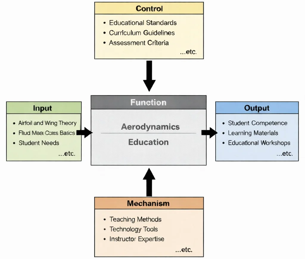
IDEF0 functional decomposition of Aerodynamics Education: fluid mechanics foundations and empirical flow data act as inputs regulated by aeronautical accreditation standards, transformed via computational tools and wind-tunnel experiments into verified engineering design competencies.

Aerodynamics: visualizing the distribution of continuous surface streamlines, circulation vectors, and pressure field gradients that generate aerodynamic lift, drag, and trim moments across the flight envelope.
A stylized, high-tech illustration of a futuristic aircraft cutting through flowing ribbons of air in blue and red, representing airflow patterns over and around the wings and fuselage. Behind the aircraft, faint technical overlays—charts, plots, and schematic-like diagrams—suggest wind-tunnel testing, computational fluid dynamics (CFD), and performance analysis. The overall image communicates the core idea of aerodynamics: predicting and controlling airflow to optimize stability, efficiency, and flight performance.
Airflow Interaction and Force Generation Systems
- \(\rho_\infty\): Freestream air density (\(\text{kg/m}^3\))
- \(V_\infty\): Freestream flight velocity (\(\text{m/s}\))
- \(\Gamma(y)\): Bound circulation distribution at spanwise location \(y\) (\(\text{m}^2/\text{s}\))
- \(C_L\): Total wing lift coefficient
- \(AR = b^2 / S\): Wing aspect ratio (wingspan squared over reference wing area)
- \(e\): Oswald planform efficiency span factor (\(0 < e \le 1.0\))
- \(C_{Di}\): Induced drag coefficient stemming from trailing vortex downwash
A medium-altitude long-endurance (MALE) reconnaissance aircraft operates in steady level cruise flight. Compute the total induced drag force \(D_i\), the downwash velocity \(w\) at the wing centerline, and the continuous shaft power \(P_{\text{induced}}\) expended solely to overcome vortex wake drag under the following flight parameters:
- Gross vehicle weight: \(W = 48,000 \text{ N}\) (In level cruise: \(L = W = 48,000 \text{ N}\))
- Wingspan: \(b = 20.0 \text{ m}\)
- Reference wing planform area: \(S = 25.0 \text{ m}^2\)
- True airspeed: \(V_\infty = 90.0 \text{ m/s}\)
- Ambient air density at cruise altitude: \(\rho_\infty = 0.909 \text{ kg/m}^3\)
- Oswald planform span efficiency factor: \(e = 0.92\)
Sequential Derivation & Calculation:
Step 1: Calculate the wing aspect ratio \(AR\):
$$AR = \frac{b^2}{S} = \frac{(20.0 \text{ m})^2}{25.0 \text{ m}^2} = \frac{400.0}{25.0} = 16.0$$Step 2: Calculate dynamic pressure \(q_\infty\):
$$q_\infty = \frac{1}{2} \rho_\infty V_\infty^2 = 0.5 \times 0.909 \text{ kg/m}^3 \times (90.0 \text{ m/s})^2 = 0.5 \times 0.909 \times 8100 = 3681.45 \text{ Pa}$$Step 3: Evaluate the required cruise lift coefficient \(C_L\):
$$C_L = \frac{L}{q_\infty S} = \frac{48,000 \text{ N}}{3681.45 \text{ Pa} \times 25.0 \text{ m}^2} = \frac{48,000}{92,036.25} = 0.5215$$Step 4: Compute the induced drag coefficient \(C_{Di}\):
$$C_{Di} = \frac{C_L^2}{\pi \cdot AR \cdot e} = \frac{(0.5215)^2}{\pi \times 16.0 \times 0.92} = \frac{0.2720}{46.244} = \mathbf{0.005882}$$Step 5: Calculate the dimensional induced drag force \(D_i\):
$$D_i = C_{Di} \cdot q_\infty \cdot S = 0.005882 \times 3681.45 \text{ Pa} \times 25.0 \text{ m}^2 = \mathbf{541.38 \text{ N}}$$Step 6: Compute the continuous propulsive power expended to overcome induced drag:
$$P_{\text{induced}} = D_i \times V_\infty = 541.38 \text{ N} \times 90.0 \text{ m/s} = 48,724.2 \text{ W} = \mathbf{48.72 \text{ kW}}$$Analysis: At high cruise altitudes where air density drops, maintaining equivalent lift requires higher angles of attack and increased \(C_L\). Because induced drag scales quadratically with \(C_L^2\), high-aspect-ratio wing design (\(AR = 16.0\)) and wingtip devices are essential to restrict induced power penalties to \(48.72 \text{ kW}\), directly extending flight endurance.
Aerospace & Aeronautical Hub
Brings together interacting subsystems that enable controlled motion through air and space within a comprehensive curriculum framework.
Aerodynamics
Examines how airflow generates lift, drag, pressure variations, boundary layers, and thermal effects on bodies moving through fluid media.
Flight Mechanics
Translates aerodynamic forces into vehicle equilibrium states, trim conditions, dynamic stability derivatives, and trajectory behavior.
Hypersonics & High-Speed Aerodynamics
Extends airflow analysis into extreme compressible flow regimes featuring shock waves, high expansion waves, and severe shock-layer heating.
Propulsion Systems
Analyzes intake pressure recovery, nozzle expansion dynamics, and internal fluid flow mechanics necessary to overcome aerodynamic drag.
Control Systems & Robotics
Adjusts control surfaces and active flow effectors to maintain vehicle stability and trajectory tracking across changing flight envelopes.
Avionics
Processes real-time Pitot-static and angle-of-attack air data inputs to support flight computer state estimation and pilot displays.
Aerospace Structures
Evaluates external aerodynamic pressure distributions to size structural spars, ribs, skins, and prevent aeroelastic structural divergence.
Aero Materials Science
Investigates surface smoothness, particle erosion resistance, and thermal protection coatings under extreme aerodynamic friction.
Spacecraft Engineering
Links atmospheric ascent and re-entry aerodynamic braking profile analysis to overall space mission architecture and thermal shield design.
Satellite Technology
Addresses rarefied atmospheric drag perturbations encountered by satellites operating in Low Earth Orbit (LEO).
Core Principles of Aerodynamics
Lift
- Lift is a fundamental aerodynamic force that acts perpendicular to the direction of oncoming airflow and is essential for achieving and sustaining flight. It allows aircraft to overcome their weight and maintain altitude. Without lift, heavier-than-air vehicles like airplanes could not fly.
- This force is primarily generated by the shape of the wing, known as the airfoil, which creates a pressure differential between the upper and lower surfaces. According to Bernoulli's Principle, faster airflow on the upper surface results in lower pressure compared to the bottom, generating lift.
- Several factors influence the magnitude of lift, including wing shape, size (wing area), angle of attack, airspeed, air density, and the viscosity of air. The wing's camber and aspect ratio are optimized based on the aircraft's purpose, whether for high-speed jets or gliders.
- Lift can also be augmented using high-lift devices such as flaps, slats, and vortex generators, which delay flow separation and stall. In modern aircraft, winglets at the tip reduce induced drag and improve lift-to-drag ratio, enhancing fuel efficiency.
- Innovative designs are also being explored, such as morphing wings and adaptive surfaces, to actively control lift in response to changing flight conditions. These techniques are a major area of research in both military and commercial aviation sectors.
- For an in-depth overview of how lift is generated, visit NASA's educational resource on Understanding Lift.
Drag
- Drag is the aerodynamic force that opposes an aircraft’s motion through the air. It acts parallel and opposite to the direction of flight and must be overcome by thrust to maintain speed and altitude.
- Drag is classified into different types. Parasite drag results from the aircraft’s shape, surface roughness, and protruding elements. It increases with speed and is minimized through streamlining and surface smoothing techniques.
- Induced drag, on the other hand, is a by-product of lift. As air flows around the wing, vortices form at the wingtips, causing downwash that increases drag. Winglets and optimized spanwise loading reduce this form of drag.
- Wave drag occurs when an aircraft approaches or exceeds the speed of sound. Shock waves form and cause a significant increase in resistance. Supersonic aircraft use swept wings, slender bodies, and area ruling to mitigate wave drag.
- Minimizing drag not only reduces fuel consumption but also enhances aircraft range and speed. Computational fluid dynamics (CFD) and wind tunnel testing are used extensively in drag reduction research.
- To learn more about types of aerodynamic drag and how they are controlled, refer to this comprehensive explanation from Skybrary: Aerodynamic Drag.
Thrust and Propulsion
- Thrust is the forward force that propels an aircraft through the air. It is generated by engines, such as jet turbines or propellers, and is designed to overcome drag. The balance between thrust and drag determines an aircraft’s acceleration or deceleration.
- Aerodynamics plays a crucial role in propulsion system efficiency. Air intakes, nozzles, and nacelle shapes are designed to ensure smooth airflow, minimizing pressure losses and maximizing thrust output.
- Jet engines function by compressing air, mixing it with fuel, igniting the mixture, and expelling hot gases to generate thrust. High-bypass turbofans used in commercial aviation are quieter and more fuel-efficient than older turbojets.
- In addition to traditional propulsion, innovations like electric propulsion and hybrid-electric systems are emerging to improve sustainability and reduce emissions.
- Designers must consider how engine placement affects aircraft stability and control, especially in modern blended-wing designs and unmanned aerial systems (UAS).
Boundary Layer and Flow Types
- The boundary layer is the thin layer of air in immediate contact with a surface, such as a wing or fuselage. It has a critical influence on skin friction drag, flow separation, and heat transfer.
- There are two main flow regimes within the boundary layer: laminar and turbulent. Laminar flow is smooth, orderly, and offers less resistance, while turbulent flow is chaotic and more resistant but adheres better to surfaces, reducing flow separation.
- Managing the boundary layer is vital for minimizing drag and avoiding stall. Techniques like boundary layer suction, vortex generators, and riblets are employed in high-performance aircraft to maintain controlled flow.
- Boundary-layer theory, developed by Ludwig Prandtl in the early 20th century, revolutionized aerodynamic design and is still foundational to current research and CFD modeling.
Angle of Attack and Stall
- The angle of attack (AoA) is the angle between the chord line of an airfoil and the direction of the oncoming airflow. It has a direct impact on lift generation and is a key parameter in flight dynamics.
- As AoA increases, lift also increases up to a critical point. Beyond this, airflow begins to separate from the upper surface, leading to stall—a sudden and dangerous loss of lift that can cause loss of control.
- To prevent stall, pilots are trained to monitor AoA indicators, and aircraft are equipped with stall warning systems and automated recovery mechanisms. Aerodynamic design features like leading-edge slats also delay stall by improving airflow adherence.
- Understanding stall behavior is especially important for aerobatic, military, and unmanned aircraft, where high maneuverability is required without compromising safety.
Contemporary AI-Era Computational Paradigms in Aerodynamics
Consider an embedded PINN evaluating local flow over an active morphing wing section at point \((x_0, y_0)\). The freestream air density is \(\rho = 1.20 \text{ kg/m}^3\) and dynamic viscosity is \(\mu = 1.80 \times 10^{-5} \text{ Pa}\cdot\text{s}\). The neural network outputs predict local horizontal velocity \(u = 45.0 \text{ m/s}\), vertical velocity \(v = 3.20 \text{ m/s}\), spatial velocity gradients \(\frac{\partial u}{\partial x} = 12.0 \text{ s}^{-1}\), \(\frac{\partial u}{\partial y} = -85.0 \text{ s}^{-1}\), and local pressure gradient \(\frac{\partial p}{\partial x} = -780.0 \text{ N/m}^3\). Viscous diffusion terms evaluate to \(\mu \left(\frac{\partial^2 u}{\partial x^2} + \frac{\partial^2 u}{\partial y^2}\right) \approx 0.045 \text{ N/m}^3\).
Step 1: Calculate the convective inertial acceleration term \(\rho \left( u \frac{\partial u}{\partial x} + v \frac{\partial u}{\partial y} \right)\):
$$\text{Inertia}_x = 1.20 \times \left[ (45.0 \times 12.0) + (3.20 \times -85.0) \right] = 1.20 \times [540.0 - 272.0] = 1.20 \times 268.0 = 321.60 \text{ N/m}^3$$Step 2: Calculate the net governing Navier-Stokes momentum residual \(\mathcal{R}_x\):
$$\mathcal{R}_x = \text{Inertia}_x + \frac{\partial p}{\partial x} - \mu \nabla^2 u = 321.60 + (-780.0) - 0.045 = -458.445 \text{ N/m}^3$$Step 3: Evaluate the loss contribution \(\mathcal{L}_{\text{physics}} = \|\mathcal{R}_x\|^2\) with scale factor \(\lambda = 1.0 \times 10^{-4}\):
$$\mathcal{L}_{\text{physics}} = 1.0 \times 10^{-4} \times (-458.445)^2 = 1.0 \times 10^{-4} \times 210,171.8 = \mathbf{21.02}$$Insight: This non-zero loss gradient backpropagates to update network weights, forcing the neural surrogate to satisfy physical momentum balance laws without requiring empirical CFD training datasets at every flight condition.
Applications of Aerodynamics
Aviation and Aerospace
- Aircraft Design:
- Modern aircraft rely heavily on aerodynamic shaping to ensure that lift is maximized while drag is minimized. The design of the wings, fuselage, tail, and control surfaces are all guided by aerodynamic performance metrics.
- Blended wing-body configurations reduce fuel consumption and improve lift-to-drag ratios. The implementation of advanced winglets helps reduce induced drag and turbulence, especially during takeoff and cruising.
- Computational Fluid Dynamics (CFD) tools are used extensively in the industry to simulate airflow patterns and optimize designs before physical prototypes are built.
- Supersonic and Hypersonic Flight:
- Travel beyond the speed of sound introduces complex aerodynamic challenges like shockwave management and intense heating. Aerodynamicists develop slender body designs and use materials like titanium alloys to withstand high thermal loads.
- Projects such as NASA’s X-59 Quiet Supersonic Technology aircraft are pushing the limits of aerodynamic design to reduce sonic booms and make supersonic travel over land feasible.
- Spacecraft Reentry:
- Space vehicles must survive the harsh conditions of atmospheric reentry, including intense heating and deceleration forces. Aerodynamic shaping is key to distributing heat and reducing structural stress.
- Reentry capsules like those used in SpaceX’s Crew Dragon or NASA’s Orion spacecraft are designed with ablative heat shields and spherical shapes to manage these extreme conditions.
- Aircraft Design:
Automotive Engineering
- Sports Cars: Performance vehicles are designed with streamlined profiles to reduce aerodynamic drag, allowing for higher speeds, better handling, and increased fuel efficiency.
- Electric Vehicles (EVs): As battery efficiency is critical, aerodynamic drag must be minimized to extend driving range. Designs often feature smooth underbodies, flush door handles, and airflow spoilers.
- Truck and Trailer Design: Aerodynamic deflectors and fairings are used on heavy vehicles to reduce turbulence and improve fuel economy on highways.
Wind Energy
- Wind turbine blade design relies on aerodynamic theory to convert wind into rotational energy with minimal resistance. Blade shapes are optimized using airfoil profiles similar to those in aircraft wings.
- Yaw control and pitch angle adjustments help maximize power output under varying wind conditions, and CFD simulations assist in farm-scale layout planning to avoid wake losses.
Sports and Recreation
- In professional sports, marginal gains from aerodynamic optimizations can decide championships. Cyclists use aero helmets and tight-fitting suits to reduce wind resistance, while swimmers wear specially designed suits to reduce drag in water.
- Even seemingly minor factors—like the dimple pattern on a golf ball—are the result of aerodynamic experimentation to optimize flight stability and distance.
- Athletes train in wind tunnels to fine-tune posture and movement for competitive edge.
Buildings and Structures
- Architects and engineers use wind tunnel testing and simulation to assess wind loads on tall structures. Buildings are often tapered, twisted, or perforated to reduce vortex shedding and oscillations.
- For suspension bridges and skyscrapers, aerodynamic form prevents destructive resonances such as those seen in the historical Tacoma Narrows Bridge collapse.
Military and Defense
- Military aircraft, including stealth fighters and surveillance drones, are designed with stealthy aerodynamic profiles to minimize radar cross-sections while maximizing maneuverability.
- Missiles are engineered for supersonic travel with minimal drag, using fins and control surfaces shaped by decades of aerodynamic research.
Advances in Aerodynamics
Computational Fluid Dynamics (CFD)
- CFD has emerged as a cornerstone of aerodynamic analysis, enabling engineers to simulate and visualize airflow around complex geometries with incredible accuracy.
- Advanced CFD software allows for the modeling of turbulence, boundary layers, and flow separation under varying atmospheric conditions, significantly reducing reliance on costly wind tunnel experiments.
- Applications span from commercial aircraft and Formula One vehicles to wind turbines and HVAC systems, where airflow behavior is critical.
- Emerging methods such as Large Eddy Simulations (LES) and Direct Numerical Simulations (DNS) push the boundaries of turbulence modeling, though they require significant computational resources.
- By integrating CFD with AI-driven optimization algorithms, engineers can now run design iterations automatically and converge on the most efficient configurations faster than ever before.
Biomimicry in Aerodynamics
- Nature has long been an inspiration for efficient aerodynamic forms. Birds, insects, and aquatic animals possess naturally optimized shapes that reduce drag and enhance control.
- For instance, the study of owl wings has informed silent drone design, while the skin texture of sharks has inspired surface coatings that reduce flow separation.
- Wind turbine blades have also adopted features inspired by humpback whale fins—namely, tubercles—that improve lift and delay stall.
- As materials science advances, engineers are increasingly able to replicate biological flexibility and microstructures in engineered surfaces.
- This interdisciplinary approach merges biology, fluid dynamics, and mechanical engineering to unlock highly efficient solutions.
Adaptive and Morphing Structures
- Unlike traditional fixed structures, morphing aerodynamic surfaces can change their shape in response to real-time flow conditions.
- Examples include aircraft wings that flex for optimal lift-to-drag ratio and car spoilers that automatically adjust at high speeds.
- Shape memory alloys, electroactive polymers, and pneumatic actuators are enabling this innovation in both civil and military aerospace sectors.
- Morphing technology contributes to quieter, more agile, and more fuel-efficient designs, especially in UAVs and small aircraft.
- In automotive applications, adaptive grilles and underbody panels help manage cooling airflow and drag reduction simultaneously.
Energy Efficiency and Sustainability
- Energy consumption and environmental impact are driving factors behind aerodynamic improvements in transportation and infrastructure.
- Streamlined body shapes in electric vehicles (EVs) and aircraft reduce drag, extending battery range or reducing fuel burn respectively.
- In rail systems, nose cone design and bogie fairings contribute to energy-efficient high-speed trains by reducing wake turbulence.
- Infrastructure like wind turbines and even buildings are being reimagined to minimize drag while optimizing natural ventilation and energy generation.
- Smart city planners use aerodynamics to manage urban airflow, which helps reduce heat islands and improve air quality in dense metropolitan areas.
Noise Reduction
- Noise pollution, particularly from aircraft and urban vehicles, poses both environmental and health challenges.
- Engineers are designing quieter aircraft using serrated trailing edges (chevrons), noise-absorbing nacelle linings, and revised flap systems.
- In the automotive sector, improvements in mirror design, undercarriage smoothing, and tire airflow channeling reduce wind noise at high speeds.
- Urban noise barriers and building facades are also being redesigned with aerodynamic principles to redirect or absorb traffic noise.
- Ultimately, aerodynamic noise control contributes to compliance with environmental regulations and improves quality of life in populated areas.
- ANSYS Fluent - CFD Software for Aerodynamics
- ScienceDaily: Latest Aerodynamics Research
Aerodynamics: Challenges and Future Directions
- Supersonic and Hypersonic Flight: High-speed flight presents extreme challenges in aerodynamics, especially related to heat generation, wave drag, and structural stress. At Mach 5 and above, vehicles experience temperatures exceeding 1,000°C due to air compression and friction. This demands the development of heat-resistant materials, advanced cooling systems, and innovative aerodynamic shapes that minimize drag while maintaining stability. Design strategies such as wave-rider configurations, spike-nose cones, and adaptive leading edges are actively explored to manage shockwave behavior and prevent boundary layer separation. New programs, such as NASA's X-59 and various hypersonic weapon initiatives, continue to push forward the limits of speed and control in the upper atmosphere, driving breakthroughs in computational simulations, wind tunnel testing, and material science. Managing the trade-off between efficiency and thermal survivability will remain a core research priority for years to come.
- Urban Air Mobility: The rise of electric vertical takeoff and landing (eVTOL) aircraft introduces new aerodynamic considerations for operating in urban environments. Compact, multi-rotor designs must balance lift, noise, turbulence, and maneuverability within confined airspace. Unlike traditional aircraft, UAM vehicles face frequent transitions between hover and forward flight modes, which require highly adaptable aerodynamic control strategies. Additionally, minimizing rotor blade noise and optimizing airflow around buildings are essential for public acceptance and regulatory approval. Computational models and small-scale wind tunnel tests are increasingly used to validate performance and safety. Aerodynamic engineers must also address wind shear, thermal plumes, and downdrafts common in cityscapes to ensure reliable operations.
- Climate Resilience: As climate change intensifies, vehicles and structures must be designed to withstand more extreme weather conditions, including stronger winds, heavier rainfall, and higher temperatures. Aerodynamic optimization plays a crucial role in protecting buildings, bridges, and transportation systems from these impacts. Engineers use wind simulation models to understand how high-rise structures interact with gusts and vortices during storms. In aviation, aircraft need improved aerodynamic designs to handle sudden turbulence and variations in air density. Aerodynamically adaptive features—such as morphing wings and active airflow control surfaces—offer the potential to adjust in real time to unpredictable weather, enhancing both safety and efficiency. These innovations also support global sustainability goals by reducing drag-induced fuel consumption.
- Space Exploration: While space is largely a vacuum, aerodynamic principles remain vital for planetary exploration missions that involve descent and landing through foreign atmospheres. For instance, Mars' thin atmosphere requires unique aerodynamic approaches that differ greatly from those used on Earth. Parachute deployment, heat shield design, and aerodynamic braking systems must be carefully modeled to ensure safe landings. Future missions to Venus, Titan, or exoplanets will require entirely new frameworks for understanding fluid dynamics under varying pressures and chemical compositions. Aerodynamicists are also researching reusable launch systems and spaceplanes that operate both in the atmosphere and in space, requiring highly optimized shapes and thermal protection systems that can withstand multiple entries and exits.
- NASA Aeronautics Research Mission Directorate
- AIAA Journal on Aerospace Sciences
Engineering Trade-offs in Aerodynamic Design
| Aerodynamic Trade-off | Primary Flight Benefit | Systemic Penalty / Risk | Quantitative Design Metric |
|---|---|---|---|
| High Aspect Ratio (\(AR\)) vs. Structural Weight | Minimizes induced drag (\(C_{Di} \propto 1/AR\)); drastically improves high-altitude cruise fuel efficiency. | Increases root bending moments; demands heavier internal spar caps; elevates aeroelastic flutter susceptibility. | Aspect Ratio: Commercial Transport (\(AR \approx 9\text{--}11\)); Sailplanes (\(AR \approx 25\text{--}32\)); Fighters (\(AR \approx 3\text{--}4\)). |
| Wing Sweepback vs. Low-Speed Handling | Increases critical Mach number (\(M_{\text{crit}}\)); delays transonic wave drag rise and local supersonic shock formation. | Induces spanwise boundary layer cross-flow; promotes premature wingtip stall, triggering dangerous uncommanded pitch-up. | Sweep Angle (\(\Lambda\)): Subsonic (\(0^\circ\)); Transonic Transport (\(28^\circ\text{--}35^\circ\)); Supersonic (\(45^\circ\text{--}60^\circ\)). |
| Airfoil Thickness Ratio (\(t/c\)) Trade-off | Thicker sections (\(t/c \approx 15\%\)) provide internal fuel volume and high structural spar depth with benign stall. | Accelerates local surface airflow to supersonic speeds early, precipitating severe transonic shock drag. | Thickness-to-Chord Ratio: Low-Speed General Aviation (\(t/c \approx 12\text{--}16\%\)); Transonic/Supersonic (\(t/c \approx 4\text{--}9\%\)). |
| Laminar Flow Control vs. Surface Maintenance | Extended natural laminar flow (NLF) lowers profile skin friction drag by up to 60% compared to turbulent flow. | Extremely fragile; microscopic insect strikes, rivet heads, or atmospheric ice trip immediate turbulent transition. | Critical Transition Reynolds Number: \(Re_x \approx 5 \times 10^5\) (Natural) to \(Re_x > 10^7\) (Active Suction). |
An airliner cruises at Mach \(M_\infty = 0.82\). An unswept wing (\(\Lambda = 0^\circ\)) with supercritical airfoil has a critical Mach number \(M_{\text{crit}} = 0.74\), placing the aircraft deep into transonic drag divergence where wave drag coefficient surges by \(\Delta C_{Dw} = +0.0180\). Applying a quarter-chord wing sweep angle \(\Lambda = 32^\circ\) reduces the effective normal Mach number component to:
$$M_{\text{eff}} = M_\infty \cos(\Lambda) = 0.82 \times \cos(32^\circ) = 0.82 \times 0.8480 = \mathbf{0.695}$$Comparison: Because \(M_{\text{eff}} = 0.695 < M_{\text{crit}} = 0.74\), airflow perpendicular to the leading edge remains fully subsonic, completely eliminating wave drag at the expense of requiring leading-edge Krueger flaps to mitigate tip stall during airport landing approaches.
Why Study Aerodynamics
Forces Acting on Aircraft
Design and Performance Optimization
Supersonic and Hypersonic Regimes
Environmental and Noise Considerations
Applications in Vehicles Beyond Aircraft
Interactive Airfoil Lift and Drag Polar Simulator
Interactive runtime environment: https://prep4uni.online/stem/physical-technologies/aerospace-and-aeronautical-engineering/aerodynamics/
Interactive Concept Review
Why does increasing wing aspect ratio reduce induced drag coefficient (\(C_{\text{Di}}\))?
What physical fluid phenomenon triggers aerodynamic stall beyond critical angle of attack?
How do shock waves generate wave drag during transonic and supersonic flight?
Frequently Asked Questions on Aerodynamics
These FAQs help you connect core aerodynamic ideas to real vehicles, from aircraft and cars to wind turbines and sports equipment.
What does aerodynamics study in the context of engineering?
Aerodynamics studies how air flows around and through objects, and how that flow generates forces such as lift and drag. In engineering, it focuses on shaping wings, fuselages, vehicle bodies and turbine blades so that they interact with the air in a controlled and efficient way. Good aerodynamic design improves performance, stability, noise, and energy use.
Why are lift and drag the two most important aerodynamic forces for aircraft?
Lift is essential because it counteracts the weight of the aircraft and allows it to take off, climb and stay in the air. Drag opposes the motion of the aircraft and must be overcome by the engines, so excessive drag wastes fuel and limits range. Aerodynamic design aims to maximise useful lift while minimising drag, so that aircraft can fly safely, efficiently and economically.
How does streamlining reduce aerodynamic drag on vehicles?
Streamlining reduces drag by shaping the body so that air can flow smoothly over it with as little separation and turbulence as possible. Rounded leading edges, tapered tails and carefully designed transitions between surfaces all help the flow remain attached. This reduces pressure differences and energy loss in the wake, which in turn lowers drag and improves fuel efficiency or speed.
What is a boundary layer and why is it important?
The boundary layer is a thin region of air close to a surface where friction slows the flow from the free-stream speed down to nearly zero at the wall. Its behaviour (laminar or turbulent) has a strong influence on skin-friction drag and on whether the flow separates from the surface. Understanding and managing the boundary layer is one of the key tasks in aerodynamic design for wings, car bodies and turbine blades.
How does aerodynamic design improve the safety and stability of road vehicles?
Aerodynamic design can reduce unwanted lift, side forces and buffeting that might make a vehicle feel light or unstable at higher speeds. Features such as spoilers, diffusers and underbody panels are used to manage pressure distribution and direct the airflow. This helps keep tyres firmly on the road, improves handling in crosswinds and contributes to predictable, safe behaviour for drivers.
In what ways is aerodynamics important for wind turbines and renewable energy?
For wind turbines, aerodynamics determines how efficiently blades convert the kinetic energy of moving air into rotational power. The blade shape, twist and angle of attack must be tuned to achieve high lift with manageable drag over a wide range of wind speeds. Better aerodynamic design directly increases the energy captured per turbine and lowers the cost of wind-generated electricity.
How are sports and athletics influenced by aerodynamic principles?
Aerodynamic principles influence the design of bicycles, helmets, racing suits, balls and even stadiums. Athletes and equipment designers work to reduce drag and control lift so that motion through the air wastes less energy and trajectories are more predictable. Small changes in shape or posture can lead to measurable gains in speed, distance or accuracy in many sports.
What tools do engineers use to analyse aerodynamic performance?
Engineers use a combination of wind tunnel testing, computational fluid dynamics (CFD) simulations and sometimes full-scale flight or road tests. Wind tunnels provide controlled experimental data; CFD allows detailed visualisation of flow fields and forces in a virtual environment. By comparing and refining results from both methods, designers can iteratively improve shapes before committing to full-scale prototypes.
End-of-Page Comprehensive Practice Module
Foundational Concept Review
- What is the primary focus of aerodynamics? Answer: The primary focus of aerodynamics is to understand how air flows around and through solid objects and how that flow generates forces such as lift, drag, and side forces.
- How does reducing aerodynamic drag benefit vehicles and aircraft? Answer: Reducing aerodynamic drag lowers the thrust or power needed to maintain a given airspeed, directly improving fuel efficiency, extending operational range, and reducing carbon emissions.
- What role does lift play in aviation? Answer: Lift is the upward aerodynamic force acting perpendicular to the relative wind that counteracts the weight of the aircraft, enabling take-off, climb, cruise, and landing.
- Why is minimising turbulence important in aerodynamic design? Answer: Excessive turbulent flow separation increases parasite drag, noise, and unsteady aerodynamic loading, which impairs flight efficiency and structural life.
- In which industries are aerodynamic principles commonly applied? Answer: Aerodynamics is applied in aerospace, automotive design, wind turbine energy generation, civil structural architecture, and athletic equipment engineering.
- What is the relationship between airflow patterns and aerodynamic performance? Answer: Smooth, attached airflow preserves steady pressure gradients that optimize high lift-to-drag ratios, whereas separated flow causes low-pressure turbulent wakes that drastically increase drag.
- How does aerodynamic design contribute to vehicle safety? Answer: Proper aerodynamic design suppresses unwanted lift, delays wing stall, and stabilizes vehicles during severe atmospheric turbulence or crosswinds.
- What is the significance of aerodynamic studies in wind energy systems? Answer: Optimizing wind turbine blade airfoils increases aerodynamic torque extraction efficiency from incoming wind currents, lowering clean energy generation costs.
Analytical & Systems Engineering Challenges
- How might advancements in aerodynamics influence the future of sustainable transportation? Answer: Advanced drag-reduction shaping and active flow control drastically reduce energy consumption per passenger-kilometer, making electric aviation and long-range electric road vehicles commercially viable.
- In what ways can biomimicry inspire innovative aerodynamic designs? Answer: Biomimicry adopts natural evolutionary shapes—such as whale flipper tubercles to delay wing stall, owl feather serrations for silent flight, and sharkskin riblets to lower skin friction drag.
- How do environmental factors like temperature and humidity affect aerodynamic performance? Answer: Temperature and humidity alter air density (\(\rho\)) and dynamic viscosity (\(\mu\)). Higher temperature or humidity reduces ambient density, decreasing lift generation and engine thrust output.
- What are the challenges in balancing aerodynamic efficiency with aesthetic design in consumer products? Answer: Highly streamlined aerodynamic forms may conflict with interior cabin volume, safety crashworthiness zones, or brand styling aesthetics, requiring multi-objective design optimization.
- How can computational fluid dynamics (CFD) simulations enhance our understanding of complex aerodynamic phenomena? Answer: CFD solves Navier-Stokes equations numerically across millions of grid cells, allowing visualization of internal vortex core dynamics, shock wave interactions, and acoustic noise generation.
- What role does aerodynamics play in the design of high-performance sports equipment? Answer: Minimizing drag through streamlined cycling helmets, textured skinsuits, and golf ball dimples enables athletes to maximize speed and distance with equal physical exertion.
- What are the potential aerodynamic challenges in developing vehicles for extraterrestrial exploration? Answer: Foreign atmospheres (e.g., Mars) present extremely low air density (\(\approx 1\%\) of Earth) and high \(\text{CO}_2\) gas compositions, requiring specialized large-surface airfoils and high-Mach parachute deceleration systems.
Quantitative Calculations & Applied Analysis
- Calculate dynamic pressure (\(q\)) in Pascals for an aircraft flying at velocity \(V = 80 \text{ m/s}\) at an altitude where air density \(\rho = 1.05 \text{ kg/m}^3\).
Answer:
Step 1: Formula: \(q = \frac{1}{2} \rho V^2\)
Step 2: Substitute values: \(q = 0.5 \times 1.05 \text{ kg/m}^3 \times (80 \text{ m/s})^2 = 0.5 \times 1.05 \times 6400\)
Step 3: \(q = \mathbf{3,360 \text{ Pa}} \quad (3.36 \text{ kPa})\) - An aircraft wing with planform area \(S = 35 \text{ m}^2\) generates a total lift force \(L = 70,000 \text{ N}\) at dynamic pressure \(q = 4,000 \text{ Pa}\). Calculate the lift coefficient (\(C_{\text{L}}\)).
Answer:
Step 1: Formula: \(C_{\text{L}} = \frac{L}{q \cdot S}\)
Step 2: Substitute values: \(C_{\text{L}} = \frac{70,000 \text{ N}}{4000 \text{ Pa} \times 35 \text{ m}^2} = \frac{70,000}{140,000}\)
Step 3: \(C_{\text{L}} = \mathbf{0.50}\) - Calculate the total drag force (\(D\)) in Newtons for a drone with drag coefficient \(C_{\text{D}} = 0.04\), wing area \(S = 1.2 \text{ m}^2\), flying at velocity \(V = 25 \text{ m/s}\) in standard sea-level air (\(\rho = 1.225 \text{ kg/m}^3\)).
Answer:
Step 1: Calculate dynamic pressure: \(q = 0.5 \times 1.225 \times (25)^2 = 0.5 \times 1.225 \times 625 = 382.8125 \text{ Pa}\)
Step 2: Calculate drag: \(D = C_{\text{D}} \cdot q \cdot S = 0.04 \times 382.8125 \text{ Pa} \times 1.2 \text{ m}^2\)
Step 3: \(D = \mathbf{18.38 \text{ N}}\) - Calculate the Reynolds number (\(Re\)) for an airfoil with chord length \(c = 1.5 \text{ m}\) flying at velocity \(V = 50 \text{ m/s}\) in air with kinematic viscosity \(\nu = 1.5 \times 10^{-5} \text{ m}^2/\text{s}\).
Answer:
Step 1: Formula: \(Re = \frac{V \cdot c}{\nu}\)
Step 2: Substitute values: \(Re = \frac{50 \text{ m/s} \times 1.5 \text{ m}}{1.5 \times 10^{-5} \text{ m}^2/\text{s}} = \frac{75}{1.5 \times 10^{-5}}\)
Step 3: \(Re = \mathbf{5,000,000} \quad (5.0 \times 10^6)\) - Determine the induced drag coefficient (\(C_{\text{Di}}\)) for an elliptic wing generating a lift coefficient \(C_{\text{L}} = 0.80\), given an aspect ratio \(AR = 10.0\) and Oswald efficiency factor \(e = 1.0\).
Answer:
Step 1: Formula: \(C_{\text{Di}} = \frac{C_{\text{L}}^2}{\pi \cdot AR \cdot e}\)
Step 2: Denominator: \(\pi \times 10.0 \times 1.0 = 31.4159\)
Step 3: \(C_{\text{Di}} = \frac{(0.80)^2}{31.4159} = \frac{0.64}{31.4159} \approx \mathbf{0.02037}\) - An aircraft in steady level flight has a Lift-to-Drag ratio (\(L/D\)) \(= 18.0\). If the aircraft gross weight is \(90,000 \text{ N}\), calculate the required total thrust (\(T\)) from the engines to maintain constant speed.
Answer:
Step 1: In steady level flight: \(L = W = 90,000 \text{ N}\), and \(T = D\)
Step 2: Calculate drag: \(D = \frac{L}{L/D} = \frac{90,000 \text{ N}}{18.0} = 5,000 \text{ N}\)
Step 3: Required Thrust \(T = \mathbf{5,000 \text{ N}} \quad (5.0 \text{ kN})\) - Calculate the local speed of sound (\(a\)) in \(\text{m/s}\) for atmospheric air at temperature \(T = 288.15 \text{ K}\), given specific heat ratio \(\gamma = 1.4\) and specific gas constant \(R = 287.05 \text{ J}/(\text{kg}\cdot\text{K})\).
Answer:
Step 1: Formula: \(a = \sqrt{\gamma \cdot R \cdot T}\)
Step 2: Substitute values: \(a = \sqrt{1.4 \times 287.05 \times 288.15} = \sqrt{115,808.82}\)
Step 3: \(a \approx \mathbf{340.31 \text{ m/s}}\)