
In Robotics and Automation in EE Education, students don’t just “wire things up”—they learn to make machines behave on purpose. They begin with real components and data from the physical world, then work within safety rules and ethical limits that matter the moment a robot moves near people or infrastructure. Using programming environments and robotics kits as their workshop, they practise the full loop: sensing, decision-making, actuation, and iteration. By the end, the outputs are tangible—automation solutions and working robotic projects—but the deeper product is disciplined engineering judgment: how to build systems that are not only clever, but dependable, testable, and safe to deploy.
While the Robotics hub develops the computational foundations of perception, planning, and control, this page focuses on how those principles are physically realized through electrical and electronic engineering. Circuits, power electronics, embedded processors, communication interfaces, and signal conditioning hardware transform abstract control laws into reliable physical motion.
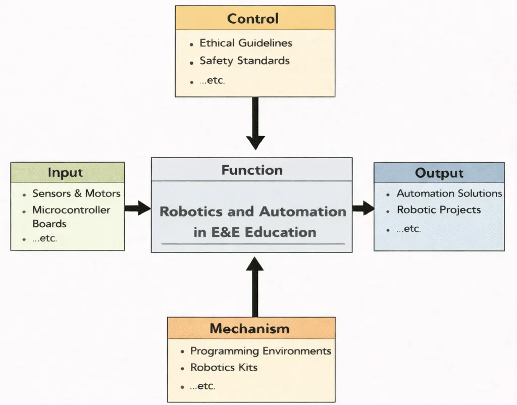
This IDEF0 diagram summarizes Robotics and Automation in E&E Education as a structured learning pipeline. On the left, learners start from practical building blocks such as sensors, motors, and microcontroller boards. Above, ethical guidelines and safety standards govern what is acceptable, safe, and responsible. Below, enabling tools—programming environments and robotics kits—provide the means to design, test, and refine. These elements converge in the central function, producing outcomes on the right: automation solutions and complete robotic projects, along with related competencies and deliverables.

The image depicts a high-tech automation facility where multiple robotic systems operate in the same workspace: articulated industrial arms, a humanoid robot at the center, and drones moving overhead. Engineers stand nearby, suggesting human–machine collaboration rather than fully unmanned operation. The floor and surrounding air are layered with translucent interface graphics—charts, signals, and AI icons—hinting at the electrical and electronic backbone of robotics: sensors and feedback loops, motor drives and power electronics, embedded control, machine vision, communication links, and real-time monitoring. Overall, the scene communicates how robotics and automation integrate hardware, software, and data to create coordinated, precise, and increasingly intelligent systems for modern industry and services.
Robotics & Automation: Curriculum Roadmap & Cluster Navigation
Electrical & Electronic Engineering – Overview
Serves as the overarching foundational node, establishing how physical signal transformation, semiconductor behavior, electromagnetic theory, and energy processing form the substrate for intelligent systems.
Robotics & Automation in EE (Current Page)
Combines sensors, actuators, power electronics, embedded microcontrollers, and real-time control algorithms to convert algorithmic intent into physical, autonomous, and safe electromechanical motion.
Control Systems Engineering
Provides the rigorous analytical framework—including transfer functions, state-space models, stability margins, and PID tuning—necessary to stabilize robotic joints and maintain trajectory tracking under dynamic loading.
Signal Processing
Delivers mathematical filtering, Fourier transforms, and digital noise suppression required to clean raw, noisy sensor streams (encoder counts, LiDAR, IMUs) before feeding them into high-level state estimation loops.
Embedded Systems & Microelectronics
Explores the microcontrollers, FPGAs, DSPs, and RTOS environments that execute low-latency deterministic code, directly bridging software logic with real-time hardware actuation.
Instrumentation & Measurement
Focuses on the physical principles, sensitivity limits, and calibration techniques of physical transducers (optical encoders, strain gauges, Hall-effect sensors) that provide essential state feedback to the robot.
IoT & Smart Technologies
Extends isolated robotic operation into interconnected fleet automation, allowing edge-computing robots to share diagnostic metrics, sensor maps, and operational workloads via cloud infrastructure.
Communication Engineering
Examines real-time deterministic fieldbus protocols (CAN bus, EtherCAT) and wireless telemetry that allow controllers, sensors, and actuators to exchange time-critical control packets without packet collision or delay.
Electronics Engineering
Covers discrete electronic components, PCB design layouts, gate drivers, and analog amplification stages that form the hardware interface between low-voltage logic chips and high-power actuators.
Biomedical Electronics
Translates robotic automation into medical environments, focusing on ultra-precise surgical manipulators, active prosthetics, exoskeletons, and bio-compatible sensor interfaces.
Power Systems Engineering
Addresses bulk grid interaction, industrial distribution voltages, and high-voltage delivery systems required to power large-scale manufacturing robotics and automated heavy infrastructure.
Renewable Energy & Energy Storage
Investigates high-density battery chemistries, BMS management, supercapacitors, and energy-harvesting technologies that determine the operational untethered lifespan of mobile autonomous robots.
Quantum Electronics
Pushes the frontier of robotics toward ultra-sensitive quantum sensing, atomic-scale navigation without GPS, and next-generation solid-state processing units.
Power Electronics and Motor Drive Systems
Robotic motion depends on precise energy conversion. Motors require controlled voltage and current profiles to generate accurate torque. Electrical engineers design the circuits that deliver this energy safely and efficiently.
Key technologies include:
- Pulse-width modulation (PWM) motor control
- H-bridge and three-phase inverter topologies
- Field-oriented control (FOC) implementations
- Current sensing and feedback circuitry
- Thermal management and heat dissipation systems
Switching frequency, electromagnetic interference (EMI), and efficiency constraints directly affect robotic responsiveness and stability. Power electronics therefore form the energetic backbone of robotic actuation, complementing the mechanical structures described in Actuation and Mechanical Design in Robotics.
Embedded Control Architecture
Robotic controllers operate on embedded platforms such as microcontrollers, digital signal processors (DSPs), field-programmable gate arrays (FPGAs), and system-on-chip (SoC) architectures. These devices execute control algorithms in real time, translating feedback signals into actuator commands.
Critical design considerations include:
- Analog-to-digital converter (ADC) resolution and sampling frequency
- Interrupt latency and deterministic timing
- Memory constraints and computational throughput
- Encoder decoding and pulse measurement accuracy
- Real-time operating system (RTOS) integration
Hardware-level timing precision is essential for stable closed-loop control, as developed in Advanced Control Systems in Robotics. Electrical engineers ensure that theoretical control laws remain stable when executed on physical processors.
Sensor Interface and Signal Conditioning
Sensors provide the raw data required for robotic perception. However, these signals are often analog, noisy, and susceptible to distortion. Electrical engineering ensures that measurements are accurate before they reach higher-level perception algorithms.
Typical interface challenges include:
- Low-noise amplifier design
- Anti-aliasing filtering
- Shielding and grounding strategies
- Isolation and protection circuitry
- Calibration and drift compensation
Signal conditioning ensures reliable input for Sensors and Perception in Robotics, particularly in electrically noisy industrial environments.
Communication and Distributed Control Networks
Modern robotic systems rarely operate as isolated devices. Distributed architectures require robust communication between processors, sensors, and actuators.
- CAN bus and industrial fieldbus systems
- EtherCAT and real-time Ethernet protocols
- SPI and I2C peripheral interfaces
- Wireless telemetry for mobile robots
Network latency, synchronization accuracy, and fault tolerance directly influence system-level stability. These hardware communication layers support the distributed software architectures described in Robotics Middleware and Distributed Systems.
Contemporary Computational Paradigms in Modern Robotics & Automation
Advanced robotic automation demands sub-millisecond physical coordination across multi-degree-of-freedom manipulators and autonomous mobile robots (AMRs). Modern paradigms bridge physical electrodynamics with data-driven neural modeling:
- Physics-Informed Neural Networks (PINNs) in Robot Dynamics: Rigid body dynamics formulated via the Euler-Lagrange equations suffer from model parameter uncertainties (non-linear joint friction, gear backlash, cable elasticity). PINNs embed the manipulator equation directly into training losses: $$\mathcal{L}_{\text{total}} = \mathcal{L}_{\text{data}} + \lambda_{\text{dyn}} \left\| \mathbf{M}(\mathbf{q})\ddot{\mathbf{q}} + \mathbf{C}(\mathbf{q}, \dot{\mathbf{q}})\dot{\mathbf{q}} + \mathbf{g}(\mathbf{q}) + \mathbf{\tau}_{\text{friction}}(\dot{\mathbf{q}}) - \mathbf{\tau}_{\text{applied}} \right\|^2$$ This enables embedded motor microcontrollers to execute real-time adaptive feedforward torque compensation without expensive offline calibration.
- Lie-Group Invariant Extended Kalman Filters (IEKF) for Robotic Odometry: Legged humanoids and aerial drones navigating GPS-denied factory floors fuse inertial measurement units (IMUs), optical wheel encoders, and LiDAR. Formulating the state estimator on the matrix Lie group \(SE_2(3)\) ensures that estimation errors remain invariant to global coordinates, guaranteeing deterministic covariance convergence.
- Fourier Neural Operators (FNOs) for Soft Robotic Deformation Modeling: Continuously deformable soft robotic grippers exhibit infinite-dimensional continuum mechanics governed by non-linear hyperelastic partial differential equations. FNOs learn mesh-independent operator mappings from actuation pneumatic pressure inputs directly to 3D deformation manifolds, executing forward predictions in under \(5\,\text{ms}\).
- Real-Time Digital Twins & Automated Predictive FDIR: Automated workcells maintain synchronized digital twins tracking physical joint currents and vibration spectra. Model-based Fault Detection, Isolation, and Recovery (FDIR) algorithms detect winding insulation breakdown or gear tooth pitting weeks before mechanical seizure occurs.
Industrial Automation and Smart Manufacturing
Electrical and electronic engineering also plays a central role in industrial automation systems where robotics integrates with programmable logic controllers (PLCs), supervisory control systems, and Industry 4.0 infrastructure.
Applications include:
- Automated assembly lines
- Industrial robot drive systems
- Machine vision integration
- Predictive maintenance monitoring
Here, robotics becomes part of a larger cyber-physical system, where electrical infrastructure ensures reliability, safety, and scalability.
Applications of Robotics and Automation in Electrical & Electronic Engineering
The practical execution of robotics and automation spans from sub-millimeter electronic board inspection to heavy automated assembly lines. To evaluate how real-time embedded control handles actuator drives under variable operational loads, interact with the simulation below.
Interactive Motor Drive & Closed-Loop Response Simulator
Simulate real-time PWM H-bridge motor actuation under closed-loop proportional feedback. Adjust PWM duty cycle, mechanical load torque, and controller gain to observe current draw, rotational speed response, and continuous timeline tracking.
Engineering Constraints and Trade-offs
- Switching efficiency vs electromagnetic noise
- Processor performance vs power consumption
- High-frequency control vs thermal dissipation
- Sensor precision vs circuit complexity
- Redundancy vs system cost
Electrical design choices influence not only performance but also long-term durability and safety. In robotics, hardware limitations often define the achievable precision of control algorithms.
Systems Engineering Architecture: Trade-Off Analysis
Designing modern robotic automation systems requires balancing actuator power density, deterministic communications, sensor fidelity, and real-time computation. The following matrix illustrates key engineering compromises in robotic system architecture:
| Design Domain | Architectural Choice | Favorable Attributes (+) | Compromised Metrics (−) | System Mitigation Strategy |
|---|---|---|---|---|
| Actuator Commutation | Field-Oriented Control (FOC) vs. Trapezoidal Commutation | Near-zero torque ripple; maximum electrical efficiency; smooth low-speed joint compliance. | Requires high-resolution absolute encoders and real-time trigonometric coordinate transformations (Clarke/Park). | Deploy dedicated hardware CORDIC coprocessors or DSP motor control ICs. |
| Fieldbus Communication | EtherCAT vs. Controller Area Network (CAN FD) | Sub-microsecond synchronization jitter; high bandwidth (100 Mbps); allows synchronized multi-axis servo control. | High per-node hardware cost (dedicated ESC silicon required); fragile point-to-point daisy-chain physical wiring. | Hybrid architecture: EtherCAT for high-speed multi-axis arm servos, CAN FD for auxiliary gripper and sensor nodes. |
| Actuator Type | Quasi-Direct Drive (QDD) vs. High-Ratio Strain Wave (Harmonic) Drive | High backdrivability; low reflected inertia; transparent proprioceptive force sensing for legged robotics. | Lower peak holding torque; high continuous motor current heating; requires large-diameter outrunner BLDC motors. | Thermally enhanced stator potting and optimized low-gear planetary transmissions (\(\le 10:1\)). |
| State Estimation | Visual-Inertial Odometry (VIO) vs. 3D LiDAR Odometry | Extremely lightweight; low power consumption; low unit bill-of-materials cost. | Degrades in featureless or low-light industrial environments; computational drift over long distances. | Multi-sensor fusion integrating wheel odometry, IMU, and sparse LiDAR landmark mapping. |
Preparation for University-Level Study
Students approaching robotics from an electrical and electronic engineering perspective should develop strong foundations in:
- Analog and digital circuit design
- Power electronics and motor control
- Signal processing
- Embedded systems programming
- Control hardware implementation
- Communication networks
Robotics, when viewed through electrical engineering, reveals how intelligence is powered, transmitted, amplified, filtered, and executed. It is here that mathematics becomes voltage, computation becomes current, and algorithms become motion.
Robotics Across Engineering Disciplines
Robotic systems draw on multiple engineering foundations. While this page focuses on the electrical and electronic implementation layer, robotics is equally shaped by mechanical structures and aerospace control systems. Explore how robotics is embodied across disciplines:
Robotics and Automation in Electrical & Electronic Engineering
Focuses on power electronics, embedded control hardware, signal conditioning, communication networks, and the electrical infrastructure that enables robotic intelligence to operate reliably.
Robotics and Automation in Mechanical Engineering
Emphasizes structural mechanics, kinematics, actuator integration, load distribution, and physical embodiment of robotic systems in industrial and manufacturing environments.
Aero Control Systems and Robotics
Explores flight dynamics, stability margins, guidance systems, telemetry constraints, and autonomous control in aerial and aerospace robotic platforms.
Frequently Asked Questions
1. Why is power electronics essential in robotic systems?
Robotic actuators require precise control of voltage and current to generate stable torque and motion. Power electronics — including inverters, H-bridge circuits, and pulse-width modulation (PWM) control — enable efficient energy conversion while minimizing heat loss and electrical noise. Without well-designed motor drive systems, even advanced control algorithms cannot perform reliably.
2. How do embedded systems influence robotic performance?
Embedded processors execute control algorithms in real time. Sampling frequency, interrupt latency, ADC resolution, and computational throughput directly affect system stability and responsiveness. Electrical engineers ensure that theoretical control strategies operate correctly when implemented on physical hardware.
3. What challenges arise in sensor signal conditioning for robotics?
Sensors often produce low-amplitude analog signals that are susceptible to noise, drift, and electromagnetic interference (EMI). Engineers design amplification circuits, filtering stages, shielding layouts, and grounding strategies to ensure that sensor data is accurate before digital processing.
4. How does electromagnetic interference affect industrial robots?
High-current switching in motor drives generates electromagnetic noise that can corrupt sensor signals and communication lines. Proper PCB layout, cable shielding, filtering, and isolation techniques are essential to maintain signal integrity in electrically noisy environments.
5. What communication protocols are used in robotic systems?
Industrial robots commonly use CAN bus, EtherCAT, SPI, I2C, and real-time Ethernet protocols. These communication systems synchronize distributed processors, motor drivers, and sensors with low latency and high reliability.
6. How does electrical engineering support Industry 4.0 automation?
Electrical and electronic systems enable integration with programmable logic controllers (PLCs), industrial sensors, smart manufacturing networks, and digital monitoring platforms. This infrastructure supports predictive maintenance, automated inspection, and scalable robotic deployment.
7. What distinguishes electrical engineering robotics from mechanical robotics?
Electrical engineering focuses on energy conversion, circuit design, signal processing, embedded computation, and communication networks. Mechanical engineering emphasizes structural design, kinematics, load-bearing systems, and physical embodiment. Both disciplines are essential, but they address different layers of robotic implementation.
Robotics and Automation Practice Module
Foundational Core Concept Review
1. How do power electronics circuits regulate electrical energy to drive robotic actuators efficiently?
Answer: Power electronics convert raw electrical power into precise voltage and current waveforms required by electric motors. Switching circuits, such as H-bridges and three-phase inverters, utilize high-frequency pulse-width modulation (PWM) to control motor speed and torque with minimal power dissipation. Closed-loop current feedback enables precise control of electromagnetic torque, protecting both the motor and drive circuitry while ensuring responsive mechanical actuation.
2. What role do embedded controllers play in coordinating real-time robotic behavior?
Answer: Embedded controllers serve as the processing unit of a robot, acquiring sensor readings, processing feedback algorithms, and generating control outputs. Microcontrollers and digital signal processors (DSPs) execute deterministic timing loops to maintain stable closed-loop operation. By handling low-level tasks such as quadrature encoder decoding, PID loop calculation, and PWM generation, embedded hardware translates high-level trajectory commands into physical motion.
3. Why is analog signal conditioning necessary before converting sensor outputs into digital data?
Answer: Sensor outputs often produce weak analog signals corrupted by electrical noise, drift, or high-frequency interference. Signal conditioning stages use operational amplifiers to scale signal amplitude to match the input voltage range of an analog-to-digital converter (ADC). Low-pass anti-aliasing filters remove high-frequency noise that could cause measurement distortion during sampling, ensuring that digitized data accurately reflects physical quantities.
4. How do real-time communication networks enable distributed control across complex robotic platforms?
Answer: Complex robots rely on multiple distributed microcontrollers to handle individual joints, vision processing, and safety systems. Industrial fieldbus protocols like CAN bus and EtherCAT deliver deterministic, low-latency data transmission with built-in error checking. This real-time synchronization allows central controllers to send position commands and receive diagnostic feedback across the network without timing jitter.
5. How do H-bridge circuit topologies enable bidirectional DC motor control in mobile robotics?
Answer: An H-bridge consists of four solid-state switches (such as MOSFETs) arranged in a four-quadrant configuration around a DC motor. By selectively closing diagonal pairs of switches, current flows through the motor windings in either forward or reverse directions. Applying PWM switching signals to the active switches modulates the average terminal voltage, controlling both rotation direction and speed.
6. What electromagnetic compatibility (EMC) challenges occur in dense robotic electronic layouts?
Answer: Fast switching currents in motor drivers generate high-frequency electromagnetic interference (EMI) that can couple into sensitive analog sensor lines or logic buses. Engineers manage EMC using multi-layer printed circuit boards (PCBs) with dedicated ground planes, optocouplers for electrical isolation, twisted-pair shielded cabling, and ferrite beads to suppress conducted and radiated emissions.
7. In what ways do optical encoders provide digital feedback for precise joint position sensing?
Answer: Quadrature optical encoders use a slotted disk rotating between light sources and photodetectors to generate two out-of-phase square wave signals (Channels A and B). Embedded microcontrollers count signal pulses to determine angular displacement and analyze phase lead/lag to determine rotation direction, yielding high-resolution feedback for position and velocity loops.
8. How does pulse-width modulation (PWM) control average power delivered to inductive motor loads?
Answer: PWM rapidly switches a fixed DC supply voltage on and off at a constant frequency. By varying the duty cycle (the ratio of on-time to total period), the average output voltage delivered to the load changes proportionally. The inductance of motor windings smooths the resulting current waveform, converting discrete switching pulses into continuous mechanical torque.
9. Why is thermal management critical when designing compact electronic enclosures for high-torque robotic joints?
Answer: High-density motor drivers and embedded processors generate heat due to semiconductor switching losses and winding resistance. Without adequate thermal dissipation via heat sinks, thermal vias, or active forced-air cooling, excessive junction temperatures can degrade component performance, trigger thermal shutdowns, or cause permanent silicon failure.
10. How do safety interlocks and emergency stop (E-stop) circuits operate at the hardware level in automated industrial workcells?
Answer: Hardware E-stop systems use hardwired, failsafe safety relays that bypass software controllers to disconnect main power from motor drives directly. Dual-channel safety circuits monitor physical E-stop buttons, light curtains, and door interlocks, ensuring that a single component fault cannot prevent the system from removing actuator power during an emergency.
Analytical & Scenario-Based Inquiry
1. How do power electronics switching losses and motor inductance influence PWM frequency selection in joint drive design?
Increasing PWM frequency above human audible range (>20 kHz) eliminates acoustic noise and smooths current ripple due to motor winding inductance. However, higher frequencies increase MOSFET switching losses and thermal dissipation requirements, forcing engineers to balance current ripple against thermal limits.
2. Why is deterministic timing vital in embedded RTOS execution for high-speed multi-axis trajectory tracking?
Non-deterministic timing or execution jitter causes irregular sampling intervals in discrete PID control loops. This phase lag degrades velocity estimations, introduces position error, and can destabilize tightly coupled multi-axis manipulators during rapid movements.
3. What PCB layout practices prevent high-current motor return paths from corrupting low-voltage sensor ground planes?
Engineers isolate high-current power grounds from sensitive analog signal grounds, tying them together at a single point (star grounding). Solid ground planes, dedicated return paths for H-bridge currents, and opto-isolation prevent ground bounce from corrupting sensor readings.
4. How does field-oriented control (FOC) improve Brushless DC (BLDC) motor efficiency compared to trapezoidal commutation?
FOC transforms 3-phase stator currents into a rotating d-q reference frame, aligning the magnetic flux orthogonal to the rotor poles. This continuous sinusoidal control eliminates torque ripple, lowers thermal losses, and maximizes energy efficiency across variable speeds.
5. What design trade-offs exist when choosing between EtherCAT and CAN bus for distributed mobile robot architectures?
EtherCAT provides sub-millisecond cycle times, high bandwidth, and precise clock synchronization suitable for multi-axis servo control, but requires complex Ethernet hardware. CAN bus offers lower cost, robust differential signaling, and simpler wiring, but its limited 1 Mbps bandwidth restricts real-time node count.
6. How do hardware watchdog timers prevent unsafe runaway conditions in autonomous robotic vehicles?
An independent hardware watchdog timer requires periodic reset pulses ("kicks") from executing firmware. If software freezes due to an unhandled exception or memory corruption, the timer expires, forcing a hardware reset that safely disables actuator drive power.
7. Why are differential signals used for high-resolution encoder interfaces in industrial automation?
Differential signaling (e.g., RS-422) transmits complementary signals over twisted-pair wiring. External electromagnetic noise couples equally into both conductors, allowing differential line receivers to reject common-mode noise and maintain signal integrity over long cable runs.
8. How does back-EMF sensing enable sensorless speed estimation in brushless DC motor drives?
As a BLDC motor spins, the unenergized phase winding generates a proportional back-EMF voltage. Microcontrollers sample zero-crossing points of this voltage to determine rotor position and rotational speed without physical Hall-effect sensors.
Quantitative Engineering Calculations
1. PWM Average Voltage & Motor Current: Calculate average terminal voltage and armature current for a 24 V supply at 65% duty cycle with winding resistance 1.5 Ω and back-EMF 10.2 V.
Solution:
Average terminal voltage:
$$V_{\text{avg}} = D \times V_{\text{supply}} = 0.65 \times 24\,\text{V} = \mathbf{15.6\,\text{V}}$$
From the armature circuit loop:
$$V_{\text{avg}} = V_{\text{EMF}} + I_a R \quad \Rightarrow \quad I_a = \frac{V_{\text{avg}} - V_{\text{EMF}}}{R}$$
$$I_a = \frac{15.6\,\text{V} - 10.2\,\text{V}}{1.5\,\Omega} = \frac{5.4\,\text{V}}{1.5\,\Omega} = \mathbf{3.6\,\text{A}}$$
2. Quadrature Encoder Resolution & Angular Velocity: Calculate counts per revolution and RPM for a 1024 PPR encoder with 4x decoding registering 8192 edge counts in 50 ms.
Solution:
Effective quadrature resolution:
$$\text{CPR} = 1024\,\text{PPR} \times 4 = \mathbf{4096\,\text{counts/rev}}$$
Number of full revolutions in the sample window:
$$\text{Revolutions} = \frac{8192\,\text{counts}}{4096\,\text{counts/rev}} = \mathbf{2.0\,\text{rev}}$$
Rotational velocity in revolutions per second:
$$n = \frac{2.0\,\text{rev}}{0.050\,\text{s}} = 40.0\,\text{rev/s}$$
Convert to RPM:
$$\text{RPM} = 40.0\,\text{rev/s} \times 60\,\text{s/min} = \mathbf{2400\,\text{RPM}}$$
3. Operational Amplifier Strain Gauge Sensor Scaling: Sizing gain resistor Rg for an instrumentation amplifier (R1 = R2 = 25 kΩ) scaling a 15 mV differential input to 3.3 V.
Solution:
Required closed-loop voltage gain:
$$A_v = \frac{V_{\text{out}}}{V_{\text{diff}}} = \frac{3.3\,\text{V}}{0.015\,\text{V}} = \mathbf{220.0}$$
From the standard three-op-amp instrumentation gain equation:
$$A_v = 1 + \frac{2 R_1}{R_g} \quad \Rightarrow \quad 220 = 1 + \frac{50\,000\,\Omega}{R_g}$$
$$219 = \frac{50\,000}{R_g} \quad \Rightarrow \quad R_g = \frac{50\,000}{219} \approx \mathbf{228.31\,\Omega}$$
4. Stepper Motor Step Angle & Pulse Rate: Calculate microsteps per revolution and pulse frequency in kHz to run a 1.8° stepper motor at 300 RPM in 1/8 microstepping mode.
Solution:
Full steps per revolution:
$$\text{Steps}_{\text{full}} = \frac{360^\circ}{1.8^\circ} = 200\,\text{steps/rev}$$
Microsteps per full revolution:
$$\text{Microsteps/rev} = 200 \times 8 = \mathbf{1600\,\text{microsteps/rev}}$$
Rotational speed in revolutions per second:
$$n = \frac{300\,\text{RPM}}{60\,\text{s/min}} = 5.0\,\text{rev/s}$$
Required step pulse frequency:
$$f = 1600\,\text{microsteps/rev} \times 5.0\,\text{rev/s} = 8000\,\text{Hz} = \mathbf{8.0\,\text{kHz}}$$
5. ADC Quantization Step & Sensor Resolution: Determine LSB step size and current resolution for a 12-bit ADC (Vref = 3.3 V) digitizing a 0 to 50 A Hall-effect sensor.
Solution:
ADC discrete quantization intervals:
$$N = 2^{12} = 4096\,\text{levels}$$
Voltage resolution per LSB step:
$$V_{\text{LSB}} = \frac{V_{\text{ref}}}{2^{12}} = \frac{3.3\,\text{V}}{4096} \approx 0.00080566\,\text{V} = \mathbf{0.8057\,\text{mV}}$$
Sensor transfer sensitivity:
$$S = \frac{3.3\,\text{V}}{50\,\text{A}} = 0.066\,\text{V/A} = 66.0\,\text{mV/A}$$
Minimum resolvable current change:
$$\Delta I_{\min} = \frac{V_{\text{LSB}}}{S} = \frac{0.8057\,\text{mV}}{66.0\,\text{mV/A}} \approx 0.01221\,\text{A} = \mathbf{12.21\,\text{mA}}$$
6. H-Bridge Power Dissipation & Efficiency: Calculate conduction loss, total loss, and driver efficiency for an H-bridge (RDS(on) = 0.025 Ω, Psw = 1.8 W) delivering 8 A at 288 W to a motor.
Solution:
In an active H-bridge, current passes through two switches in series:
$$P_{\text{cond}} = 2 \times I_m^2 \times R_{\text{DS(on)}} = 2 \times (8.0\,\text{A})^2 \times 0.025\,\Omega = 2 \times 64 \times 0.025 = \mathbf{3.20\,\text{W}}$$
Total driver losses:
$$P_{\text{loss}} = P_{\text{cond}} + P_{\text{sw}} = 3.20\,\text{W} + 1.80\,\text{W} = \mathbf{5.00\,\text{W}}$$
Total DC electrical power input:
$$P_{\text{in}} = P_{\text{load}} + P_{\text{loss}} = 288.0\,\text{W} + 5.00\,\text{W} = 293.0\,\text{W}$$
Driver stage efficiency:
$$\eta = \left( \frac{P_{\text{load}}}{P_{\text{in}}} \right) \times 100\% = \left( \frac{288.0}{293.0} \right) \times 100\% \approx \mathbf{98.29\%}$$
7. CAN Bus Transmission Latency: Calculate frame length and latency for a 500 kbps CAN bus transmitting an 8-byte payload with 47 overhead bits and 5 bit-stuffing bits.
Solution:
Total frame bits transmitted:
$$\text{Bits}_{\text{total}} = 64\,(\text{payload}) + 47\,(\text{overhead}) + 5\,(\text{stuffing}) = \mathbf{116\,\text{bits}}$$
Single bit transmission duration:
$$t_{\text{bit}} = \frac{1}{500\,000\,\text{bps}} = 2.0 \times 10^{-6}\,\text{s} = 2.0\,\mu\text{s/bit}$$
Total physical frame transmission latency:
$$t_{\text{frame}} = 116\,\text{bits} \times 2.0\,\mu\text{s/bit} = \mathbf{232.0\,\mu\text{s}}$$