
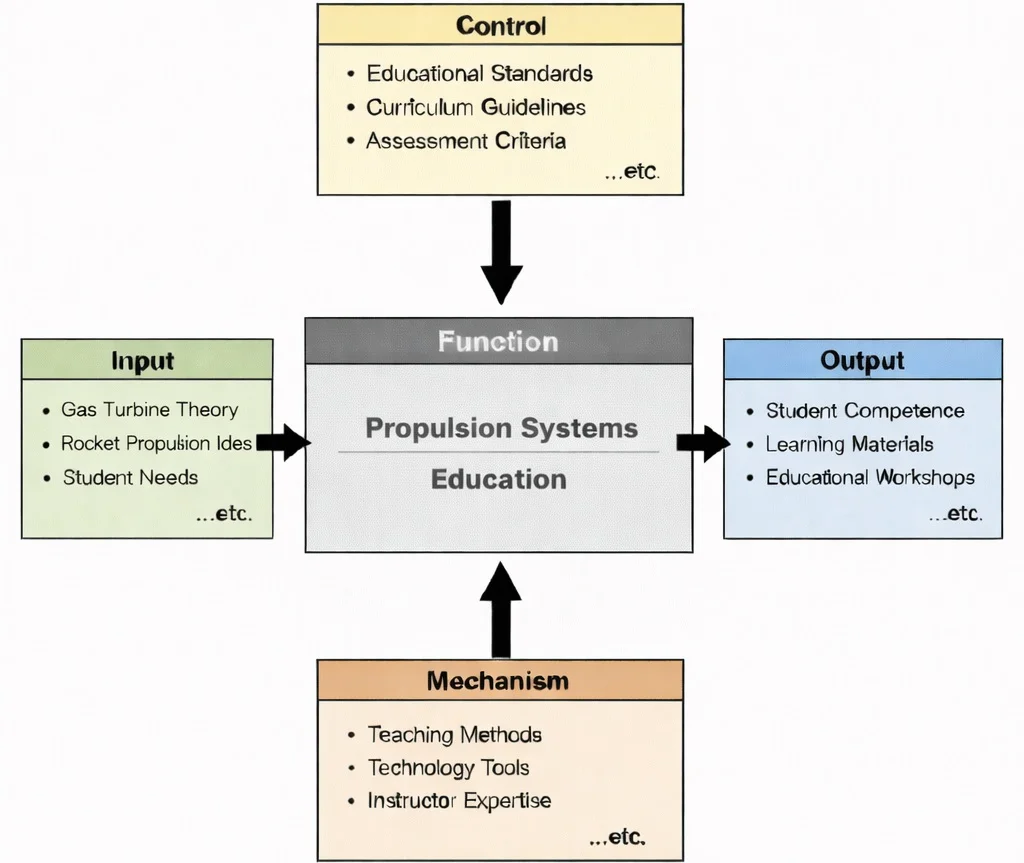
IDEF0 functional decomposition of Propulsion Systems Education: thermodynamic cycles and chemical reaction inputs governed by airworthiness and spaceflight standards, translated via hardware-in-the-loop test cells and cycle simulation mechanisms into certified thrust design and sizing competencies.

Aerospace Propulsion Systems: resolving the thermodynamic Brayton cycle and rocket momentum balance equations across compression, combustion, and high-enthalpy nozzle expansion.
This image presents a highly detailed jet engine in cutaway view, revealing the layered components that make propulsion possible—front fan and compressor stages, combustion region, turbine sections, and the surrounding network of fuel lines, sensors, and control hardware. The blueprint-style background and small rocket elements suggest the wider propulsion landscape, from turbofan and turbojet engines to rocket systems. Overall, the illustration emphasizes propulsion as an integrated engineering discipline that combines thermodynamics, fluid mechanics, combustion, materials, and control systems to generate thrust efficiently and safely.
Energy Conversion and Thrust Control Systems
Aerospace & Aeronautical – Overview
Integrates propulsion within the broader architecture of systems governing motion, atmospheric vehicle design, and spaceflight mechanics.
Propulsion Systems (Current Module)
Converts chemical, electrical, or thermal energy into controlled reaction thrust for atmospheric and space vehicles.
Celestial Mechanics
Determines how deliberate thrust impulses (Δv) reshape orbital trajectories, transfer orbits, and deep-space missions.
Flight Mechanics
Translates dynamic thrust vectoring into changes in velocity, rate of climb, acceleration, and maneuvering envelopes.
Aerodynamics
Governs external airflow behavior and aerodynamic drag that propulsion systems must overcome during atmospheric flight.
Hypersonics & High-Speed Aerodynamics
Introduces supersonic combustion, shock interactions, and extreme aerothermal heating constraints on engine inlets.
Aero Materials Science
Evaluates single-crystal superalloys and ceramic matrix composites under extreme combustion heat and mechanical stress.
Aerospace Structures
Designs engine mounts, nacelles, and thrust-bearing structures to endure high dynamic thrust and vibrational loading.
Aero Control Systems & Robotics
Controls FADEC algorithms, throttle responses, and gimballed thrust vector actuators for stability and guidance.
Avionics
Monitors real-time engine telemetry, turbine pressure ratios, fuel consumption rates, and health diagnostics.
Spacecraft Engineering
Integrates liquid rocket engines and RCS thrusters into interplanetary probes and crewed vehicles.
Satellite Technology
Utilizes electric propulsion, Hall-effect thrusters, and cold gas systems for precise orbital station-keeping.
Core Principles of Propulsion
Thrust Generation
A modern high-bypass geared commercial turbofan cruises at altitude where ambient pressure is \(P_a = 23.8 \text{ kPa}\) at true airspeed \(V_0 = 240.0 \text{ m/s}\). Calculate the total net thrust \(F_{\text{net}}\), the core-to-bypass thrust breakdown, and the thrust-specific fuel consumption (\(\text{TSFC}\)) given the following measured test cell cycle parameters:
- Total inlet air mass flow: \(\dot{m}_0 = 450.0 \text{ kg/s}\)
- Bypass Ratio (\(\text{BPR}\)): \(10.0 : 1.0\) (\(\dot{m}_{\text{bypass}} = 10 \cdot \dot{m}_{\text{core}}\))
- Fuel mass flow rate into combustor: \(\dot{m}_f = 1.80 \text{ kg/s}\)
- Bypass duct fan exit velocity: \(v_{e,\text{bypass}} = 340.0 \text{ m/s}\) (fully expanded: \(P_{e,\text{bypass}} = P_a\))
- Core nozzle exit velocity: \(v_{e,\text{core}} = 480.0 \text{ m/s}\) (fully expanded: \(P_{e,\text{core}} = P_a\))
Sequential Derivation & Calculation:
Step 1: Partition total mass flow into core and bypass streams:
$$\dot{m}_{\text{core}} = \frac{\dot{m}_0}{1 + \text{BPR}} = \frac{450.0 \text{ kg/s}}{1 + 10.0} = \frac{450.0}{11.0} = \mathbf{40.91 \text{ kg/s}}$$ $$\dot{m}_{\text{bypass}} = \dot{m}_0 - \dot{m}_{\text{core}} = 450.0 - 40.91 = \mathbf{409.09 \text{ kg/s}}$$Step 2: Calculate bypass stream net thrust contribution \(F_{\text{bypass}}\):
$$F_{\text{bypass}} = \dot{m}_{\text{bypass}} (v_{e,\text{bypass}} - V_0) = 409.09 \text{ kg/s} \times (340.0 \text{ m/s} - 240.0 \text{ m/s}) = 409.09 \times 100.0 = \mathbf{40,909 \text{ N}} \quad (\mathbf{40.91 \text{ kN}})$$Step 3: Calculate core stream net thrust contribution \(F_{\text{core}}\) (accounting for burned fuel mass \(\dot{m}_{\text{core}} + \dot{m}_f\)):
$$F_{\text{core}} = (\dot{m}_{\text{core}} + \dot{m}_f) v_{e,\text{core}} - \dot{m}_{\text{core}} V_0 = (40.91 + 1.80) \times 480.0 - (40.91 \times 240.0)$$ $$F_{\text{core}} = (42.71 \times 480.0) - (40.91 \times 240.0) = 20,500.8 - 9,818.4 = \mathbf{10,682.4 \text{ N}} \quad (\mathbf{10.68 \text{ kN}})$$Step 4: Evaluate total net engine thrust \(F_{\text{net}}\):
$$F_{\text{net}} = F_{\text{bypass}} + F_{\text{core}} = 40,909.0 \text{ N} + 10,682.4 \text{ N} = \mathbf{51,591.4 \text{ N}} \quad (\mathbf{51.59 \text{ kN}})$$Step 5: Compute the cruise Thrust-Specific Fuel Consumption (\(\text{TSFC}\)):
$$\text{TSFC} = \frac{\dot{m}_f}{F_{\text{net}}} = \frac{1.80 \text{ kg/s}}{51,591.4 \text{ N}} = 3.4889 \times 10^{-5} \text{ kg}/(\text{N}\cdot\text{s}) = \mathbf{12.56 \text{ g}/(\text{kN}\cdot\text{s})} \quad (0.443 \text{ lbm}/(\text{lbf}\cdot\text{hr}))$$Thermodynamic Cycle Insight: Notice that the bypass stream generates \(79.3\%\) of total vehicle thrust (\(40.91 \text{ kN} / 51.59 \text{ kN}\)). Imparting a modest velocity increment (\(\Delta v = 100 \text{ m/s}\)) across a massive cold bypass air stream maximizes Froude propulsive efficiency (\(\eta_p = \frac{2 V_0}{V_0 + v_e} \approx 82.8\%\)), minimizing wasteful kinetic energy dissipation in the downstream exhaust plume.
Contemporary AI-Era Computational Paradigms in Propulsion Systems
Consider a solid or scramjet combustor duct carrying constant cross-sectional area flow where heat addition \(q\) drives Mach number toward unity. The inlet Mach number is \(M_1 = 0.35\), inlet stagnation temperature is \(T_{01} = 650.0 \text{ K}\), and ratio of specific heats is \(\gamma = 1.33\). Calculate the maximum allowable heat addition \(q_{\text{max}}\) per unit mass before thermal choking occurs (\(M_2 = 1.0\)):
$$\frac{T_{01}}{T_0^*} = \frac{2(\gamma + 1) M_1^2 \left( 1 + \frac{\gamma - 1}{2} M_1^2 \right)}{(1 + \gamma M_1^2)^2}$$Step 1: Compute numerator terms with \(\gamma = 1.33\) and \(M_1 = 0.35\) (\(M_1^2 = 0.1225\)):
$$2(\gamma + 1) M_1^2 = 2 \times 2.33 \times 0.1225 = 4.66 \times 0.1225 = 0.57085$$ $$1 + \frac{\gamma - 1}{2} M_1^2 = 1 + \left(\frac{0.33}{2}\right) \times 0.1225 = 1 + (0.165 \times 0.1225) = 1 + 0.02021 = 1.02021$$ $$\text{Numerator} = 0.57085 \times 1.02021 = 0.58239$$Step 2: Compute denominator \((1 + \gamma M_1^2)^2\):
$$1 + \gamma M_1^2 = 1 + (1.33 \times 0.1225) = 1 + 0.162925 = 1.162925$$ $$(1.162925)^2 = 1.3524$$Step 3: Calculate stagnation temperature ratio and sonic choking temperature \(T_0^*\):
$$\frac{T_{01}}{T_0^*} = \frac{0.58239}{1.3524} = 0.43063 \Rightarrow T_0^* = \frac{T_{01}}{0.43063} = \frac{650.0 \text{ K}}{0.43063} = \mathbf{1,509.4 \text{ K}}$$Step 4: Compute critical maximum heat addition \(q_{\text{max}} = c_p (T_0^* - T_{01})\) with \(c_p = 1,150 \text{ J}/(\text{kg}\cdot\text{K})\):
$$q_{\text{max}} = 1,150 \text{ J}/(\text{kg}\cdot\text{K}) \times (1,509.4 \text{ K} - 650.0 \text{ K}) = 1,150 \times 859.4 = \mathbf{988,310 \text{ J/kg}} = \mathbf{988.31 \text{ kJ/kg}}$$Physical Implication: Injecting heat in excess of \(988.31 \text{ kJ/kg}\) into this duct forces an upstream normal shock wave to develop, reducing inlet flow velocity and dropping engine mass flow rate—a critical operational boundary in afterburner and scramjet combustor design.
Engineering Trade-offs in Aerospace Propulsion
| Propulsion System Trade-off | Primary Performance Benefit | Systemic Penalty / Risk | Quantitative Design Metric |
|---|---|---|---|
| Ultra-High Bypass Ratio (\(\text{BPR} > 12\)) vs. Nacelle Drag | Maximizes propulsive efficiency (\(\eta_p \ge 85\%\)); slashes specific fuel consumption and airport noise footprint. | Massive fan diameter requires longer landing gear, introduces high nacelle wetted area drag, and increases engine weight. | Bypass Ratio (\(\text{BPR}\)): Older Jets (\(4\text{--}6\)); Modern Geared Turbofans (\(11\text{--}14\)); Open Rotor (\(>30\)). |
| Turbine Inlet Temperature (\(T_{\text{IT}}\)) vs. Blade Creep Life | Higher \(T_{\text{IT}}\) increases thermal cycle efficiency (\(\eta_{\text{th}}\)) and specific core thrust per kilogram of air. | Demands bleeding up to 20% of compressor air for internal cooling; accelerates thermal fatigue and superalloy oxidation. | Turbine Inflow Temp: Military Combat (\(1,800\text{--}2,000 \text{ K}\)); Commercial Cruise (\(1,500\text{--}1,700 \text{ K}\)). |
| Chemical Rocket vs. Electric Hall-Effect Thruster | Chemical engines deliver massive thrust-to-weight (\(T/W > 70\)), essential for escaping Earth's gravitational well. | Low specific impulse (\(I_{\text{sp}} \approx 300\text{--}450 \text{ s}\)); consumes massive propellant fractions for small \(\Delta v\). | Specific Impulse: Hydrolox Rocket (\(I_{\text{sp}} \approx 450 \text{ s}\)); Xenon Hall Thruster (\(I_{\text{sp}} \approx 1,800\text{--}3,200 \text{ s}\)). |
| Liquid Staged-Combustion vs. Gas-Generator Cycle | Routes preburner exhaust through the main chamber, eliminating turbine dump losses and raising chamber pressure (\(P_c > 200 \text{ bar}\)). | Extremely high turbopump discharge pressures (\(>400 \text{ bar}\)), severe seal wear, and complex ignition timing. | Chamber Pressure (\(P_c\)): Gas Generator (\(70\text{--}100 \text{ bar}\)); Full-Flow Staged (\(250\text{--}300 \text{ bar}\)). |
Consider a first-stage booster rocket operating at sea level (\(P_a = 101.3 \text{ kPa}\)). Sizing the nozzle with an aggressive vacuum expansion area ratio (\(\epsilon = A_e / A_t = 60\)) lowers nozzle exit pressure to \(P_e = 30.0 \text{ kPa}\). Because \(P_e < 0.40 P_a\), the severe adverse external pressure forces the boundary layer to detach inside the nozzle bell, generating destructive asymmetric shock separation (Summerfield criterion) and negative pressure thrust:
$$\Delta F_{\text{pressure}} = (P_e - P_a) A_e = (30,000 \text{ Pa} - 101,325 \text{ Pa}) \times 1.20 \text{ m}^2 = \mathbf{-85,590 \text{ N}} \quad (\mathbf{-85.59 \text{ kN penalty}})$$Conclusion: First-stage boosters must restrict expansion ratio (\(\epsilon \approx 12\text{--}16\)) to prevent sea-level nozzle flow separation, while vacuum upper stages deploy large area ratios (\(\epsilon > 150\)) to extract maximum momentum from expanding exhaust gases.
Interactive Rocket Thrust & Delta-v Simulator
Interactive Spacecraft Thrust & Delta-v Curve Simulator
Adjust engine parameters below to simulate real-time velocity gain (Δv) over the burn duration according to Tsiolkovsky's Rocket Equation: Δv = Isp × g0 × ln(m0 / m(t)).
Interactive runtime environment: https://prep4uni.online/stem/physical-technologies/aerospace-and-aeronautical-engineering/propulsion-systems/
Types of Propulsion Systems
Jet Engines
- Turbojet Engines: Straight airflow path where all ingested air passes through the core compressor, combustion chamber, and turbine. Effective for high-supersonic interceptors but thermally inefficient at subsonic cruise speeds.
- Turbofan Engines: Front fan accelerates large quantities of secondary bypass air around the core engine, achieving superior propulsive efficiency and low noise for commercial aviation.
- Turboprop Engines: Gas turbine drives a reduction gearbox and propeller, delivering optimal fuel efficiency for low-speed, regional short-haul transport aircraft.
- Ramjets: Lacks rotating turbomachinery, utilizing forward supersonic flight speed to shock-compress incoming air prior to combustion; requires a booster to reach operational speeds (\(M > 2.5\)).
- Scramjets (Supersonic Combustion Ramjets): Operates with supersonic flow throughout the entire combustion chamber (\(M_{\text{internal}} > 1.0\)), designed for hypersonic cruise regimes above Mach 5.
Rocket Engines
- Liquid-Fueled Rockets: Cryogenic or hypergolic propellants pumped into a thrust chamber at high pressures; offers throttling, shutdown, and restart capabilities.
- Solid-Fueled Rockets: Cast propellant grain combining oxidizer and fuel in a simple, highly reliable casing; provides high initial thrust for launch vehicle strap-on boosters.
- Hybrid Rockets: Combines solid fuel grains with liquid or gaseous oxidizers, offering mechanical throttling with reduced handling risks.
Electric Propulsion Systems
- Gridded Ion Thrusters: Electrostatic extraction grids accelerate xenon ions to exhaust velocities of \(30\text{--}50 \text{ km/s}\), delivering specific impulse values exceeding \(3,000 \text{ s}\).
- Hall-Effect Thrusters: Cross-field magnetic electron traps ionize xenon or krypton, balancing specific impulse (\(1,500\text{--}2,000 \text{ s}\)) with higher thrust density for satellite orbital transfers.
- Pulsed Plasma Thrusters (PPT): Electromagnetic acceleration of ablated Teflon solid propellant pulses, ideal for precise CubeSat attitude control.
Green Propulsion Technologies
- Sustainable Aviation Fuels (SAF): Hydroprocessed esters and fatty acids (HEFA) and synthetic kerosene providing 100% drop-in hydrocarbon compatibility with up to 80% lifecycle carbon reduction.
- Cryogenic Hydrogen Propulsion: High gravimetric energy density (\(120 \text{ MJ/kg}\) vs. \(43 \text{ MJ/kg}\) for Jet-A) producing zero in-flight \(\text{CO}_2\) emissions.
- Distributed Electric Propulsion (DEP): Arrays of wing-integrated electric fans powered by central fuel cells or hybrid turbo-generators, blowing air across wing upper surfaces to augment high-lift coefficients.
Design and Optimization Considerations in Propulsion Systems
Efficiency
Reliability and Safety
Materials Science
Thermal Management
Why Study Propulsion Systems
Fundamentals of Thrust Generation
Thermodynamics and Fluid Mechanics
Design and Performance Optimization
Environmental and Noise Considerations
Propulsion in Diverse Applications
Propulsion Systems: Conclusion
Interactive Self-Assessment: Key Propulsion Concepts
Self-Check 1: Why does higher bypass ratio improve efficiency in commercial turbofans?
Self-Check 2: What prevents chemical rockets from achieving the high specific impulse of electric thrusters?
Frequently Asked Questions on Aerospace Propulsion Systems
These FAQs connect basic propulsion concepts to the bigger picture of aircraft and spacecraft design, fuel efficiency, and future technologies.
What does a “propulsion system” actually do in an aircraft or spacecraft?
A propulsion system provides the thrust needed to overcome drag and gravity so that a vehicle can accelerate, climb, cruise, or manoeuvre. In aircraft this usually means an air-breathing engine that accelerates air backwards; in spacecraft it typically means a rocket that expels high-speed exhaust gases. Without propulsion, the airframe or spacecraft structure cannot perform any useful mission.
How do air-breathing engines differ from rocket engines?
Air-breathing engines, such as turbojets and turbofans, take in oxygen from the atmosphere to burn fuel, so they only need to carry fuel on board. Rockets carry both fuel and oxidiser, allowing them to operate in space where there is no air. The trade-off is that rockets are simpler in principle but must lift all their propellant, while air-breathing engines are more efficient within the atmosphere.
Why are turbofan engines used on most modern passenger aircraft?
Turbofan engines use a large fan to accelerate a big mass of air at a moderate speed, which is more fuel-efficient and quieter than accelerating a small mass of air to very high speed, as in a pure turbojet. This high-bypass design gives better specific fuel consumption, lower noise, and good performance at typical airliner cruise speeds and altitudes.
What is “specific impulse” in simple terms?
Specific impulse is a measure of how efficiently a propulsion system uses its propellant. Informally, it tells you how much “thrust per unit of propellant flow” you get. A higher specific impulse means the engine can generate the same thrust while using less propellant, which is especially important for rockets and electric propulsion where every kilogram of propellant matters.
How can rockets work in space when there is no air to push against?
Rockets do not need air to push against; they work by expelling mass at high speed in one direction and experiencing an equal and opposite reaction, as described by Newton’s third law. The expanding exhaust gases push on the inside of the nozzle, generating thrust even in a vacuum. This is why rockets are the main choice for launch vehicles and deep-space missions.
Where does electric propulsion fit into modern space missions?
Electric propulsion systems use electrical power—often from solar panels—to accelerate ions or plasma to very high exhaust velocities. The thrust is small but extremely efficient, giving very high specific impulse. As a result, electric propulsion is widely used for satellite station-keeping and deep-space probes, where long-duration, low-thrust acceleration is acceptable.
How is propulsion linked to environmental sustainability in aviation?
Propulsion strongly influences fuel burn, emissions, and noise. Modern engine designs aim to reduce CO2 and NOx emissions through higher efficiency, improved aerodynamics, and alternative fuels. Research into hybrid-electric propulsion, sustainable aviation fuels, and more efficient turbofan architectures reflects the wider push to make air transport cleaner and quieter.
What should students focus on when first learning about propulsion systems?
Students should first understand basic ideas: thrust, mass flow, Newton’s laws, and the differences between air-breathing and rocket propulsion. From there, they can explore specific engine types, such as turbojet, turbofan, rocket, and electric propulsion; how performance is measured, including thrust, specific impulse, and efficiency; and how design choices are shaped by mission requirements such as speed, altitude, or operating environment.
Comprehensive Practice & Assessment Module
Section 1: Foundational Review Questions
1. What is the primary function of a propulsion system in aerospace engineering?
2. Name two main types of air-breathing engines used in aircraft.
3. How does a turbojet engine produce thrust?
4. What distinguishes a turbofan engine from a turbojet engine?
5. What type of propulsion system is commonly used for spacecraft?
6. Explain the basic principle of rocket propulsion.
7. What is specific impulse, and why is it important in evaluating propulsion systems?
8. What are the main components of a typical liquid rocket engine?
9. How do solid rocket motors differ from liquid rocket engines?
10. What is electric propulsion, and in what applications is it commonly used?
Section 2: Analytical & Scenario-Based Questions
1. How might advancements in propulsion systems impact the future of commercial air travel?
2. What are the environmental implications of current propulsion technologies, and how can engineers mitigate negative impacts?
3. In what ways do propulsion requirements differ between atmospheric flight and space travel?
4. How do engineers balance the trade-offs between thrust and fuel efficiency in propulsion system design?
5. What challenges do hypersonic speeds present to propulsion systems, and what solutions are being explored?
6. How does the choice between solid and liquid propellants affect rocket design and performance?
7. What role does computational fluid dynamics, CFD, play in the development of propulsion systems?
8. How are alternative fuels influencing the future design of propulsion systems?
9. What are the key considerations in designing propulsion systems for reusable launch vehicles?
Section 3: Mathematical & Calculation Problems
1. Net Thrust Generated by a Turbojet Engine
Problem: Calculate the net thrust generated by a jet engine with air mass flow rate \(\dot{m} = 50.0 \text{ kg/s}\), exit exhaust jet velocity \(v_e = 600.0 \text{ m/s}\), and flight speed \(v_0 = 250.0 \text{ m/s}\) (assuming fully expanded nozzle flow \(P_e = P_a\)).
Answer:
Step 1: State the net momentum thrust equation:
\(F_{\text{net}} = \dot{m} (v_e - v_0)\)
Step 2: Evaluate the velocity increment across the engine:
\(\Delta v = v_e - v_0 = 600.0 \text{ m/s} - 250.0 \text{ m/s} = 350.0 \text{ m/s}\)
Step 3: Calculate net thrust in Newtons:
\(F_{\text{net}} = 50.0 \text{ kg/s} \times 350.0 \text{ m/s} = \mathbf{17,500.0 \text{ N}}\)
Step 4: Convert to kilonewtons:
\(F_{\text{net}} = \frac{17,500.0 \text{ N}}{1,000} = \mathbf{17.50 \text{ kN}}\)
The total net thrust produced by the turbojet engine is 17.50 kN.
2. Rocket Effective Exhaust Velocity and Specific Impulse
Problem: A liquid rocket engine burns propellant at rate \(\dot{m} = 120.0 \text{ kg/s}\) and generates total vacuum thrust \(F = 360,000.0 \text{ N}\). Calculate effective exhaust velocity \(c\) and specific impulse \(I_{\text{sp}}\) (using \(g_0 = 9.81 \text{ m/s}^2\)).
Answer:
Step 1: Calculate effective exhaust velocity \(c\):
\(c = \frac{F}{\dot{m}} = \frac{360,000.0 \text{ N}}{120.0 \text{ kg/s}} = \mathbf{3,000.0 \text{ m/s}} \quad (3.00 \text{ km/s})\)
Step 2: Calculate specific impulse \(I_{\text{sp}}\):
\(I_{\text{sp}} = \frac{c}{g_0} = \frac{3,000.0 \text{ m/s}}{9.81 \text{ m/s}^2} = \mathbf{305.81 \text{ s}}\)
The rocket effective exhaust velocity is 3,000.0 m/s and specific impulse is 305.81 seconds.
3. Spacecraft Velocity Gain via Tsiolkovsky's Rocket Equation
Problem: An exploratory probe with initial mass \(m_0 = 1,200.0 \text{ kg}\) and dry mass \(m_f = 400.0 \text{ kg}\) utilizes an ion thruster with specific impulse \(I_{\text{sp}} = 3,000.0 \text{ s}\). Calculate total mission velocity gain (\(\Delta v\)).
Answer:
Step 1: State Tsiolkovsky's rocket equation:
\(\Delta v = I_{\text{sp}} \cdot g_0 \cdot \ln\left(\frac{m_0}{m_f}\right)\)
Step 2: Calculate mass ratio and its natural logarithm:
\(\frac{m_0}{m_f} = \frac{1,200.0 \text{ kg}}{400.0 \text{ kg}} = 3.000\)
\(\ln(3.000) = 1.09861\)
Step 3: Compute velocity increment:
\(\Delta v = 3,000.0 \text{ s} \times 9.81 \text{ m/s}^2 \times 1.09861 = 29,430.0 \times 1.09861 = \mathbf{32,332.1 \text{ m/s}}\)
Step 4: Convert to kilometers per second:
\(\Delta v = \frac{32,332.1 \text{ m/s}}{1,000} = \mathbf{32.33 \text{ km/s}}\)
The total velocity gain achievable by the ion propulsion system is 32.33 km/s.
4. Turbofan Bypass Mass Flow Partitioning
Problem: A turbofan engine operates with bypass ratio \(\text{BPR} = 8.0 : 1.0\). If core mass flow rate is \(\dot{m}_{\text{core}} = 15.0 \text{ kg/s}\), calculate bypass duct mass flow \(\dot{m}_{\text{bypass}}\) and total ingested engine air mass flow \(\dot{m}_{\text{total}}\).
Answer:
Step 1: Apply bypass ratio definition (\(\text{BPR} = \frac{\dot{m}_{\text{bypass}}}{\dot{m}_{\text{core}}}\)):
\(\dot{m}_{\text{bypass}} = \text{BPR} \times \dot{m}_{\text{core}} = 8.0 \times 15.0 \text{ kg/s} = \mathbf{120.0 \text{ kg/s}}\)
Step 2: Calculate total mass flow rate:
\(\dot{m}_{\text{total}} = \dot{m}_{\text{core}} + \dot{m}_{\text{bypass}} = 15.0 \text{ kg/s} + 120.0 \text{ kg/s} = \mathbf{135.0 \text{ kg/s}}\)
The bypass stream mass flow is 120.0 kg/s and total inlet air mass flow is 135.0 kg/s.
5. Propellant Mass Fraction for Orbital Insertion
Problem: Determine the propellant mass fraction (\(\zeta = \frac{m_p}{m_0}\)) required for an orbital insertion burn with required \(\Delta v = 2,200.0 \text{ m/s}\) using an upper-stage engine with \(I_{\text{sp}} = 320.0 \text{ s}\).
Answer:
Step 1: Calculate the exponential velocity exponent:
\(\frac{\Delta v}{I_{\text{sp}} \cdot g_0} = \frac{2,200.0 \text{ m/s}}{320.0 \text{ s} \times 9.81 \text{ m/s}^2} = \frac{2,200.0}{3,139.2} = 0.700815\)
Step 2: Calculate initial-to-final mass ratio:
\(\frac{m_0}{m_f} = e^{0.700815} = 2.0154\)
Step 3: Solve for propellant mass fraction \(\zeta\):
\(\zeta = 1 - \frac{m_f}{m_0} = 1 - \frac{1}{2.0154} = 1 - 0.49618 = \mathbf{0.5038} \quad (\mathbf{50.38\%})\)
The vehicle must allocate 50.38% of its initial mass to propellant.
6. Inlet Ram Drag Force Calculation
Problem: An aircraft cruising at flight speed \(v_0 = 200.0 \text{ m/s}\) ingests ambient air at mass flow rate \(\dot{m} = 80.0 \text{ kg/s}\). Calculate the inlet ram drag force \(F_{\text{ram}}\) exerted on the engine cowls.
Answer:
Step 1: State the ram drag momentum equation:
\(F_{\text{ram}} = \dot{m} \cdot v_0\)
Step 2: Substitute values:
\(F_{\text{ram}} = 80.0 \text{ kg/s} \times 200.0 \text{ m/s} = \mathbf{16,000.0 \text{ N}}\)
Step 3: Convert to kilonewtons:
\(F_{\text{ram}} = \frac{16,000.0 \text{ N}}{1,000} = \mathbf{16.00 \text{ kN}}\)
The inlet ram drag force opposing forward motion is 16.00 kN.
7. Rocket Nozzle Pressure Thrust Imbalance Evaluation
Problem: A rocket nozzle has exit planform area \(A_e = 0.250 \text{ m}^2\) and nozzle exit static pressure \(P_e = 80.0 \text{ kPa}\). During ascent, ambient pressure drops to \(P_a = 20.0 \text{ kPa}\). Calculate the pressure thrust component \(F_{\text{pressure}}\) contributing to total thrust.
Answer:
Step 1: State the pressure thrust imbalance equation:
\(F_{\text{pressure}} = (P_e - P_a) A_e\)
Step 2: Convert pressure difference to Pascals (\(\text{N/m}^2\)):
\(P_e - P_a = 80.0 \text{ kPa} - 20.0 \text{ kPa} = 60.0 \text{ kPa} = 60,000.0 \text{ N/m}^2\)
Step 3: Multiply by nozzle exit area:
\(F_{\text{pressure}} = 60,000.0 \text{ N/m}^2 \times 0.250 \text{ m}^2 = \mathbf{15,000.0 \text{ N}}\)
Step 4: Convert to kilonewtons:
\(F_{\text{pressure}} = \frac{15,000.0 \text{ N}}{1,000} = \mathbf{15.00 \text{ kN}}\)
The nozzle pressure thrust contribution is 15.00 kN.