Prepare for University Studies & Career Advancement
Wave Optics
Wave optics, also called physical optics, studies light as a wave rather than only as a set of straight-line rays. This approach becomes essential whenever light overlaps, spreads, forms fringes, separates into colours, or reveals a direction of electric-field vibration. These effects cannot be fully explained by geometrical optics alone.
In geometrical optics, light is often treated as rays that reflect, refract, and form images. That model is powerful for mirrors, lenses, cameras, and many everyday optical systems. But when openings become small, surfaces become extremely thin, sources become coherent, or fine patterns become important, the ray model begins to hide the deeper behaviour. Wave optics restores that missing layer.
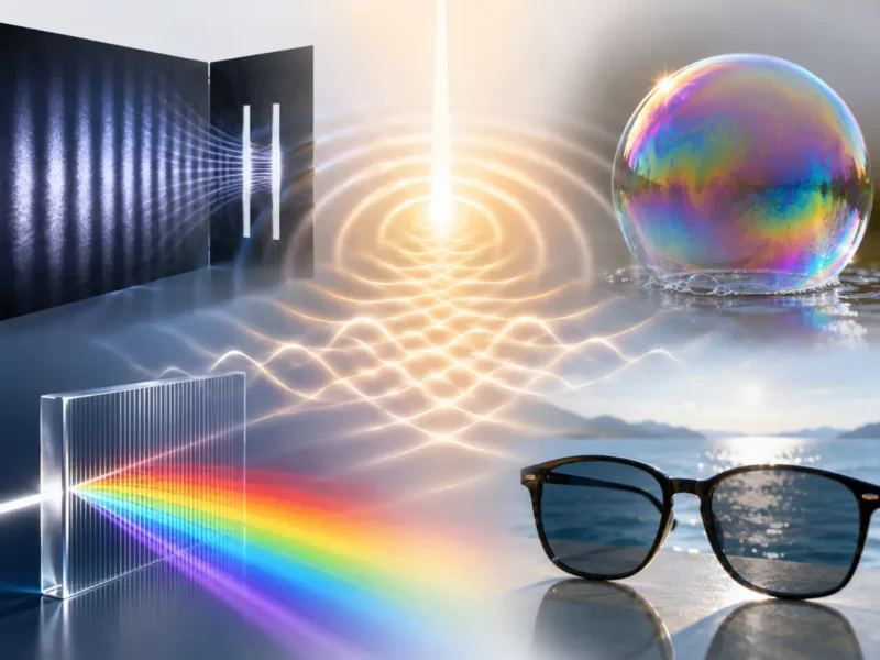
The central ideas of wave optics are superposition, phase, path difference, coherence, interference, diffraction, and polarization. Together, they explain why soap bubbles show colours, why telescopes have resolution limits, why diffraction gratings separate light precisely, why lasers produce stable interference patterns, and why polarizing sunglasses reduce glare.
This page serves as the master hub for the Wave Optics cluster within Light and Optics. It establishes a structured map across six dedicated subpages:
Explains how overlapping light waves produce bright and dark regions through constructive and destructive interference. This page is the natural starting point for understanding phase, path difference, Young’s double-slit experiment, and fringe formation.
Shows how reflections from two nearby surfaces create colours in soap bubbles, oil films, anti-reflection coatings, Newton’s rings, and wedge films. This page connects interference with real surfaces whose thickness is comparable to the wavelength of light.
Explains how light spreads around edges and through apertures, and why this spreading limits the sharpness of images. This page is central for understanding microscopes, telescopes, camera lenses, Airy patterns, and resolving power.
Shows how many regularly spaced slits or grooves separate light into precise directions. This page links diffraction and interference to spectroscopy, wavelength measurement, colour separation, and spectral analysis.
Explains why stable phase relationships are needed for clear interference and how interferometers use wave overlap to measure tiny distances, refractive index changes, surface quality, and optical path differences.
Explains how the electric field direction of light can be selected, rotated, analysed, or modified by polarizers, reflection, scattering, birefringent materials, optical activity, and wave plates.
Wave optics explains light as a wave, revealing effects such as interference, diffraction, colour separation, thin-film colours, and polarization.
What Wave Optics REALLY Means
Wave optics is not simply a more difficult version of ray optics. It is a different way of seeing light. Instead of asking only where a light ray goes, wave optics asks how the whole wavefront behaves, how different parts of a wave arrive with different phases, and how overlapping waves combine to produce visible patterns.
The word wave is important because light carries repeating electric and magnetic field oscillations. These oscillations have wavelength, frequency, phase, amplitude, and direction. When two light waves meet, their fields do not ignore each other. They add. Sometimes the result is stronger light. Sometimes the result is weaker light. Sometimes a whole pattern of bright and dark regions appears.
This is why wave optics often feels more surprising than geometrical optics. A narrow slit does not merely let light through; it makes light spread. Two slits do not simply produce two bright patches; they create many fringes. A transparent film does not merely reflect light; it may select colours. A polarizer does not merely darken light; it selects a direction of electric-field vibration.
Wave optics therefore teaches students to notice what is hidden inside ordinary seeing. Light is not only travelling. It is oscillating, overlapping, spreading, and carrying phase information.
The Evolutionary Path: History, System Barriers, and Foundry Paradigms
The systematic tracking of physical optics transitioned light physics from simple linear geometric path-tracing into a precise science of wavefront orchestration and field modulation.
The Historical Journey
The wave foundation of optics was established in 1678 when Christiaan Huygens proposed that every point on a advancing light front acts as a source of secondary spherical wavelets. This classical model gained definitive confirmation in 1801 through Thomas Young’s double-slit experiment, which proved that light waves undergo spatial interference. By 1819, Augustin-Jean Fresnel unified Huygens’ wavelets with the principle of mathematical superposition, successfully detailing how light diffracts around small obstructions. Physical optics transitioned into an exact field within electromagnetic theory during 1865, when James Clerk Maxwell’s unified equations proved that light travels through space as self-sustaining electric and magnetic field oscillations.
Contemporary Technical Hurdles
The primary barrier to engineering nanometer-scale wave interfaces is managing **phase decorrelation and scattering parameters**. When a coherent laser front hits an un-optimized surface boundary, structural irregularities cause localized phase variations. This randomness mixes up the relative wave paths, breaking down stable interference conditions and transforming clean focal points into chaotic laser speckle noise. Furthermore, standard lithography platforms struggle with diffraction boundaries, as light passing through ultra-fine stencil lines spreads out automatically, limiting how small a processor circuit track can be printed on a silicon wafer substrate.
Future Paradigms: Metasurfaces and Sub-Wavelength Lithography
Modern semiconductor foundries bypass classical wave boundaries by deploying pattern-etched sub-wavelength arrays and high-frequency extreme ultraviolet sources:
Planar Nanostructured Metasurfaces: To alter wavefront parameters without relying on bulky curved glass, optical foundries are pattern-etching flat sub-wavelength arrays of silicon or titanium dioxide pillars. These nano-antennas introduce precise phase shifts across local coordinate paths, enabling flat, micron-thin lenses that manipulate focal length, polarization tracks, and color dispersion loops simultaneously.
Extreme Ultraviolet (EUV) Printing Tracks: To circumvent diffraction-limited resolution boundaries in advanced lithography tracks, manufacturing cleanrooms deploy EUV light systems operating near a 13.5 nm wavelength window. Because this short wavelength experiences minimal wave-spreading compared to standard ultraviolet systems, laser arrays can etch transistor paths below the 3 nm boundary without triggering diffraction blur.
Learning Pathway
The Wave Optics cluster is organised as a learning pathway. Students begin with interference, where overlapping waves produce bright and dark regions. They then meet thin-film interference, where tiny thickness differences create colours. Diffraction and resolution explain why wave spreading limits image sharpness. Diffraction gratings show how many regularly spaced grooves or slits separate wavelengths precisely. Coherence and interferometry show how stable phase relationships support precision measurement. Polarization adds the directional nature of the electric field.
Explores how light travels, reflects, refracts, diffracts, interferes, forms images, and interacts with materials.
Wave Optics
Treats light as a wave and explains interference, diffraction, coherence, polarization, and wave-based optical effects.
Core Ideas Students Should Understand
Although the subtopics in wave optics may look separate, they are built from a small number of recurring ideas. Once these ideas become familiar, the whole cluster becomes easier to connect.
Light Has Wavelength
Wavelength is the distance over which a light wave repeats. Visible wavelengths are very small, typically hundreds of nanometres. This small scale explains why wave effects are sometimes hidden in everyday life but become obvious near narrow slits, fine grooves, thin films, small apertures, and precise optical instruments.
The basic wave relation is:
$$v = f\lambda$$
For light in vacuum, this is usually written as:
$$c = f\lambda$$
Here, c is the speed of light in vacuum, f is frequency, and λ is wavelength. In a material, the speed and wavelength change, while the frequency remains fixed across a boundary.
Phase Determines How Waves Combine
Phase describes where a wave is in its cycle. Two waves may have the same wavelength and travel to the same place, but if one arrives crest-to-crest with the other, the result is different from one arriving crest-to-trough.
When waves arrive in step, they reinforce and produce constructive interference. When they arrive out of step, they weaken or cancel and produce destructive interference. Many wave-optics patterns are really maps of phase difference across space.
Path Difference Creates Phase Difference
A path difference occurs when two waves travel different distances before meeting. If the difference is a whole number of wavelengths, constructive interference may occur. If it is an odd half-number of wavelengths, destructive interference may occur.
This idea appears repeatedly: in double-slit interference, thin films, diffraction gratings, interferometers, and many optical measurement systems. A small distance difference can become visible because light wavelengths are so small.
Superposition Explains Fringe Patterns
Superposition means that when waves overlap, their displacements or fields add. This does not mean the waves permanently destroy one another. It means the observed result at a point depends on the combined field at that point.
Bright and dark fringes are not painted onto space. They are produced by many waves arriving with different phase relationships. Where reinforcement is repeated regularly, a stable pattern appears.
Coherence Makes Interference Stable
Coherence describes how stable the phase relationship is between waves. Without sufficient coherence, interference effects may blur or average out. With good coherence, wave patterns can remain sharp enough to measure.
This is why lasers are so useful in wave optics. Their light can have strong coherence, making them suitable for interferometry, holography, precision alignment, and scientific measurement.
Diffraction Shows That Light Spreads
Diffraction occurs when light passes through an aperture or around an edge and spreads into regions that simple ray optics would not predict. The effect becomes especially important when the aperture size is comparable to the wavelength.
Diffraction is not a minor imperfection. It is a fundamental wave behaviour. It explains why optical images cannot be made infinitely sharp by using perfect lenses alone.
Polarization Shows That Light Is Transverse
Polarization describes the direction of the electric field vibration in light. It is possible because light is a transverse electromagnetic wave. The electric field vibrates perpendicular to the direction of travel, and this direction can be selected or modified.
Polarization is therefore not only a practical tool for sunglasses and displays. It is also evidence for the geometry of electromagnetic waves.
Wave optics is built from a small set of connected ideas: wavelength, phase, path difference, superposition, coherence, diffraction, and polarization.
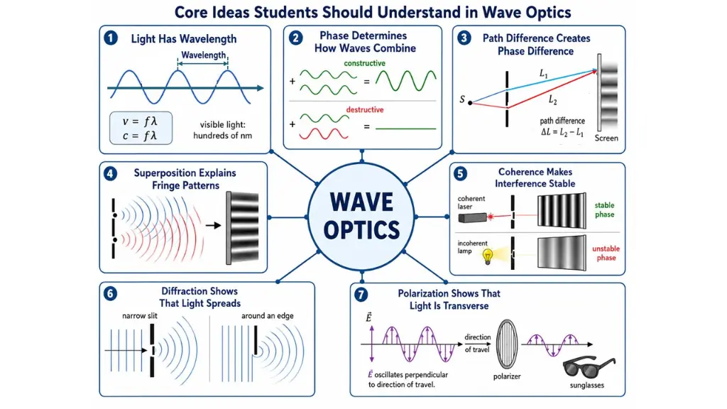
This infographic summarises the core ideas students need for understanding wave optics. It shows that light has wavelength, that phase determines how waves combine, and that path difference creates phase difference. It also illustrates how superposition produces fringe patterns, how coherence makes interference stable, how diffraction causes light to spread near slits and edges, and how polarization reveals that light is a transverse electromagnetic wave. Together, these ideas connect the major topics in the Wave Optics cluster, including interference, thin-film interference, diffraction and resolution, diffraction gratings, coherence and interferometry, and polarization of light.
Wave Optics Versus Geometrical Optics
Geometrical optics and wave optics are not enemies. They are two levels of description. Ray optics is often sufficient when objects, openings, and surfaces are much larger than the wavelength of light. Wave optics becomes necessary when wavelength, phase, and interference affect what is observed.
Aspect
Geometrical Optics
Wave Optics
Main model
Light is treated as rays.
Light is treated as waves with phase and wavelength.
Best for
Mirrors, lenses, image formation, ray tracing, and large-scale optical paths.
Interference, diffraction, polarization, coherence, thin films, and resolution limits.
Cannot fully explain fringes, diffraction spreading, polarization, or wavelength-scale effects.
More detailed and sometimes mathematically heavier, especially for complex systems.
How the Six Subtopics Connect
The six subpages are best understood as a connected sequence rather than isolated lessons. Each one extends the meaning of light as a wave.
Interference of Light: Waves Add
Interference of Light introduces the central idea that overlapping light waves can reinforce or cancel. This page explains phase difference, path difference, bright fringes, dark fringes, and the importance of coherent sources.
It is the foundation for much of wave optics because thin films, gratings, interferometers, and many natural colour effects depend on interference.
Thin-Film Interference shows how light reflected from two nearby surfaces can interfere. A soap bubble, oil film, or optical coating may be nearly transparent, but its small thickness can select certain wavelengths for reinforcement or cancellation.
This topic helps students see that interference is not limited to laboratory slits. It appears in everyday colours and engineered coatings.
Diffraction and Resolution: Waves Spread and Images Have Limits
Diffraction and Resolution explains why light spreads after passing through openings and why this affects image sharpness. Even with a perfect lens, diffraction limits how close two points can be before they blur together.
This topic is essential for understanding microscopes, telescopes, cameras, imaging sensors, and the physical limits of observation.
Diffraction Gratings applies interference and diffraction to many repeated slits or grooves. The result is sharper and more precise wavelength separation than simple dispersion in many contexts.
Gratings are important in spectrometers, astronomy, chemistry, laser systems, optical communication, and wavelength measurement.
Coherence and Interferometry: Stable Waves Measure Tiny Changes
Coherence and Interferometry explains why stable phase relationships matter. Interferometers use interference patterns to detect tiny changes in distance, refractive index, surface shape, and optical path length.
This topic shows how wave optics becomes a precision measurement tool, not merely a visual phenomenon.
Polarization of Light: Waves Have Direction
Polarization of Light focuses on the orientation of the electric field. It explains polarizers, analysers, Malus’s law, reflection glare, scattering, birefringence, optical activity, and wave plates.
Polarization completes the wave-optics picture by showing that light is not only a scalar brightness wave. It has directional electromagnetic structure.
Modern Relevance of Wave Optics
Wave optics is not only a historical chapter in physics. It sits underneath many modern technologies that depend on controlling light with high precision.
Imaging and Resolution
Microscopes, telescopes, cameras, lithography systems, and medical imaging tools all face wave-based resolution limits. Understanding diffraction helps explain why better imaging is not only a matter of stronger lenses.
Optical Coatings
Anti-reflection coatings, high-reflection mirrors, filters, and display layers use thin-film interference to control which wavelengths are reflected, transmitted, strengthened, or suppressed.
Spectroscopy
Diffraction gratings and interference-based instruments separate light by wavelength, helping scientists identify atoms, molecules, stars, gases, materials, and chemical compositions.
Precision Measurement
Interferometry can measure extremely small changes in distance, surface shape, refractive index, and vibration. These methods are used in laboratories, engineering, optics manufacturing, and advanced sensing.
Displays and Polarization Control
Polarization is central to liquid crystal displays, optical modulators, polarizing filters, stress analysis, and many instruments that control or analyse the electric-field direction of light.
Photonics and Communication
Wave behaviour supports photonics, fiber optics, laser systems, optical sensors, and communication technologies that use light to transmit, process, or measure information.
Connections with Other Light and Optics Topics
Wave optics connects naturally with other areas of Light and Optics. It does not replace them; it deepens them.
Provides the ray model for reflection, refraction, mirrors, lenses, and image formation. Wave optics explains where the ray model begins to lose accuracy.
Explores how light interacts with droplets, aerosols, ice crystals, and the atmosphere, producing effects related to scattering, interference, diffraction, and polarization.
Studies situations where intense light changes the optical response of materials, leading to frequency conversion, self-focusing, and other advanced effects.
Wave Optics and Electromagnetic Theory
Wave optics becomes more meaningful when connected with electricity and magnetism. Light is an electromagnetic wave, so its wave behaviour is not only a pattern on a screen. It is the behaviour of electric and magnetic fields travelling through space or materials.
The study of electromagnetic waves helps students understand why light can be polarized, why it carries energy and momentum, and why its speed changes in media. The deeper framework of electrodynamics explains how changing electric and magnetic fields sustain wave propagation.
This connection also explains why wave optics appears across many wavelength ranges. The same broad ideas apply not only to visible light, but also to radio waves, microwaves, infrared radiation, ultraviolet radiation, X-rays, and other electromagnetic waves.
Wave Optics and Modern Physics
Wave optics also prepares students for modern physics. The interference of light was historically one of the strongest arguments for the wave nature of light, yet modern experiments also show that light is detected in discrete packets called photons.
This does not make wave optics obsolete. Instead, it makes wave optics part of a deeper story. Quantum optics uses probability amplitudes, photon interference, and quantum states to extend classical wave ideas. The classical wave patterns remain essential, but their interpretation becomes richer at the quantum level.
Students who understand wave optics are better prepared for later topics such as wave-particle duality, lasers, spectroscopy, optical coherence, photon detection, and quantum electrodynamics.
Key Equations Used Across Wave Optics
The detailed subpages introduce equations in context. As a hub page, this section gives a compact map of the recurring relationships students will meet.
Students should not try to memorise wave optics as a list of formulas. A better approach is to ask the same guiding questions again and again:
What waves are overlapping?
Do the waves have a stable phase relationship?
What path difference or phase difference exists?
Does the situation produce reinforcement or cancellation?
Is wavelength comparable to a slit, aperture, groove spacing, film thickness, or surface feature?
Is the electric field direction important?
These questions work across the cluster. They help students see why the same physics appears in double slits, soap bubbles, diffraction patterns, gratings, interferometers, and polarizers.
Applications of Wave Optics
Anti-Reflection Coatings
Anti-reflection coatings use thin-film interference to reduce unwanted reflections from lenses, eyeglasses, camera optics, solar panels, and sensors. By controlling coating thickness and refractive index, designers can make reflected waves cancel for selected wavelengths.
Spectroscopy
Spectroscopy uses wavelength separation to study the composition of light. Diffraction gratings are central to many spectrometers because they send different wavelengths into different directions with high precision.
Microscopy and Telescope Resolution
Diffraction sets a fundamental limit on how small a detail can be resolved. Understanding this limit helps explain microscope performance, telescope aperture size, camera sharpness, and the design of high-resolution imaging systems.
Interferometry
Interferometers use wave interference to measure extremely small changes in distance, surface flatness, refractive index, vibration, and optical path length. They turn tiny physical changes into visible or measurable fringe shifts.
Polarization Technologies
Polarization is used in sunglasses, photography filters, liquid crystal displays, stress analysis, microscopy, radar, antennas, and remote sensing. It allows optical systems to select or interpret the electric-field direction of light.
Holography and Coherent Imaging
Holography records both amplitude and phase information using interference. It depends strongly on coherence and provides a powerful example of how wave optics can store three-dimensional optical information.
Optical Communication and Photonics
Wave optics supports fibre communication, integrated photonics, modulators, filters, waveguides, sensors, and laser systems. In these technologies, light is not just a beam; it is an information carrier whose wave properties must be controlled.
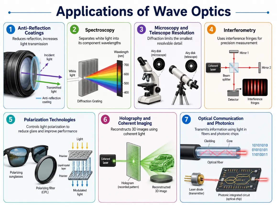
This infographic shows how wave optics supports modern technologies and scientific tools, including coatings, spectroscopy, imaging, interferometry, polarization devices, holography, and optical communication.
This infographic presents the main applications of wave optics in a clear multi-panel layout. It shows anti-reflection coatings that use thin-film interference to reduce unwanted reflection, spectroscopy using diffraction gratings to separate wavelengths, and microscopy and telescope resolution shaped by diffraction limits. It also includes interferometry for precision measurement, polarization technologies such as sunglasses and filters, holography and coherent imaging based on stable interference, and optical communication and photonics using fibres, lasers, and photonic circuits. Together, these examples show that wave optics is not only a theoretical topic but also a foundation of many modern optical systems.
Why Study Wave Optics?
It Reveals the Hidden Structure of Light
Wave optics shows that light is more than what appears to the eye. Behind brightness and colour are wavelength, phase, coherence, superposition, and polarization. Studying these ideas helps students move from surface observation to physical understanding.
It Explains Everyday Optical Effects
Soap-bubble colours, oil-film patterns, glare reduction, rainbow-like diffraction colours, and shimmering optical coatings all become more meaningful when seen through wave optics. Familiar scenes become examples of precise wave behaviour.
It Sets the Limits of Seeing
Diffraction explains why microscopes and telescopes cannot resolve unlimited detail. This is not merely a technical limitation. It is a fundamental wave limit that shapes science, astronomy, biology, engineering, and imaging technology.
It Supports Modern Optical Technology
Lasers, spectrometers, optical coatings, interferometers, holograms, displays, fibre optics, and photonic devices all depend on wave-optics principles. Students who understand these principles can better understand the design logic behind modern optical systems.
It Builds a Bridge Toward Quantum Optics
Wave optics prepares students for modern ideas about photons, probability amplitudes, quantum interference, and light-matter interaction. It is one of the most important stepping stones between classical physics and modern physics.
Common Misconceptions
Misconception 1: Wave Optics Replaces Ray Optics Completely
Wave optics does not make ray optics useless. Ray optics remains extremely helpful when wavelength effects are small compared with the scale of the system. Wave optics becomes necessary when phase, wavelength, coherence, diffraction, or polarization matters.
Misconception 2: Interference Means Waves Physically Collide
Interference does not mean waves crash like solid objects. It means their fields add according to superposition. The resulting intensity depends on whether the waves arrive in phase, out of phase, or somewhere between.
Misconception 3: Diffraction Only Happens Through Very Tiny Slits
Diffraction happens whenever waves encounter edges or openings. It is most noticeable when the aperture size is comparable to the wavelength, but it is not absent in larger openings. It may simply be too small to notice easily.
Misconception 4: Thin-Film Colours Are Just Surface Pigments
The colours in soap bubbles and oil films are mainly structural colours caused by interference. The film thickness selects which wavelengths are reinforced or weakened.
Misconception 5: Polarization Means Light Has Become More Powerful
Polarization does not mean light is stronger. It means the electric-field vibration has an organised orientation or pattern. In fact, passing light through a polarizer often reduces intensity.
Misconception 6: Coherence Is Only Important for Lasers
Lasers are important examples of coherent light, but coherence is a general wave idea. Any stable interference effect depends on some degree of coherence.
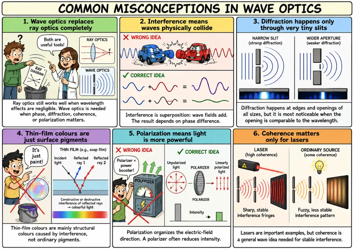
This comic corrects six common misconceptions in wave optics, showing that ray optics still matters, interference is superposition, diffraction is widespread, thin-film colours come from interference, polarization organises light, and coherence is important beyond lasers.
This educational comic presents six common misconceptions in wave optics and contrasts each with the correct physical idea. It explains that wave optics does not replace ray optics completely, but complements it when wavelength-related effects matter. It shows that interference is not a physical collision of waves, but the result of superposition and phase difference. It clarifies that diffraction occurs at edges and openings of many sizes, though it is most noticeable when dimensions are comparable to wavelength. It also explains that thin-film colours are structural colours caused by interference rather than surface pigments, that polarization organises the electric-field direction instead of making light more powerful, and that coherence is a general wave concept important for stable interference, not only for lasers. The comic helps students correct common misunderstandings while keeping the topic visually engaging.
Review Questions
Question 1
What is wave optics?
Answer: Wave optics is the study of light as a wave. It explains phenomena such as interference, diffraction, coherence, thin-film colours, diffraction gratings, and polarization.
Question 2
How does wave optics differ from geometrical optics?
Answer: Geometrical optics treats light as rays, while wave optics treats light as waves with wavelength, phase, amplitude, coherence, and polarization.
Question 3
Why is phase important in wave optics?
Answer: Phase determines how waves combine when they overlap. Waves in phase can reinforce, while waves out of phase can cancel.
Question 4
What is constructive interference?
Answer: Constructive interference occurs when waves arrive in step and reinforce each other, producing a stronger resultant intensity.
Question 5
What is destructive interference?
Answer: Destructive interference occurs when waves arrive out of step and partly or completely cancel, producing reduced intensity.
Question 6
Why does diffraction limit resolution?
Answer: Light spreads after passing through an aperture. This spreading causes point images to form finite diffraction patterns rather than perfect points, limiting how close two objects can be while still being distinguished.
Question 7
Why do thin films show colours?
Answer: Thin films reflect light from two nearby surfaces. These reflected waves interfere, reinforcing some wavelengths and weakening others.
Question 8
What is the purpose of a diffraction grating?
Answer: A diffraction grating separates light into wavelengths by using interference from many equally spaced slits or grooves.
Question 9
Why is coherence important?
Answer: Coherence allows waves to maintain stable phase relationships, which is necessary for clear and stable interference patterns.
Question 10
What does polarization reveal about light?
Answer: Polarization reveals that light is a transverse electromagnetic wave with an electric field that vibrates perpendicular to the direction of travel.
Thought-Provoking Questions
Question 1
If light usually appears smooth and continuous to our eyes, why do wave-optics experiments reveal bright and dark patterns?
Answer: Our eyes often average light over many wavelengths, directions, and phases. Wave-optics experiments are designed to separate and preserve phase relationships, making interference and diffraction patterns visible.
Question 2
Why can a tiny thickness difference in a soap bubble produce visible colour changes?
Answer: Visible wavelengths are only hundreds of nanometres long. A tiny change in film thickness can therefore change the phase relationship between reflected waves enough to reinforce or cancel different colours.
Question 3
Why is the limit of a microscope not only a matter of lens quality?
Answer: Even a perfect lens is limited by diffraction. Light from a point object spreads into a pattern rather than forming an infinitely sharp point, so close objects eventually blur together.
Question 4
Why does coherence matter so much in precision measurement?
Answer: Precision interferometry depends on stable phase relationships. If the phase relationship changes randomly, the fringe pattern becomes unstable or disappears, making accurate measurement difficult.
Question 5
How does polarization remind us that light is not just brightness?
Answer: Polarization shows that light has an electric-field direction. Two beams may have the same brightness and wavelength but different polarization states, leading to different interactions with materials and filters.
Comprehensive Numerical Problems with Solutions
Light in a vacuum travels with an operating wavelength of 600 nm. Find its frequency.
Solution:
Apply the fundamental wave equation linking speed, frequency, and wavelength:
$$c = f\lambda \Rightarrow f = \frac{c}{\lambda}$$
Convert the wavelength dimensions into uniform base meters (\(600\,\text{nm} = 600 \times 10^{-9}\,\text{m}\)):
Answer: The wave frequency is exactly 5.0 × 10¹⁴ Hz.
In a double-slit setup, light of wavelength 550 nm passes through two slits separated by 0.25 mm. If the observation screen sits 1.5 m away, calculate the net fringe spacing.
Solution:
Apply the Young’s double-slit linear fringe spacing expression:
$$\Delta y = \frac{\lambda D}{d}$$
Convert all system parameters to uniform meters layout metrics (\(\lambda = 550 \times 10^{-9}\,\text{m}\), \(D = 1.5\,\text{m}\), \(d = 0.25\,\text{mm} = 0.25 \times 10^{-3}\,\text{m}\)):
Answer: The structural grating slit spacing measures precisely 2.0 × 10⁻⁶ m.
Monochromatic light operating at wavelength 600 nm strikes a grating with slit spacing 2.0 × 10⁻⁶ m at normal incidence. Find the calculated first-order diffraction angle.
Solution:
Apply the foundational grating equation:
$$d \sin \theta = m\lambda$$
For the first-order tracking peak, set \(m = 1\), isolating the angular sine function variable:
Answer: The first-order diffraction angle resolves to approximately 17.5°.
An optical thin film matrix of refractive index 1.25 is processed as an anti-reflection quarter-wave path layer for light tracking at wavelength 500 nm. Calculate the required film thickness.
Solution:
The structural thickness parameter for an idealized quarter-wave cancellation film tracks as:
$$t = \frac{\lambda}{4n}$$
Substitute values straight into the fraction formula:
Answer: The thin-film coating thickness balances precisely at 100 nm.
A linearly polarized light beam holding an initial intensity of 80 W m−2 enters an optical analyzer oriented at an angle of 60° relative to the polarization vector field. Calculate the transmitted light intensity.
Solution:
Apply Malus’s Law expression:
$$I = I_0 \cos^2 \theta$$
Substitute the structural field values (\(I_0 = 80\,\text{W m}^{-2}\), \(\theta = 60^\circ\)):
Answer: The net transmitted light intensity measures exactly 20 W m−2.
FAQ
What is wave optics in simple terms?
Wave optics is the study of light as a wave. It explains how light overlaps, spreads, forms interference patterns, separates into wavelengths, and shows polarization.
Why is wave optics also called physical optics?
It is called physical optics because it examines the physical wave behaviour of light, including phase, wavelength, diffraction, interference, and polarization, rather than only tracing rays.
When is wave optics needed?
Wave optics is needed when the wavelength of light becomes important, such as near narrow slits, thin films, fine grooves, small apertures, coherent sources, or polarization-sensitive materials.
What is the difference between interference and diffraction?
Interference usually refers to the overlapping of waves from different paths or sources. Diffraction refers to wave spreading caused by apertures, edges, or obstacles. In many real situations, diffraction and interference work together.
Why do soap bubbles show colours?
Soap bubbles show colours because light reflected from the two surfaces of a thin film interferes. Different thicknesses reinforce or weaken different wavelengths.
Why do diffraction gratings separate colours?
Diffraction gratings have many regularly spaced slits or grooves. Waves from these repeated structures interfere constructively at angles that depend on wavelength, so different colours appear in different directions.
Why does diffraction limit image resolution?
Light from a point source spreads into a diffraction pattern rather than forming a perfect point. When two such patterns overlap too much, the two objects can no longer be clearly separated.
What is coherence?
Coherence is the stability of the phase relationship between waves. Clear interference patterns require waves with a sufficiently stable phase relationship.
Why is polarization part of wave optics?
Polarization describes the orientation of the electric field in a light wave. It is part of wave optics because it depends on the transverse electromagnetic wave nature of light.
How does wave optics connect to modern technology?
Wave optics explains light by treating it as a wave with wavelength, phase, amplitude, coherence, and polarization. It becomes essential when ray optics alone cannot explain what is observed.
The main topics in this cluster are interference, thin-film interference, diffraction and resolution, diffraction gratings, coherence and interferometry, and polarization. Each topic reveals a different way in which light’s wave nature becomes visible or useful.
Interference shows that waves can reinforce or cancel. Thin films show how tiny thickness differences become colours. Diffraction explains spreading and resolution limits. Diffraction gratings separate wavelengths. Coherence makes stable interference possible. Polarization reveals the transverse electric-field direction of light.
Wave optics is therefore both beautiful and practical. It explains colours in soap bubbles, patterns from slits, limits of microscopes, precision of interferometers, operation of polarizers, and many technologies in imaging, communication, spectroscopy, sensing, and photonics.
Reflection Question
If geometrical optics shows where light travels, and wave optics shows how light overlaps, spreads, and carries phase, what new things become visible when we stop thinking of light as only a ray?