
Fiber Optics is the study and use of thin glass or plastic fibers that guide light over distance. These fibers may look simple from the outside, but they support some of the most important technologies in modern communication, medicine, sensing, industry, and scientific research.
At the heart of fiber optics is a powerful idea from Light and Optics: light can be guided, shaped, transmitted, amplified, detected, and interpreted. In an optical fiber, light is not left to spread freely in all directions. It is confined mainly within a central core and guided along the fiber by carefully designed material boundaries.
Fiber optics connects many areas of physics. It begins with geometrical optics, where refraction and total internal reflection explain the basic guiding of light. It also connects to wave optics, because real fibers support guided modes, interference effects, dispersion, and wavelength-dependent behaviour. At a deeper level, fiber optics is part of the wider world of photonics, where light becomes a practical tool for carrying information, measuring the world, and building advanced optical systems.
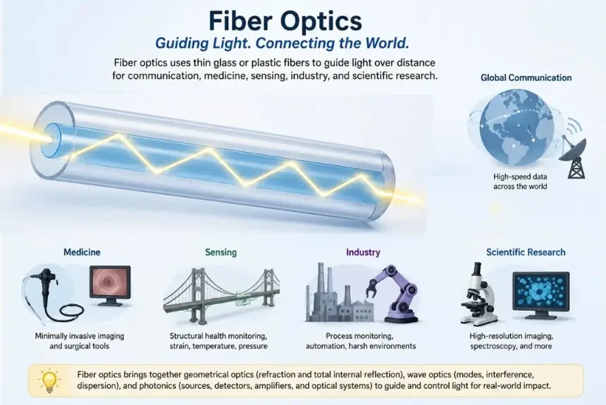
This educational infographic introduces fiber optics as the use of thin glass or plastic fibers to guide light over distance. The central diagram shows input light entering an optical fiber and being guided through the core by total internal reflection, with the core and cladding clearly indicated. Surrounding examples show how fiber optics supports global communication, minimally invasive medical imaging, structural sensing, industrial monitoring, and scientific research. The image helps students see that fiber optics is not only a cable technology, but a practical meeting point of geometrical optics, wave optics, and photonics.
What Fiber Optics REALLY Is
Fiber optics is not simply “light inside a cable”. It is a complete way of controlling light so that it can perform useful work. A fiber can carry digital information across oceans, deliver laser light into a medical instrument, detect strain in a bridge, monitor temperature along a power cable, or connect servers inside a data centre.
The key idea is that light can be treated as a signal. In communication systems, that signal may represent data. In medical systems, it may carry an image. In sensing systems, it may change in response to temperature, pressure, bending, vibration, or chemical conditions. The fiber itself may act as a pathway, a measuring device, or part of a larger optical network.
A student who studies fiber optics is therefore not only learning about a cable. They are learning how physics becomes infrastructure. The same ideas of refraction, total internal reflection, wave propagation, attenuation, dispersion, signal detection, and electromagnetic behaviour help explain the hidden light-based systems that support everyday digital life.
Learning Pathway for the Fiber Optics Cluster
This hub page introduces the main ideas of fiber optics and guides students toward the more detailed pages in the cluster. The learning sequence begins with how light is guided, then moves to how signals behave inside fibers, how communication systems use light, how loss is managed, and how fibers become sensors. Use the links below to explore the subpages:
Fiber Optics
This hub page introduces optical fibers as light-guiding structures used in communication, sensing, imaging, medicine, industry, and research.Total Internal Reflection and Optical Fibers
Learn how light remains guided inside a fiber core when it meets the core-cladding boundary under the correct conditions.Fiber Modes and Dispersion
Study how different guided modes, wavelengths, and propagation effects influence pulse spreading, bandwidth, and signal clarity.Optical Fiber Communication
Explore how transmitters, optical fibers, modulation, receivers, network components, and signal processing work together to carry information using light.Optical Amplifiers and Signal Loss
Understand attenuation, scattering, absorption, bends, connectors, splices, link budgets, optical amplifiers, amplifier noise, and signal recovery.Fiber Optic Sensors
See how optical fibers can become sensitive measuring devices for strain, temperature, vibration, pressure, chemical change, and structural monitoring.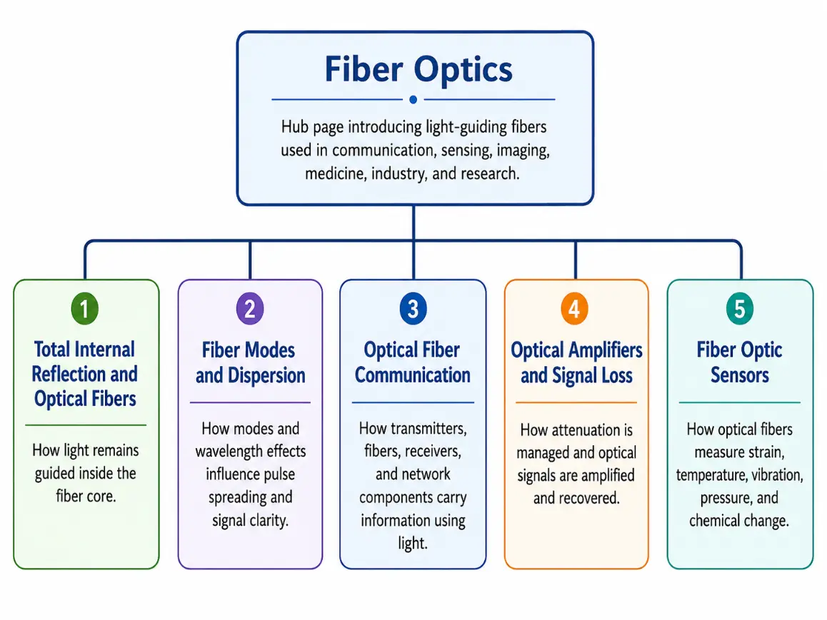
This learning pathway chart presents the structure of the Fiber Optics cluster. The Fiber Optics hub page sits at the top as the entry point for understanding light-guiding fibers used in communication, sensing, imaging, medicine, industry, and research. Below it, the five subpages form a clear learning sequence: Total Internal Reflection and Optical Fibers explains how light remains guided inside the fiber core; Fiber Modes and Dispersion examines how guided modes and wavelength effects influence pulse spreading and signal clarity; Optical Fiber Communication shows how light carries information through transmitters, fibers, receivers, and network components; Optical Amplifiers and Signal Loss explains attenuation, amplification, and signal recovery; and Fiber Optic Sensors shows how optical fibers can measure strain, temperature, vibration, pressure, and chemical change.
The Big Idea: Guiding Light Through a Fiber
An optical fiber guides light because of its layered structure. The central region, called the core, has a slightly higher refractive index than the surrounding cladding. When light travelling inside the core reaches the boundary at a suitable angle, it reflects back into the core instead of escaping into the cladding.
This repeated reflection can be described using the ray idea of total internal reflection. For many introductory purposes, this is the easiest way to visualise fiber guidance. However, a full understanding also requires the wave view, because light in a fiber forms guided modes rather than simply bouncing like a tiny ball. This is why fiber optics sits naturally between geometrical optics and wave optics. The ray picture explains the basic trapping of light, while the wave picture explains modes, dispersion, single-mode operation, polarization effects, and advanced fiber design.
Basic Structure of an Optical Fiber
A standard optical fiber has three main physical regions: the core, the cladding, and the protective coating or buffer. Each region has a different purpose.
Core: The central region where most of the guided light travels. It is usually made from high-purity glass or plastic. In long-distance communication fibers, the core must be extremely pure because even small impurities can increase signal loss.
Cladding: Surrounds the core and has a slightly lower refractive index. This refractive-index difference is essential because it allows light in the core to be guided by total internal reflection or, more accurately in wave language, by guided modes supported by the fiber structure.
Protective Coating or Buffer: The outermost layer. It does not guide the light directly. Its job is to protect the glass or plastic fiber from moisture, scratches, bending stress, crushing, and handling damage.
Core Concepts Students Should Understand
Fiber optics becomes easier when students see the subject as a set of connected ideas rather than a long list of separate terms. The most important concepts are light guidance, numerical aperture, modes, dispersion, attenuation, amplification, communication, and sensing.
Total Internal Reflection
Light can remain trapped inside the core when it travels from the higher-index core toward the lower-index cladding at a suitable angle.Critical Angle
The critical angle marks the boundary between ordinary refraction and total internal reflection for light moving from a higher-index medium to a lower-index medium.Numerical Aperture
Numerical aperture describes how much light a fiber can accept from outside. It is related to the refractive indices of the core and cladding.Modes
A mode is an allowed guided pattern of light in a fiber. Single-mode and multimode fibers behave differently because they support different numbers of guided patterns.Dispersion
Dispersion means that an optical pulse spreads out in time as it travels. This can limit data rate and transmission distance.Attenuation
Attenuation is the loss of optical power as light travels through the fiber and its components. It is usually measured in decibels per kilometre.Key Equations and What They Mean
The equations in fiber optics should not be memorised mechanically. Each equation describes one physical question: Will light be trapped? How much light can enter? How much power is lost? How fast does light travel in the fiber?
Critical Angle
For light travelling from a higher-index medium n1 to a lower-index medium n2, the critical angle is given by:
$$\sin \theta_c = \frac{n_2}{n_1}$$This equation tells us the angle at which the refracted ray would travel along the boundary. For incident angles greater than θc, total internal reflection can occur.
Numerical Aperture
For a simple step-index fiber in air, the numerical aperture is commonly written as:
$$\text{NA} = \sqrt{n_{\text{core}}^2 – n_{\text{cladding}}^2}$$A larger numerical aperture means the fiber can accept light over a wider range of input angles. However, in multimode fibers, accepting more modes may also increase modal dispersion.
Attenuation
Fiber loss over distance may be estimated using:
$$\text{Fiber loss in dB} = \alpha L$$Here, α is attenuation in dB/km and L is the fiber length in km. This equation is useful for estimating whether enough power will reach the receiver.
Speed of Light in a Fiber
The speed of light in a fiber material is approximately:
$$v = \frac{c}{n}$$Here, c is the speed of light in vacuum and n is the refractive index of the material. A higher refractive index means light travels more slowly in that medium.
Types of Optical Fibers
Single-Mode Fiber: Single-mode fiber has a very small core and supports one main guided mode. It is widely used in long-distance, high-speed communication because it greatly reduces modal dispersion and supports high bandwidth over long distances.
Multimode Fiber: Multimode fiber has a larger core and supports many guided modes. It is often used for shorter links, such as local area networks, building networks, and data centre connections, where easier light coupling and lower system cost can be important.
Glass Optical Fiber: Glass optical fiber is used in most high-performance communication systems. It offers low attenuation, good long-distance performance, and compatibility with advanced optical components.
Plastic Optical Fiber: Plastic optical fiber is usually used for shorter distances. It is easier to handle and more flexible, but it generally has higher loss than high-quality glass fiber.
Modern Applications of Fiber Optics
Fiber optics matters because it has become a hidden foundation of modern life. Many daily technologies depend on guided light travelling through fibers, even when users never see the fibers themselves.
Telecommunications and Internet Networks
Fiber optic cables carry large volumes of internet, voice, video, cloud, and data traffic across cities, countries, data centres, and submarine cable systems.Medical Imaging and Endoscopy
Fiber optics supports minimally invasive imaging, illumination, optical coherence tomography, and medical instruments that carry light into the body.Aerospace and Lightweight Systems
Fiber optic links and sensors are useful in aircraft, spacecraft, and composite structures because they are lightweight and resistant to electromagnetic interference.Industrial Automation and Monitoring
Factories, process plants, power systems, and transport networks use fiber links and sensors for reliable communication and remote monitoring in electrically noisy environments.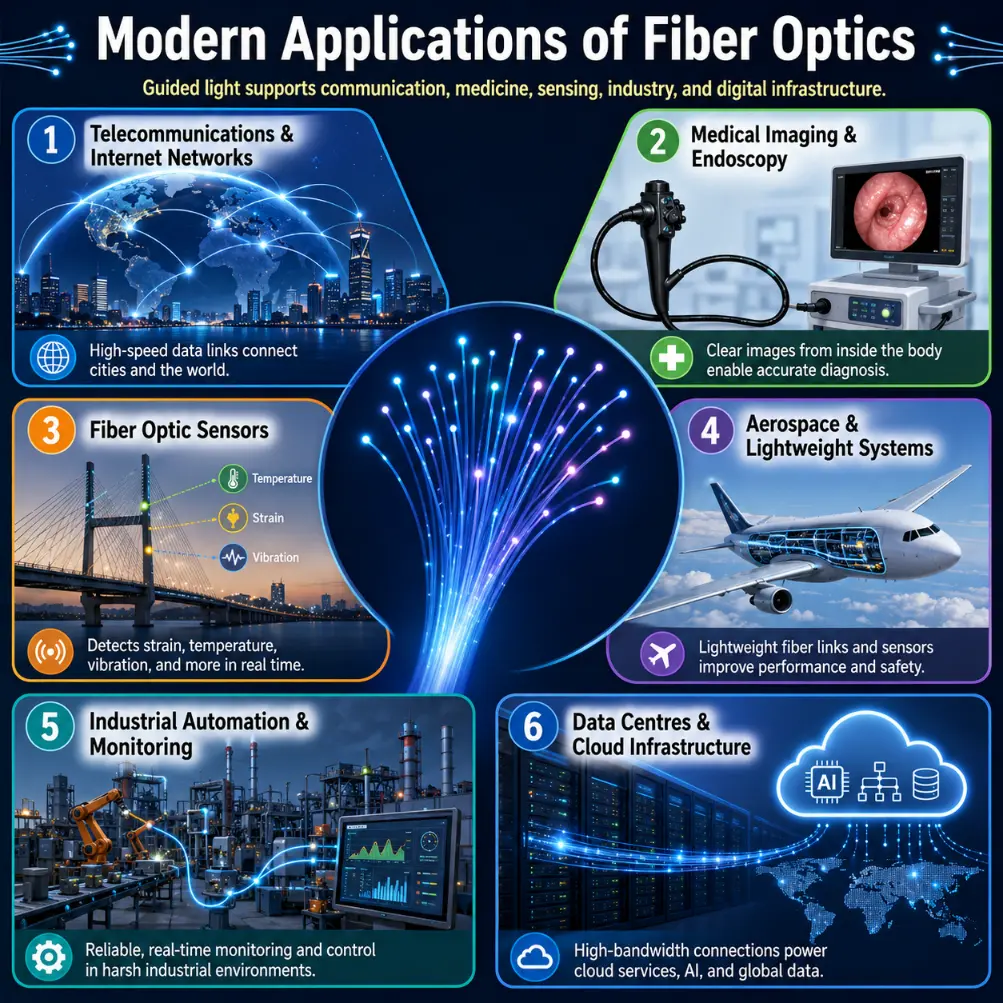
This infographic presents the modern applications of fiber optics. At the centre, a bundle of optical fibers symbolizes guided light as the foundation of the technology. Around it, six application areas are shown: telecommunications and internet networks for high-speed global data transfer; medical imaging and endoscopy for minimally invasive diagnosis and illumination; fiber optic sensors for measuring strain, temperature, vibration, and other physical changes; aerospace and lightweight systems for communication links and sensing in aircraft and spacecraft; industrial automation and monitoring for reliable operation in electrically noisy environments; and data centres and cloud infrastructure for high-speed digital services, artificial intelligence, and large-scale data transfer.
Why Fiber Optics Matters and Why to Study It
Modern society depends on fast, reliable, and high-capacity movement of information. Fiber optics provides one of the most efficient physical pathways for that movement. A single fiber can carry enormous amounts of data by using different wavelengths, advanced modulation, and sensitive receivers. Fibers are immune to electromagnetic interference, lightweight, operate over long distances, and can be used safely in high-voltage environments since they do not require electrical current at the point of measurement.
It Shows How Light Becomes Infrastructure: Fiber optics turns the abstract study of light into a real system that supports internet access, global communication, medicine, industry, and research. Students see how reflection, refraction, wave behaviour, and electromagnetic ideas become working technology.
It Builds Understanding of Communication Systems: Studying fiber optics helps students understand how information is encoded, transmitted, weakened, amplified, received, and reconstructed. This supports deeper learning in telecommunications, data networks, signal processing, and photonics.
It Connects Physics with Engineering Design: A fiber link is not designed by physics alone. Engineers must consider materials, connectors, splices, bending, attenuation, dispersion, bandwidth, receiver sensitivity, amplifiers, safety margin, and installation quality.
It Opens a Pathway to Photonics and Optical Engineering: Fiber optics introduces students to the larger field of photonics, where light is used for communication, imaging, sensing, computing, manufacturing, and scientific measurement.
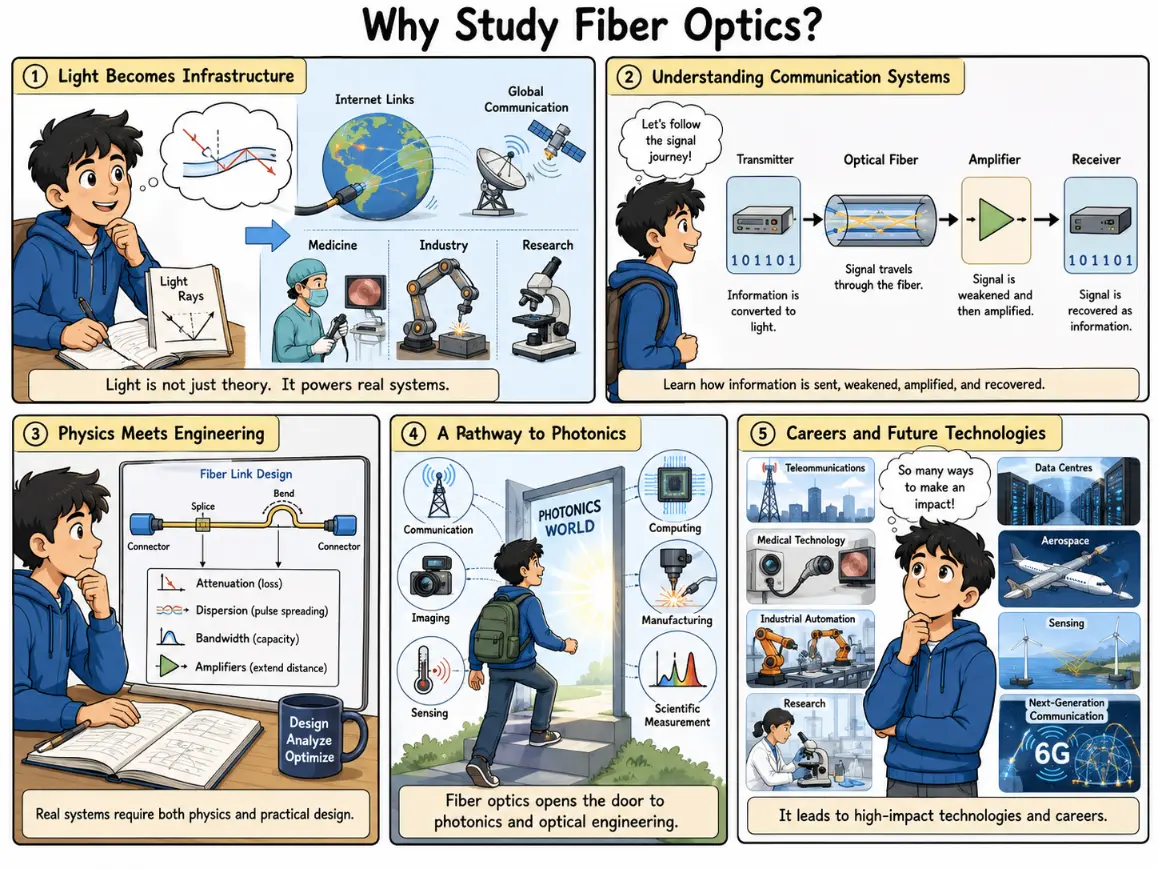
This comic-style illustration explains why studying fiber optics is valuable. It shows how abstract ideas about light, reflection, refraction, wave behaviour, and electromagnetic principles become real systems that support internet access, global communication, medicine, industry, and research. The comic also highlights how fiber optics helps students understand communication systems, including how information is encoded, transmitted, weakened, amplified, received, and reconstructed. It connects physics with engineering design by showing that real fiber links depend on materials, connectors, splices, bends, attenuation, dispersion, bandwidth, receiver sensitivity, amplifiers, safety margin, and installation quality. The illustration also presents fiber optics as a pathway into photonics and optical engineering, leading to careers in telecommunications, data centres, medical technology, aerospace, industrial automation, sensing, research, defence, and next-generation communication systems.
Common Misconceptions
The Internet Cable Limitation
Misconception: Fiber optics is only about internet telecom links. Reality: Internet links are highly visible, but fiber platforms are equally vital inside medical endoscopes, chemical biosensors, aircraft frames, and quantum encryption research labs.The Perfect Lossless Illusion
Misconception: Fiber cables exhibit completely zero signal loss over global distances. Reality: Fibers feature exceptionally low attenuation parameters, but they are not lossless. Rayleigh scattering, structural macro-bends, and connector splices continually reduce optical power levels.Interactive Quick Checks
Quick Check: Fiber Optics Hub
1. What is the main physical idea that allows light to remain guided inside a basic optical fiber?
The main idea is that light remains guided inside the higher-index core because of the refractive-index difference between the core and cladding. In the ray picture, this is explained by total internal reflection.
2. Why must the cladding have a lower refractive index than the core?
The lower-index cladding creates the essential boundary condition needed for light in the core to undergo total internal reflection. Without this index gap, light waves would pass straight out into the outer environment.
3. How is attenuation different from dispersion?
Attenuation weakens the optical signal by reducing its absolute power. Dispersion distorts the signal in time by causing pulses to spread out, which can make neighboring bits overlap.
4. Why is single-mode fiber often used for long-distance communication?
Single-mode fiber supports one main guided spatial pathway, completely removing modal dispersion. This allows data pulses to remain distinct over hundreds of kilometers.
Numerical Practice: Fiber Metrics
Numerical Problems and Solutions
Problem 1: A step-index fiber has a core refractive index of 1.48 and a cladding refractive index of 1.46. Calculate its numerical aperture (NA).
Apply the standard numerical aperture structure:
$$\text{NA} = \sqrt{n_{\text{core}}^2 – n_{\text{cladding}}^2}$$
$$\text{NA} = \sqrt{1.48^2 – 1.46^2} = \sqrt{2.1904 – 2.1316} = \sqrt{0.0588} \approx 0.24248$$Answer: The numerical aperture is approximately 0.243.
Problem 2: A long-haul transmission fiber features an attenuation constant of 0.20 dB/km. Find the total fiber power loss encountered across a length of 50 km.
Multiply the linear attenuation rate by the total link length:
$$\text{Total Loss} = \alpha \times L = 0.20\text{ dB/km} \times 50\text{ km} = 10.0\text{ dB}$$Answer: The total link fiber loss measures exactly 10 dB.
Problem 3: An optical fiber has a numerical aperture of 0.20. Estimate its maximum acceptance angle when light enters from an air interface.
The acceptance angle tracks the sine of the system’s NA inside air:
$$\theta_{\text{max}} = \sin^{-1}(\text{NA}) = \sin^{-1}(0.20) \approx 11.5369^\circ$$Answer: The maximum acceptance angle in air is approximately 11.5°.
Problem 4: Light propagates inside a silica glass core featuring a refractive index of 1.47. Estimate the velocity of light inside this medium (assume vacuum speed c = 3.00 × 10⁸ m/s).
Divide the vacuum light constant by the core medium index:
$$v = \frac{c}{n} = \frac{3.00 \times 10^8\text{ m/s}}{1.47} \approx 2.0408 \times 10^8\text{ m/s}$$Answer: The speed of light inside the fiber core is approximately 2.04 × 10⁸ m/s.
Key Terms
- Core
- The high-purity central tracking layer of an optical fiber that confines and guides passing light signals.
- Cladding
- The outer optical jacket surrounding the core that features a lower refractive index to maintain guiding boundaries.
- Numerical Aperture (NA)
- A dimensionless index value matching the maximum light cone collection capacity of a waveguide core.
- Critical Angle
- The threshold angle of incidence past which passing rays undergo total internal reflection rather than refracting outwards.
- Attenuation
- The reduction of absolute optical power density over transmission distance, measured in decibels per kilometer.
- Dispersion
- The physical phenomenon where data pulse components spread out in time along the length of a fiber path.
External References
The Fiber Optic Association — Professional landing frameworks reviewing real-world splicing, connector metrics, and active cable link diagnostics workflows.
RP Photonics Encyclopedia — High-accuracy reference definitions covering single-mode field mechanics, attenuation boundaries, and laser diode configurations.
Optica Publications — Technical databases archiving advanced research across dense wavelength multiplexing systems and integrated planar photonics grids.
International Telecommunication Union — Global compliance telecommunication standards detailing physical layer single-mode fiber core geometries.
Summary
Fiber optics is the use of guided light in thin glass or plastic fibers for communication, sensing, imaging, medicine, industry, and research. Its foundation lies in the structure of the optical fiber, especially the higher-index core, lower-index cladding, and protective outer coating. The subject begins with total internal reflection and refractive index, but it quickly expands into modes, dispersion, attenuation, numerical aperture, optical communication, optical amplification, and fiber optic sensing. This makes fiber optics a rich meeting point between physics and engineering.
Reflection Question
If a single strand of glass can carry internet traffic, medical images, industrial data, and sensing information, how should we rethink the relationship between simple physical principles and the complex systems that modern society depends on?