Prepare for University Studies & Career Advancement
Interference of Light
Interference of light is one of the clearest signs that light behaves as a wave. When two or more light waves meet, they do not simply collide like solid objects. Instead, their electric field disturbances combine. In some places, the waves reinforce each other and produce bright regions. In other places, they cancel partly or almost completely and produce dark regions. These bright and dark patterns are called interference fringes.
This page belongs to the wider study of wave optics, which functions as a structural core inside the broader field of physical science. Interference links naturally with diffraction and resolution, thin-film interference, diffraction gratings, and coherence and interferometry.
At first, interference may look mysterious because it allows light added to light to produce darkness. Yet the idea becomes simpler when we remember that light is not just “brightness moving through space.” It is an oscillating wave. What matters is not only how much light arrives, but also how the crests and troughs of the arriving waves line up.
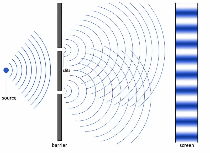
Young’s double-slit experiment shows how light waves from two narrow slits overlap to form alternating bright and dark interference fringes on a screen.
This cross-sectional diagram illustrates the basic geometry of light interference in Young’s double-slit experiment. A light source sends waves toward an opaque barrier with two narrow slits. Each slit acts as a secondary wave source, producing spreading wavefronts that overlap between the barrier and the screen. Where the waves reinforce, bright fringes appear; where they cancel, dark fringes appear. The diagram helps students connect the visible fringe pattern with the wave nature of light.
The Evolutionary Path: History, System Barriers, and Foundry Paradigms
The progression of interference mechanics from an experimental demonstration into a foundational engineering standard revolutionized wave modulation and thin-film system processing.
The Historical Journey
The formal proof of light interference began in 1801 when Thomas Young split a single light wavefront using two parallel slits, directly challenging classical particle models. This wave logic advanced in 1818 when Augustin-Jean Fresnel introduced a comprehensive mathematical framework that detailed how overlapping wave components combine based on their relative phases. By the late nineteenth century, the creation of highly precise mirror-splitting configurations by Albert Michelson allowed researchers to split a single light channel into two perpendicular paths, using micro-scale fringe shifts to verify material properties. The field gained immense stability in the 1960s with the invention of the laser, providing semiconductor and optoelectronic foundries with long, predictable light channels required for deep micromanufacturing.
Contemporary Technical Hurdles
The principal limitation in modern multi-layer coating facilities is preventing **spatial phase decoherence caused by surface layer variations**. When engineering advanced thin-film filters, light reflecting from the top boundary must interfere perfectly with light returning from the lower substrate layer. If the manufactured coating thickness varies by even a fraction of a nanometer across the surface, the relative optical paths tilt out of alignment. This minor structural error introduces chaotic phase variations that degrade the target cancellation zones, transforming sharp color filters into broad, leaky transmission channels.
Future Paradigms: Wavefront Engineering and Metamaterial Modulation
Modern micro-optics foundries bypass these classical overlay errors by integrating specialized sub-wavelength spatial modulators and automated phase-locking loops:
Digital Phase-Locking Spatial Modulators: To achieve absolute control over overlapping wavefront segments, engineering labs deploy high-speed liquid-crystal-on-silicon (LCOS) display matrices. These dynamic surfaces shift individual pixel phase properties in real-time, correcting structural path errors automatically to sustain uniform interference fields across complex uneven targets.
Resonant Metamaterial Phase Synthesizers: Next-generation optical filters deploy arrays of engineered silicon nano-posts that manipulate light properties directly at the boundary layer. By introducing customized phase tracking maps across a single flat plane, these micro-structures eliminate the need for multi-layer chemical coatings entirely, rendering precise reflection fields through a single lithography track.
Learning Pathway: Where Interference Fits in Wave Optics
Interference is often the first deep doorway into wave optics because it shows that light carries phase information. Once students understand how overlapping waves produce patterns, many later topics in optics become easier to follow.
Explains how light waves can have a preferred direction of vibration, leading to effects used in glare reduction, polarized lenses, LCD screens, stress analysis, and optical filtering.
Shows how many closely spaced openings or lines use interference to separate light into spectra and measure wavelength with high precision.
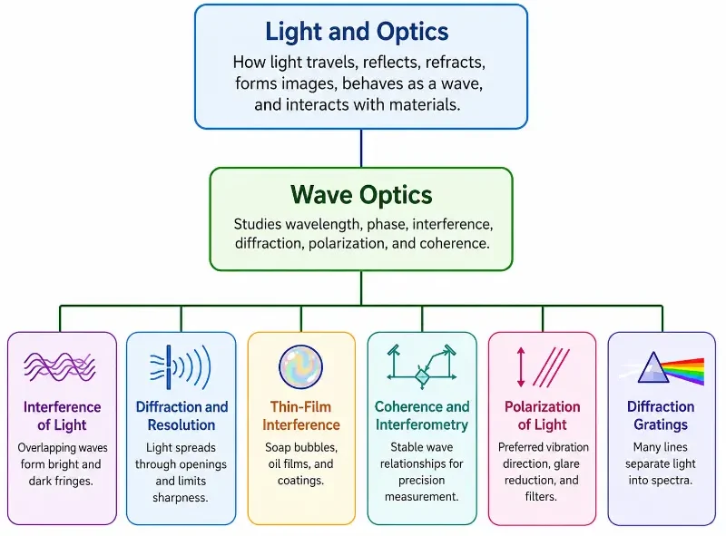
This 1-1-6 learning pathway shows how Wave Optics sits within Light and Optics and branches into six connected subtopics.
This hierarchical chart presents the structure of the Wave Optics cluster. Light and Optics forms the parent topic, Wave Optics acts as the central subtopic, and six linked pages extend from it: Interference of Light, Diffraction and Resolution, Thin-Film Interference, Coherence and Interferometry, Polarization of Light, and Diffraction Gratings. The diagram helps students see that interference is part of a wider family of wave-based optical ideas involving wavelength, phase, diffraction, polarization, coherence, and spectral separation.
What Interference of Light REALLY Means
Interference of light means that the wave disturbances from two or more light sources combine at each point in space. The final brightness at that point depends on whether the arriving waves are in step, out of step, or somewhere in between.
A bright fringe forms when the waves arrive mainly in phase. This means the crest of one wave arrives with the crest of another wave, and the trough of one wave arrives with the trough of another. Their effects reinforce. The resulting amplitude is larger, so the intensity is greater.
A dark fringe forms when the waves arrive mainly out of phase. This means the crest of one wave arrives with the trough of another. Their effects oppose each other. If the waves have equal amplitude and are exactly opposite in phase, the cancellation can be almost complete.
This is the quiet surprise of interference: adding two light waves does not always produce brighter light. The result depends on phase. In wave optics, brightness is not decided by quantity alone. It is decided by relationship.
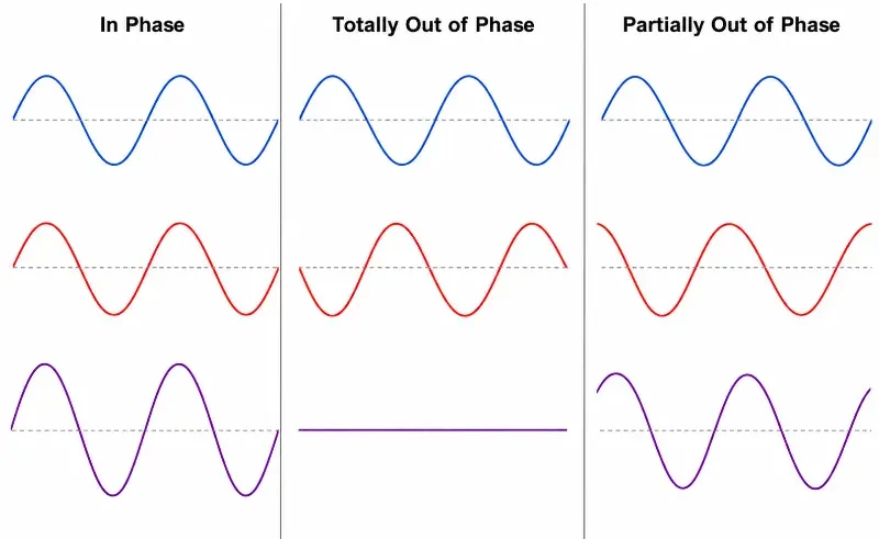
This three-panel diagram shows how the phase relationship between two waves affects the resulting wave: reinforcement occurs when the waves are in phase, cancellation occurs when they are totally out of phase, and partial reinforcement and cancellation occur when they are only partly out of phase.
This diagram shows how two light waves combine when they meet. When the waves rise and fall together, their effects reinforce and a larger wave is formed. When one wave rises while the other falls by the same amount, they cancel and the result becomes zero. When the waves are only partly out of step, the final wave is neither fully strengthened nor fully cancelled. This helps explain why light interference can produce bright regions, dark regions, and intermediate patterns.
Superposition: The Basic Rule Behind Interference
The principle of superposition says that when two or more waves meet at a point, the resulting displacement is the algebraic sum of the individual displacements. For light, the wave quantity being combined is the electric field disturbance.
Although light waves are electromagnetic waves, the basic idea can be understood using water waves or waves on a rope. If two upward pulses meet, they produce a larger upward pulse. If an upward pulse meets an equal downward pulse, they cancel temporarily. After crossing, the waves continue moving. The waves do not permanently destroy each other; they simply combine while they overlap.
For light, the same principle explains bright and dark interference fringes. Where the electric fields reinforce, the light intensity increases. Where the electric fields cancel, the intensity decreases.
Quick Check: Superposition and Interference
Question 1: Two identical waves meet at a point. At that instant, both waves have positive displacement. What happens to the resulting displacement?
The resulting displacement becomes larger because the two positive displacements add together. This is constructive superposition.
Question 2: One wave has displacement \(+A\) and another wave has displacement \(-A\) at the same point. What is the resulting displacement?
The resulting displacement is zero because \(+A + (-A) = 0\). The two waves cancel at that point.
Question 3: If two waves overlap and produce a larger wave, have the original waves been permanently changed?
No. The waves simply combine while they overlap. After passing through each other, they continue travelling. Superposition does not mean the waves permanently merge into one wave.
Question 4: In light interference, what wave quantity is being added together?
For light, the electric field disturbances are being added. Where the electric fields reinforce, the light intensity increases. Where they cancel, the light intensity decreases.
Question 5: Why can light plus light sometimes produce darkness?
Light plus light can produce darkness when the two light waves arrive out of phase. At that point, the electric field from one wave cancels the electric field from the other, producing destructive interference.
Constructive Interference
Constructive interference occurs when two light waves arrive in phase or nearly in phase. Their electric field amplitudes add together, producing a larger resultant amplitude and therefore a brighter region.
For two coherent waves, constructive interference occurs when the path difference is a whole number of wavelengths:
$$\Delta L = m \lambda$$
where \(\Delta L\) is the path difference, \(\lambda\) is the wavelength of light, and m = 0, 1, 2, 3, … is the order of the bright fringe.
Destructive Interference
Destructive interference occurs when two light waves arrive half a cycle out of phase. A crest from one wave meets a trough from the other, so the waves cancel partly or fully.
For two coherent waves, destructive interference occurs when the path difference is an odd number of half-wavelengths:
$$\Delta L = \left(m + \frac{1}{2}\right)\lambda$$
where m = 0, 1, 2, 3, … gives the order of the dark fringe.
Phase Difference and Path Difference
Two ideas control most interference problems: phase difference and path difference. They describe the same relationship from two slightly different viewpoints.
Phase Difference
Phase difference tells us how far one wave is ahead of or behind another in its cycle. One full cycle corresponds to \(2\pi\) radians or 360°. A phase difference of 0, \(2\pi\), \(4\pi\), and so on means the waves are in phase. A phase difference of \(\pi\), \(3\pi\), \(5\pi\), and so on means the waves are out of phase.
In simple terms, phase difference tells us whether the arriving waves “keep time” with each other. Waves that keep the same timing can produce stable interference patterns. Waves whose phase relationship changes randomly will not produce a clear, steady pattern.
Path Difference
Path difference is the difference between the distances travelled by two waves before reaching the same point. If one wave travels slightly farther than the other, it may arrive with a different phase.
The relationship between phase difference φ and path difference \(\Delta L\) is:
$$\phi = \frac{2\pi \Delta L}{\lambda}$$
This equation says that a path difference of one wavelength produces a phase difference of \(2\pi\), which brings the waves back into phase. A path difference of half a wavelength produces a phase difference of \(\pi\), which makes the waves opposite in phase.
Why Coherent Sources Are Needed
A stable interference pattern requires coherent sources. Two sources are coherent when they maintain a constant phase relationship. They do not need to be in phase at every moment, but their phase difference must remain stable over time.
Ordinary lamps do not usually produce clear interference patterns by simply placing two bulbs side by side. Their atoms emit light independently and randomly, so the phase relationship changes too quickly. The bright and dark fringes shift so rapidly that the eye sees only an average brightness.
Young’s double-slit experiment solves this problem by using one light source and splitting the same wavefront into two parts. The two slits behave like two related sources because the light passing through them comes from the same original wave. This allows a steady interference pattern to form.
This idea later becomes important in coherence and interferometry, where stable phase relationships are used to measure extremely small distances and changes.
Young’s Double-Slit Experiment
Young’s double-slit experiment is one of the most important experiments in the history of optics. It shows that light can produce an interference pattern, which strongly supports the wave model of light.
In the experiment, light passes through two narrow slits separated by a small distance. Each slit acts like a source of light waves. The waves spread out from the slits and overlap on a screen. Because the waves travel different distances to different points on the screen, they arrive with different phase relationships.
At some points, the path difference is a whole number of wavelengths. The waves arrive in phase and produce bright fringes. At other points, the path difference is an odd number of half-wavelengths. The waves arrive out of phase and produce dark fringes.
Central Bright Fringe
The central bright fringe forms directly opposite the midpoint between the two slits. At this point, the distances from the two slits to the screen are equal. The path difference is zero, so the waves arrive in phase.
For the central bright fringe:
$$\Delta L = 0$$
This corresponds to the order m = 0. The central fringe is often the brightest and most symmetrical part of the interference pattern.
Bright Fringes
Bright fringes appear where the path difference is:
$$\Delta L = m\lambda$$
For small angles in a double-slit arrangement, the position of the m-th bright fringe on the screen can be approximated by:
$$y_m = \frac{m\lambda D}{d}$$
where ym is the distance of the bright fringe from the central maximum, D is the distance from the slits to the screen, and d is the separation between the two slits.
Dark Fringes
Dark fringes appear where the path difference is:
$$\Delta L = \left(m + \frac{1}{2}\right)\lambda$$
For small angles, the position of the m-th dark fringe can be approximated by:
The first dark fringe on either side of the central maximum corresponds to m = 0.
Fringe Spacing in a Double-Slit Pattern
One of the most useful results from Young’s double-slit experiment is the formula for fringe spacing. The distance between neighbouring bright fringes, or neighbouring dark fringes, is:
$$\Delta y = \frac{\lambda D}{d}$$
This formula shows how the pattern changes when the wavelength, screen distance, or slit separation changes.
A larger wavelength λ produces wider fringe spacing.
A larger screen distance D produces wider fringe spacing.
A larger slit separation d produces narrower fringe spacing.
This is a powerful equation because it allows the wavelength of light to be measured from a visible pattern on a screen. A very small wavelength can be inferred from a much larger measurable fringe spacing.
Key Terms
Approximate position of bright fringes on the screen
$$y_m \approx \frac{m\lambda D}{d}$$ This gives the approximate distance of the \(m\)-th bright fringe from the central bright fringe when the angle is small.
Bright-fringe angle
$$d \sin \theta = m\lambda$$ This gives the angular direction of the \(m\)-th bright fringe.
Constructive interference
$$\Delta L = m\lambda$$ Bright fringes occur when the path difference is a whole number of wavelengths.
Destructive interference
$$\Delta L = \left(m + \frac{1}{2}\right)\lambda$$ Dark fringes occur when the path difference is an odd number of half-wavelengths.
Fringe spacing on the screen
$$\Delta y \approx \frac{\lambda D}{d}$$ This is the distance between neighbouring bright fringes, or neighbouring dark fringes, on the screen. It is not the same as the path difference \(\Delta L\).
Path difference at an angle
$$\Delta L = d \sin \theta$$ This is the difference between the two path lengths from the slits to a point observed at angle θ.
Phase difference from path difference
$$\phi = \frac{2\pi \Delta L}{\lambda}$$ A path difference can be converted into a phase difference.
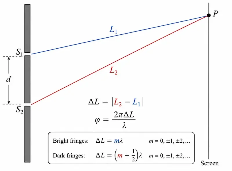
This diagram shows how two light paths from a double-slit arrangement reach the same point on the screen with a path difference ΔL, which determines the phase difference and whether bright or dark interference occurs.
This illustration shows how interference in a double-slit experiment can be understood through path difference and phase difference. Light travels from the two slits, S₁ and S₂, to the same point P on the screen along two different paths, labelled L₁ and L₂. The path difference is the difference between these two distances, written as ΔL = |L₂ − L₁|. This path difference produces a phase difference between the two waves, given by φ = 2πΔL/λ. When the path difference is a whole number of wavelengths, the waves reinforce and a bright fringe is formed. When the path difference is an odd number of half-wavelengths, the waves cancel and a dark fringe is formed.
Fringe Positions When the Angle Is Not Very Small
The familiar double-slit formula \(\Delta y \approx \frac{\lambda D}{d}\) is useful when the interference angles are small. It treats the fringes on the screen as almost equally spaced. However, this is an approximation. When the angle becomes larger, the bright fringes on a flat screen become slightly farther apart as we move away from the central bright fringe.
For bright fringes, the exact angular condition is:
$$d \sin \theta_m = m\lambda$$
where d is the slit separation, θm is the angle of the \(m\)-th bright fringe, m is the fringe order, and λ is the wavelength of light.
If the screen is flat and placed a distance D from the slits, the position of the \(m\)-th bright fringe is:
$$y_m = D \tan \theta_m$$
Since \(\sin \theta_m = \frac{m\lambda}{d}\), the exact screen position may be written as:
$$y_m = D \tan \left[\sin^{-1}\left(\frac{m\lambda}{d}\right)\right]$$
This equation shows why the spacing is not exactly constant. The angle does not translate linearly into screen position when the fringe is far from the centre. The farther the fringe is from the central maximum, the more the flat-screen geometry stretches the pattern.
Exact Spacing Between Neighbouring Bright Fringes
The spacing between the \(m\)-th and \((m+1)\)-th bright fringes on the screen is:
$$s_m = y_{m+1} – y_m$$
where:
$$y_m = D \tan \left[\sin^{-1}\left(\frac{m\lambda}{d}\right)\right]$$
Unlike the small-angle result, this exact spacing sm changes with m. Near the centre it is almost constant, but farther from the centre it gradually increases.
Physical Meaning of Bright and Dark Fringes
A bright fringe does not mean that light has gathered there like dust piling up on a surface. It means that the electromagnetic fields from the two paths reinforce at that location. The energy flow associated with the wave is stronger there.
A dark fringe does not mean that light has disappeared into nothing. It means that, at that point, the fields from the two paths cancel or nearly cancel. The energy that might have appeared there is redistributed into the bright regions. Interference rearranges intensity; it does not violate energy conservation.
This is why interference is such a deep idea. It shows that nature does not always distribute light smoothly. When waves keep a stable relationship, they can create structure: bright, dark, bright, dark, like a hidden order made visible.
Quick Check: Bright and Dark Fringes
Question 1: Does a bright fringe mean that light has physically piled up at that point like dust on a surface?
No. A bright fringe means that the electric fields from the two light paths reinforce at that point. The wave effect is stronger there, so the light intensity is higher.
Question 2: What is happening to the electromagnetic fields at a bright fringe?
The electromagnetic fields arrive mainly in phase. Their electric field disturbances add together, so the resulting wave has greater amplitude and the intensity becomes larger.
Question 3: Does a dark fringe mean that light energy has disappeared?
No. A dark fringe means that the fields cancel or nearly cancel at that point. The energy is not destroyed; the interference pattern redistributes intensity into the brighter regions.
Question 4: Why can one part of the screen be bright while a nearby part is dark?
The path difference from the two slits changes from point to point on the screen. At some positions, the waves arrive in phase and reinforce. At nearby positions, they arrive out of phase and cancel.
Question 5: What does an interference pattern reveal about light?
It reveals that light behaves as a wave with phase. The bright and dark pattern appears because the waves keep a stable relationship as they overlap.
Question 6: Why is interference described as rearranging intensity rather than creating or destroying light?
Interference changes where the intensity appears on the screen. Some regions become brighter and others darker, but the overall energy is redistributed rather than lost.
Real-World Applications of Light Interference
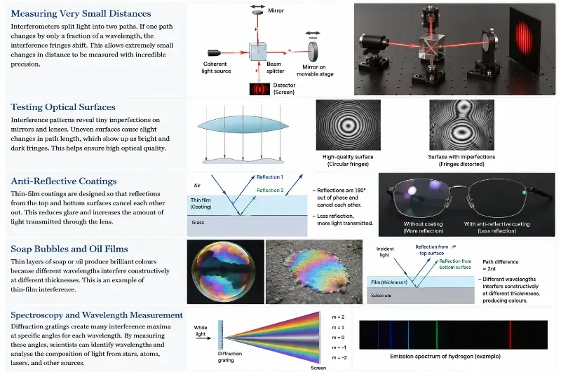
Interference is not only a laboratory effect. It appears in optical instruments, measurement systems, coatings, scientific imaging, and modern technology. Many applications depend on the fact that very small changes in path length can produce noticeable changes in brightness.
Measuring Very Small Distances
Interferometers use interference patterns to measure extremely small changes in distance. If one light path changes by a fraction of a wavelength, the interference pattern shifts. This makes interferometry useful in precision engineering, surface testing, gravitational-wave detection, and optical metrology.
Testing Optical Surfaces
High-quality mirrors and lenses must have very smooth surfaces. Interference patterns can reveal tiny imperfections because uneven surfaces change the path length of reflected light. A surface error too small to see directly can become visible through a fringe pattern.
Anti-Reflective Coatings
Some lens coatings are designed so that reflected waves cancel each other. This reduces unwanted glare and allows more light to pass through the lens. The same principle is used in camera lenses, spectacles, microscope optics, and solar cells.
Soap Bubbles and Oil Films
The colours seen in soap bubbles and oil films come from interference between light reflected from the top and bottom surfaces of a thin layer. Different wavelengths interfere constructively at different thicknesses, producing shifting colours. This connects interference of light with thin-film interference.
Spectroscopy and Wavelength Measurement
Interference ideas also support devices that separate and measure light by wavelength. In diffraction gratings, many closely spaced lines produce sharp interference maxima that help scientists identify wavelengths and analyse light from atoms, stars, lasers, and materials.
Light interference appears in many practical technologies, from precision measurement and optical testing to anti-reflective coatings, soap-bubble colours, oil-film patterns, and spectroscopy.
This infographic shows how light interference moves from theory into real-world applications. Interferometers use shifting fringe patterns to measure very small changes in distance. Optical surface testing uses interference patterns to reveal tiny imperfections in lenses and mirrors. Anti-reflective coatings reduce glare by making reflected waves cancel each other. Soap bubbles and oil films display changing colours because different wavelengths interfere at different film thicknesses. Diffraction gratings use interference to separate light into spectra, helping scientists measure wavelengths and identify the composition of light sources.
Interference, Diffraction, and the Wave Nature of Light
Interference and diffraction are closely related. Interference usually refers to the combination of waves from two or more distinct paths or sources. Diffraction refers to the spreading of waves when they pass through openings or around obstacles. In many real optical systems, both effects occur together.
For example, each slit in Young’s double-slit experiment does not simply send a narrow ray forward. The light diffracts through each slit, spreads out, and then overlaps with light from the other slit. The final pattern on the screen is therefore a combination of diffraction from each slit and interference between the two slits.
This connection prepares students for the next topic, diffraction and resolution, where the spreading of light places a real physical limit on how sharply objects can be seen.
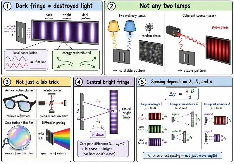
Common Misconceptions About Interference of Light
Misconception 1: Dark Fringes Mean Light Has Been Destroyed
Dark fringes are not places where energy has vanished. They are places where the electric fields from two waves cancel locally. The energy is redistributed into the bright fringes. The total energy is still conserved.
Misconception 2: Any Two Light Sources Can Produce Clear Interference
Two ordinary lamps usually do not produce a stable interference pattern because their phase relationship changes randomly. Clear interference requires coherence, which means the waves must maintain a stable phase relationship.
Misconception 3: Interference Is Only a Special Laboratory Trick
Interference appears in many practical systems, including anti-reflective coatings, precision measurement, optical testing, spectroscopy, and thin-film colours. It is one of the working principles behind many modern optical technologies.
Misconception 4: The Central Bright Fringe Is Bright Because It Is Closer
The central bright fringe is bright mainly because the path difference from the two slits is zero, so the waves arrive in phase. Its brightness is not simply due to distance. It is due to phase agreement.
Misconception 5: Fringe Spacing Depends Only on Wavelength
Wavelength is important, but fringe spacing also depends on the distance to the screen and the separation between the slits. The formula \(\Delta y = \frac{\lambda D}{d}\) shows all three factors clearly.
This comic-style visual guide helps students correct common misunderstandings about light interference, including why dark fringes do not mean destroyed light and why stable fringes require coherent waves.
This visual guide explains five common misconceptions about interference of light in a visual and student-friendly way. It shows that dark fringes are caused by local cancellation, not by the destruction of light. It also explains why ordinary lamps do not usually produce stable interference patterns, why interference is used in real technologies, why the central bright fringe forms because of zero path difference, and why fringe spacing depends on wavelength, screen distance, and slit separation.
Study Tips for Interference Problems
Start by identifying whether the question is asking about bright fringes, dark fringes, or fringe spacing.
Convert all measurements into SI units before substituting into equations.
Use \(\Delta L = m\lambda\) for bright fringes and \(\Delta L = \left(m + \frac{1}{2}\right)\lambda\) for dark fringes.
Remember that the central bright fringe corresponds to m = 0.
For double-slit fringe spacing, use \(\Delta y = \frac{\lambda D}{d}\).
Check whether the answer becomes wider or narrower in a physically sensible way.
Review Questions
Question 1: What is interference of light?
Answer: Interference of light is the combination of two or more light waves, producing regions of increased intensity and reduced intensity depending on their phase relationship.
Question 2: What condition produces constructive interference?
Answer: Constructive interference occurs when waves arrive in phase, usually when the path difference is \(m\lambda\).
Question 3: What condition produces destructive interference?
Answer: Destructive interference occurs when waves arrive out of phase, usually when the path difference is \(\left(m + \frac{1}{2}\right)\lambda\).
Question 4: Why are coherent sources needed for a stable interference pattern?
Answer: Coherent sources maintain a constant phase relationship, allowing the bright and dark fringes to remain stable over time.
Question 5: Why does Young’s double-slit experiment support the wave model of light?
Answer: It produces an interference pattern of bright and dark fringes, which is naturally explained by the superposition of waves.
Question 6: What happens to fringe spacing if the wavelength of light increases?
Answer: The fringe spacing increases because \(\Delta y = \frac{\lambda D}{d}\).
Question 7: What happens to fringe spacing if the slit separation increases?
Answer: The fringe spacing decreases because slit separation d is in the denominator of the fringe spacing formula.
Question 8: Why does a dark fringe not mean that energy has been destroyed?
Answer: The waves cancel locally at the dark fringe, but the energy is redistributed to other regions, especially the bright fringes.
Comprehensive Numerical Problems with Solutions
In a double-slit experiment, light of wavelength 500 nm passes through slits separated by 0.20 mm. If the screen is positioned 1.0 m away, find the baseline fringe spacing.
Solution:
Apply the small-angle fringe spacing formula:
$$\Delta y = \frac{\lambda D}{d}$$
Convert the initial system dimensions to standard meters (\(\lambda = 500 \times 10^{-9}\ \text{m}\), \(D = 1.0\ \text{m}\), \(d = 0.20 \times 10^{-3}\ \text{m}\)):
Answer: The linear fringe spacing on the tracking screen is exactly 2.50 mm.
A double-slit testing track records a regular fringe spacing of 2.0 mm. If the slit separation measures 0.40 mm and the observation distance tracks at 1.6 m, resolve the operating light wavelength.
Solution:
Isolate the wavelength tracking variable from the fringe expression:
$$\lambda = \frac{\Delta y d}{D}$$
Convert dimensions to standard SI coordinates (\(\Delta y = 2.0 \times 10^{-3}\ \text{m}\), \(d = 0.40 \times 10^{-3}\ \text{m}\), \(D = 1.6\ \text{m}\)):
Answer: The monochromatic light source wavelength measures exactly 500 nm.
In a double-slit testing array, the slit interval is 0.50 mm, the active wavelength is 650 nm, and the screen sits 2.0 m away. Compute the geometric distance of the third bright fringe relative to the central maximum.
Solution:
Apply the bright fringe position equation:
$$y_m = \frac{m\lambda D}{d}$$
For the third order bright fringe tracking zone, substitute \(m = 3\) using standard base meters (\(\lambda = 650 \times 10^{-9}\ \text{m}\), \(D = 2.0\ \text{m}\), \(d = 0.50 \times 10^{-3}\ \text{m}\)):
Answer: The third bright maximum forms precisely 7.80 mm from the central baseline.
Two coherent rays intersect at a specific coordinate tracking a net path difference parameter of 1.5λ. Determine whether this local overlay behaves constructively or destructively.
Solution:
Express the fractional path value as a mixed coefficient array:
$$\Delta L = 1.5\lambda = \left(1 + \frac{1}{2}\right)\lambda$$
This tracks identically with the generalized half-wavelength cancellation expression:
$$\Delta L = \left(m + \frac{1}{2}\right)\lambda$$
Setting \(m = 1\) confirms an out-of-phase condition where crest waves match trough steps perfectly.
Answer: The localized wave overlap behaves destructively, creating a dark fringe band.
Two light waves running at a wavelength of 600 nm meet at a point with an absolute structural path difference of 300 nm. Calculate the resulting phase difference in radians.
Solution:
Apply the wave path-to-phase conversion equation:
$$\phi = \frac{2\pi \Delta L}{\lambda}$$
Substitute the coordinate values directly (\(\Delta L = 300\ \text{nm}\), \(\lambda = 600\ \text{nm}\)):
Answer: The two converging light pathways carry a phase difference of exactly \(\pi\) radians.
Using the exact geometric trigonometric relations, calculate the absolute linear spacing separating the 20th and 21st bright fringes for a setup where λ = 600 nm, d = 0.30 mm, and D = 2.0 m.
Solution:
The exact coordinate location of a bright fringe on a flat screen maps as:
$$y_m = D \tan \left[\sin^{-1}\left(\frac{m\lambda}{d}\right)\right]$$
Answer: The exact distance separating the two outer bright fringes measures precisely 4.010 mm.
Frequently Asked Questions
Question 1: What is interference of light?
Answer: Interference of light occurs when two or more light waves overlap and combine. At some points, the waves reinforce and produce bright fringes. At other points, they cancel partly or almost completely and produce dark fringes.
Question 2: Why can light added to light produce darkness?
Answer: Light can produce darkness when two waves arrive out of phase. At that point, the electric field from one wave is opposite to the electric field from the other wave, so the two effects cancel locally.
Question 3: What is the difference between path difference and fringe spacing?
Answer: Path difference, \(\Delta L\), is the difference between the two distances travelled by light from the two slits to a point on the screen. Fringe spacing, \(\Delta y\), is the distance between neighbouring bright fringes or neighbouring dark fringes on the screen. They are related, but they are not the same physical quantity.
Question 4: Why is the central bright fringe bright?
Answer: The central bright fringe is bright because the two paths from the slits to the central point on the screen are equal. The path difference is zero, so the waves arrive in phase and reinforce each other.
Question 5: Do dark fringes mean that light energy has been destroyed?
Answer: No. A dark fringe means that the fields cancel locally at that position. The energy is redistributed into other parts of the pattern, especially the bright fringes. Interference rearranges intensity; it does not destroy energy.
Question 6: Why are coherent sources needed for clear interference fringes?
Answer: Clear fringes require a stable phase relationship between the waves. Coherent sources maintain this relationship long enough for a steady pattern to appear. Ordinary lamps usually do not produce clear double-slit fringes because their phase relationships change randomly and rapidly.
Question 7: Is Young’s double-slit experiment only important historically?
Answer: No. Young’s double-slit experiment is historically important, but the idea behind it remains central to modern optics. Interference is used in precision measurement, optical testing, anti-reflective coatings, spectroscopy, and advanced scientific instruments.
Question 8: Why are double-slit fringes often treated as equally spaced?
Answer: Near the central fringe, the angles are usually small, so the fringe positions are well approximated by \(y_m \approx \frac{m\lambda D}{d}\). Farther from the centre, the exact relation \(y_m = D \tan \left[\sin^{-1}\left(\frac{m\lambda}{d}\right)\right]\) shows that the spacing gradually increases on a flat screen.
External References
The following external references provide additional background from established scientific, institutional, or reference sources. They are included for wider reading and do not replace the explanations on this page.
Interference of light occurs when two or more light waves overlap and combine. If the waves arrive in phase, they reinforce and produce bright fringes. If they arrive out of phase, they cancel partly or fully and produce dark fringes.
The key idea is that light has phase. A path difference can create a phase difference, and this phase difference determines whether the resulting intensity becomes greater or smaller. Young’s double-slit experiment makes this wave behaviour visible through a regular pattern of bright and dark fringes.
The central equations \(\Delta L = m\lambda\), \(\Delta L = \left(m + \frac{1}{2}\right)\lambda\), and \(\Delta y = \frac{\lambda D}{d}\) allow students to connect the pattern on a screen with the wavelength of light and the geometry of the experiment.
Interference is not merely a classroom demonstration. It supports precision measurement, optical coatings, surface testing, spectroscopy, and many advanced optical technologies. It reveals a subtle truth: light is not only something that shines. It is something that keeps rhythm, carries phase, and forms patterns when its waves meet.
Reflection Question
If two beams of light can combine to produce darkness at some points, what does that tell us about the difference between thinking of light as “brightness” and thinking of light as a wave?