
Geometrical optics is the study of light using rays. Instead of beginning with the full wave nature of light, it follows the path of light as straight lines that reflect, refract, spread, converge, and form images. This simple ray model is not the whole story of light, but it is one of the most useful starting points for understanding how many everyday optical effects and instruments work.
When light strikes a mirror, passes through glass, enters water, travels through a lens, or forms an image in the eye, its path can often be understood by drawing a few carefully chosen rays. These ray diagrams help students see why a plane mirror forms an image behind the mirror, why a straw appears bent in water, why a magnifying glass enlarges nearby objects, why a concave mirror can focus light, and why a camera or microscope must place lenses and image planes in precise positions.
This page introduces geometrical optics as a bridge between simple observations and practical optical design. It brings together reflection and plane mirrors, refraction and Snell’s Law, lenses and image formation, mirrors and image formation, optical instruments, and aberrations and optical design. Together, these topics show how the direction of light can be controlled to see, record, project, magnify, correct, and measure the world more clearly.
The aim is not merely to memorise rules such as “angle of incidence equals angle of reflection” or formulas such as Snell’s Law. The deeper aim is to understand how light behaves at surfaces and boundaries, and how that behaviour leads to real images, virtual images, magnification, field of view, focusing, distortion, and optical correction. Once these ideas are clear, optical devices become less mysterious: they are carefully arranged systems that guide light along useful paths.
A visually detailed representation of geometrical optics, illustrating light rays undergoing reflection, refraction, and dispersion through mirrors, lenses, and prisms.
What Geometrical Optics Really Is
Geometrical optics is a way of studying light by following its path. Instead of describing light first as a wave or as photons, we begin with a simpler model: light travels along rays. A ray is not a physical thread of light, but a useful line that shows the direction in which light energy travels.
This ray model works especially well when the objects, mirrors, lenses, openings, and instruments involved are much larger than the wavelength of light. In such situations, we can often understand what happens by drawing straight lines, applying reflection and refraction rules, and locating where rays meet or appear to meet.
The strength of geometrical optics is that it turns light behaviour into geometry. A mirror image can be understood by tracing reflected rays. A lens image can be understood by tracing refracted rays. A camera, microscope, telescope, projector, or pair of spectacles can be understood as an arrangement that guides rays into useful positions.
This does not mean the ray model explains everything about light. It does not fully describe diffraction, interference, polarisation, or quantum effects. Those belong more naturally to later studies of wave optics and modern physics. But as a first model for image formation and optical instruments, geometrical optics is powerful, practical, and surprisingly far-reaching.
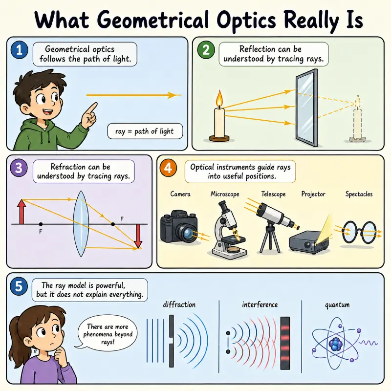
This educational comic introduces geometrical optics as a practical way to study light by following its path. It shows that a ray is a useful line representing the path of light, not a physical thread. The comic illustrates how reflection can be understood by tracing rays from a candle to a mirror, how refraction can be studied using ray diagrams through a lens, and how optical instruments such as cameras, microscopes, telescopes, projectors, and spectacles guide light into useful positions. It also reminds students that the ray model is powerful but limited, since diffraction, interference, and quantum effects require deeper models of light.
How Geometrical Optics Fits within Light and Optics
Geometrical optics sits inside the wider study of light and optics. It focuses on reflection, refraction, image formation, optical instruments, and practical optical design. These ideas prepare students for more advanced topics such as wave optics, lasers, optical fibres, photonics, imaging systems, and visual optics.
Light and Optics
Provides the wider foundation for studying how light travels, reflects, refracts, forms images, behaves as a wave, and supports modern optical technologies.Geometrical Optics
Current module. Uses rays, straight-line paths, reflection, and refraction to explain how images are formed by mirrors, lenses, and optical instruments.Wave Optics
Extends the study of light beyond rays into interference, diffraction, polarisation, and the wave nature of light.Six Main Pathways through This Hub
This hub is organised around six connected sub-pages. Each one explores a major part of geometrical optics. Together, they show how simple ray ideas become a complete framework for understanding mirrors, lenses, refraction, image formation, optical instruments, and real-world optical imperfections. Use the links below to explore the cluster subpages:
Reflection and Plane Mirrors
Introduces the law of reflection and explains how flat mirrors form upright virtual images behind the mirror.Refraction and Snell’s Law
Explains how light changes direction when it enters a new medium and how Snell’s Law predicts the refracted angle.Lenses and Image Formation
Shows how converging and diverging lenses form real and virtual images through controlled refraction.Mirrors and Image Formation
Extends reflection from plane mirrors to concave and convex mirrors, including real images, virtual images, magnification, and field of view.Optical Instruments
Applies geometrical optics to cameras, microscopes, telescopes, projectors, spectacles, contact lenses, magnifying glasses, and the human eye.Aberrations and Optical Design
Explains why real optical systems do not form perfect images and how designers reduce blur, colour error, distortion, and other defects.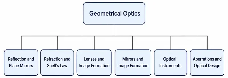
This clean tree chart presents Geometrical Optics as the head of the hub structure. Six connected sub-pages branch from it: Reflection and Plane Mirrors, Refraction and Snell’s Law, Lenses and Image Formation, Mirrors and Image Formation, Optical Instruments, and Aberrations and Optical Design. The chart helps students see how the major topics in geometrical optics are organised into a clear learning pathway, from basic reflection and refraction to image formation, optical instruments, and real-world optical design.
Core Ideas Students Should Understand
The topics in geometrical optics may look separate at first, but they are built from a small number of recurring ideas. Once these ideas become familiar, ray diagrams, mirror problems, lens problems, and optical instruments become much easier to connect.
Light Travels in Straight Lines in a Uniform Medium: In a uniform medium such as air, water, or glass, light can often be represented by straight rays. This allows us to use geometry to predict where light travels, where it meets a surface, and how it reaches the eye, a screen, or a sensor.
Reflection Changes Direction at a Surface: When light reflects from a surface, the angle of incidence equals the angle of reflection. This simple rule explains how plane mirrors form images and how curved mirrors focus or spread light. It also supports reflective optical systems such as vehicle mirrors, shaving mirrors, searchlights, and reflecting telescopes.
Refraction Changes Direction at a Boundary: When light passes from one medium into another, its speed changes. If the light enters at an angle, its direction also changes. This is refraction. Snell’s Law connects the refractive indices of the two media with the angles measured from the normal. It explains why lenses focus light, why straws look bent in water, why prisms bend colours differently, and why optical fibres can guide light.
Images Form Where Rays Meet or Appear to Meet: A real image forms where actual rays meet. It can be projected onto a screen or sensor. A virtual image forms where rays only appear to come from when traced backward. Plane mirrors, convex mirrors, magnifying glasses, and some lens arrangements produce virtual images. This distinction is one of the central ideas of geometrical optics.
Curved Surfaces Control Convergence and Divergence: A curved mirror or lens can make rays converge, diverge, or appear to come from a different point. Concave mirrors and convex lenses can bring parallel rays toward a focus. Convex mirrors and concave lenses spread rays apart. This control of ray direction is the basis of many optical devices.
Optical Instruments Combine Simple Ideas for Practical Purposes: A real optical instrument rarely uses only one idea. A camera uses refraction, focusing, aperture control, and image formation. A microscope uses multiple lenses to magnify and resolve small structures. A telescope collects light and forms an image of distant objects. Spectacles correct the path of light before it enters the eye.
Interactive Core Idea Assessment
Quick Check: Core Ideas in Geometrical Optics
1. In a uniform medium such as still air or clear glass, how is light usually represented in geometrical optics?
A. As curved rays
B. As straight rays
C. As random paths
D. As circular loops
Answer: B. In a uniform medium, light is often represented by straight rays. This allows us to use geometry to predict where light travels and where it meets surfaces or reaches the eye, a screen, or a sensor.
2. What is the basic rule for reflection at a surface?
A. The angle of incidence is greater than the angle of reflection
B. The angle of incidence equals the angle of reflection
C. The reflected ray always follows the surface
D. The angle of reflection is always 90°
Answer: B. Reflection follows the rule θi = θr. The angle of incidence equals the angle of reflection, with both angles measured from the normal.
3. Why does light refract when it passes from one medium into another?
A. Because the new medium pulls the light sideways
B. Because the colour of light changes automatically
C. Because the speed of light changes, and the direction may change if it enters at an angle
D. Because all boundaries absorb part of the ray
Answer: C. Refraction happens because light changes speed when it enters a new medium. If it enters at an angle, its direction changes as well. This behaviour is described mathematically by Snell’s Law.
4. What is the difference between a real image and a virtual image?
A. A real image is brighter than a virtual image
B. A real image forms where rays actually meet, while a virtual image forms where rays only appear to come from
C. A virtual image can never be seen
D. A real image is always upright
Answer: B. A real image forms where actual rays meet and can be projected onto a screen or sensor. A virtual image forms where rays only appear to come from when traced backward.
5. Which optical components usually make parallel rays converge toward a focus?
A. Convex mirrors and concave lenses
B. Concave mirrors and convex lenses
C. Plane mirrors and prisms only
D. All curved surfaces always diverge rays
Answer: B. Concave mirrors and convex lenses can bring parallel rays toward a focus. Convex mirrors and concave lenses usually spread rays apart.
6. Why are optical instruments described as combinations of simple ideas?
A. Because they use only one lens or one mirror
B. Because they avoid image formation
C. Because they combine ideas such as refraction, reflection, focusing, aperture control, and image formation for practical use
D. Because all instruments work in exactly the same way
Answer: C. Optical instruments combine several core ideas. A camera, microscope, telescope, or pair of spectacles uses light control, focusing, and image formation in a purposeful way to produce a useful image.
7. Why is it helpful to learn these core ideas before studying complex optical instruments?
Because complex instruments are built from the same recurring ideas. Once you understand straight-line travel, reflection, refraction, image formation, and convergence or divergence, it becomes much easier to understand how microscopes, telescopes, cameras, and other devices work.
8. In Snell’s Law, from what line are the angles measured?
The angles are measured from the normal, which is the line drawn perpendicular to the boundary at the point where the ray meets it.
Key Equations and What They Tell Us
Equations in geometrical optics are useful, but they should not be treated as substitutes for understanding. A ray diagram explains the geometry. An equation helps calculate the size, location, or angle more precisely. The strongest understanding comes from using both together.
Law of Reflection: θi = θr. The angle of incidence equals the angle of reflection, with both angles measured from the normal.
Refractive Index: n = c / v. A larger refractive index means light travels more slowly in that medium.
Snell’s Law: n1 sin θ1 = n2 sin θ2. This predicts how much a ray bends when it enters a new medium.
Critical Angle: sin θc = n2 / n1, where n1 > n2. This gives the limiting angle for total internal reflection.
Mirror and Lens Equations: Relate focal length, object distance, and image distance. They are best understood together with ray diagrams and a clear sign convention.
Magnification: Compares image size with object size. It helps describe whether an image is enlarged, diminished, upright, or inverted.
Ray Transfer Matrix Analysis (ABCD Matrix Mechanics)
While simple geometric equations adequately track single thin lenses, multi-element optical systems—such as telephoto camera lenses and laser resonators—require a scalable linear algebra framework. Ray Transfer Matrix Analysis, commonly known as ABCD matrix mechanics, models light rays as vectors tracking two primary parameters: vertical distance from the optical axis (y) and the propagation trajectory angle (θ) relative to that axis.
In the paraxial approximation, where angles are small enough that sin θ ≈ θ, the transformation of a ray passing through an optical element is governed by matrix multiplication:
$$
\begin{bmatrix} y_2 \\ \theta_2 \end{bmatrix} = \begin{bmatrix} A & B \\ C & D \end{bmatrix} \begin{bmatrix} y_1 \\ \theta_1 \end{bmatrix}
$$Each basic geometric transition possesses its own characteristic matrix properties. For example, a ray traveling a distance d through a homogeneous medium is defined by a translation matrix where A = 1, B = d, C = 0, and D = 1. Conversely, a ray refracting through a thin lens of focal length f alters its trajectory angle while maintaining its height, yielding a transformation matrix where A = 1, B = 0, C = −1 / f, and D = 1. By multiplying these independent element matrices sequentially from right to left, students can collapse an incredibly complex cascade of lenses and spaces down into a single composite system matrix, making it straightforward to isolate the definitive focal planes and entrance pupils of an entire multi-lens apparatus.
Practical ABCD Calculations and Interpretations
Example 1: Free Space Translation (Pure Distance Propagation)
Consider a light ray propagating through a uniform distance d = 100 mm in free space. The initial ray enters at a displacement height y1 = 5 mm above the optical axis with an upward slope trajectory angle θ1 = 0.02 rad. The matrix transformation is computed as:
$$
\begin{bmatrix} y_2 \\ \theta_2 \end{bmatrix} = \begin{bmatrix} 1 & 100 \\ 0 & 1 \end{bmatrix} \begin{bmatrix} 5 \\ 0.02 \end{bmatrix} = \begin{bmatrix} 1(5) + 100(0.02) \\ 0(5) + 1(0.02) \end{bmatrix} = \begin{bmatrix} 7 \\ 0.02 \end{bmatrix}
$$Interpretation: The resulting values show that the output height y2 increases to 7 mm because the ray travels along an upward slope. The output angle θ2 remains exactly 0.02 rad, confirming that light paths maintain a constant trajectory angle when traveling through a uniform, homogeneous medium without boundary interfaces.
Example 2: Thin Converging Lens Refraction
Consider a light ray striking a thin converging lens with a focal length f = 50 mm. The ray enters perfectly parallel to the main optical axis at a displacement height y1 = 10 mm, meaning its initial trajectory angle θ1 = 0 rad. The matrix transformation is computed as:
$$
\begin{bmatrix} y_2 \\ \theta_2 \end{bmatrix} = \begin{bmatrix} 1 & 0 \\ -\frac{1}{50} & 1 \end{bmatrix} \begin{bmatrix} 10 \\ 0 \end{bmatrix} = \begin{bmatrix} 1(10) + 0(0) \\ -\frac{1}{50}(10) + 1(0) \end{bmatrix} = \begin{bmatrix} 10 \\ -0.2 \end{bmatrix}
$$Interpretation: The resulting height y2 stays at 10 mm because a thin lens alters a ray’s velocity and direction without adding a physical translation distance. The output angle θ2 shifts to −0.2 rad; the negative sign means the ray is bent downward, turning inward to converge toward the primary focal point down the axis.
From Ideal Ray Diagrams to Real Optical Systems
In classroom diagrams, rays are usually clean, thin, and perfectly controlled. Mirrors and lenses are often treated as ideal. Real optical systems are more complicated. Lenses have thickness, materials have dispersion, surfaces are not perfectly simple, and off-axis rays may behave differently from central rays.
This is why the study of aberrations and optical design is important. Real cameras, microscopes, telescopes, projectors, spectacles, and imaging systems must control not only where rays meet, but also how sharp, bright, accurate, and useful the resulting image is.
A good optical system is therefore not merely one that bends light. It is one that bends light in a controlled way for a specific purpose. The goal may be clearer vision, higher magnification, wider field of view, better contrast, lower distortion, greater brightness, or more accurate measurement.
Common Misconceptions in Geometrical Optics
Geometrical optics is often introduced with simple diagrams, so misconceptions can easily remain hidden. Clearing them early helps students avoid confusion when moving from plane mirrors to curved mirrors, lenses, optical instruments, and optical design.
Ray Modeling Scope
Misconception: Rays are physical strings or real baseline structures of light. Reality: A ray is a geometric model showing the trajectory of light energy travel. It does not illustrate structural wave features like diffraction or quantum photon states.Virtual Image Validity
Misconception: Virtual images are “fake” illusions that cannot be viewed by the eye. Reality: Virtual images are entirely visible. The difference is that real rays do not physically focus at the virtual image spot; they only appear to diverge from it when tracked backward.Angular Calculations
Misconception: Reflection and refraction angles are calculated relative to the boundary surface layout. Reality: All ray tracking angles are strictly measured relative to the normal line, which runs perpendicular to the interface surface.Interactive Misconception Assessment
Quick Check: Common Misconceptions in Geometrical Optics
1. Which statement best describes a ray in geometrical optics?
A. A physical thread that carries light
B. A model showing the direction of light travel
C. A surface that reflects light
D. A wave that replaces all other models of light
Answer: B. A ray is a model that shows the direction in which light travels. It is very useful in geometrical optics, but it is not a physical string or the complete nature of light.
2. Which statement about virtual images is correct?
A. Virtual images are fake and cannot be seen
B. Virtual images can be seen, but actual rays do not meet at the image position
C. Virtual images can only be formed by lenses
D. Virtual images are always upside down
Answer: B. A virtual image is still visible to the eye. The difference is that the light rays do not actually meet at the image position. Instead, they only appear to come from that position when traced backward.
3. Why is “more magnification” not always enough in an optical system?
A. Because magnification always reduces brightness
B. Because a larger image is useful only if it is also sharp, bright, and resolved
C. Because magnification matters only in mirrors
D. Because magnification removes all aberrations
Answer: B. Magnification alone is not enough. A bigger image is only helpful if the instrument also provides enough sharpness, brightness, and resolution to reveal useful detail.
4. In reflection and refraction, from where are angles measured?
A. From the surface itself
B. From the top of the object
C. From the normal
D. From the focal point
Answer: C. Angles of incidence, reflection, and refraction are measured from the normal, which is the line drawn perpendicular to the surface at the point where the ray meets it.
5. What is the best description of the relationship between equations and ray diagrams?
A. Equations replace ray diagrams completely
B. Ray diagrams replace equations completely
C. Equations calculate results, while ray diagrams explain the geometry behind them
D. They are unrelated tools
Answer: C. Equations help calculate image distance, magnification, and angles, but ray diagrams show why the result makes sense geometrically. The two approaches work best together.
6. Which statement about real optical systems is most accurate?
A. Real lenses and mirrors always form perfect images
B. Optical design is unnecessary if the equation is correct
C. Real optical systems may show blur, distortion, colour error, and off-axis defects
D. Only cheap optical systems have imperfections
Answer: C. Real optical systems are not perfect. Even well-designed lenses and mirrors can show blur, distortion, colour fringes, or off-axis defects. Optical design works to reduce these limitations as much as possible.
Why Study Geometrical Optics?
Geometrical optics is worth studying because it connects simple physics with many technologies that people use every day. It also trains students to think visually, geometrically, and practically.
Visual Reasoning Skills
Ray diagrams teach students how simple geometric lines explain complex behaviors like magnification, image inversion, and field of view limitations.Everyday Infrastructure Physics
Provides core explanations for common optical observations, such as shallow-looking swimming pools, bent straws, magnifying glasses, and prescription lenses.Foundations of Engineering
Bridges classical physical rules with complex technical choices involving material refractive indices, system brightness values, and production costs.Wave Optics Transition
Establishing solid intuition for straight-line ray approximations helps students appreciate the transitions into higher-level wave diffraction models.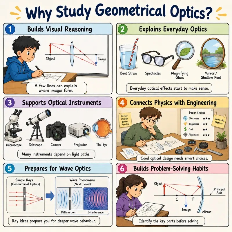
This educational comic explains why geometrical optics is useful for students. It shows how ray diagrams build visual reasoning, how everyday effects such as bent straws, spectacles, magnifying glasses, mirrors, and shallow-looking pools become easier to understand, and how optical instruments such as microscopes, telescopes, cameras, projectors, and the eye depend on light paths. It also connects optics with engineering design choices such as sharpness, brightness, cost, and alignment, while showing that ray ideas prepare students for deeper wave-optics topics such as diffraction and interference. The final panel highlights the importance of identifying key parts of an optical problem before solving it.
Fermat’s Principle, Phase Velocity, and Wavefront Aberrations
To connect abstract geometric ray approximations with the underlying physical laws of optics, students must understand Fermat’s Principle of Least Time. This fundamental theorem states that a ray of light traveling between two stationary points chooses a path that minimizes the total optical path length (OPL), mathematically defined as the integral of the local refractive index along the physical trajectory path:
$$
\text{OPL} = \int_{P_1}^{P_2} n(s) \, ds
$$This path minimization parameter provides the exact physical derivation for Snell’s Law and the law of reflection. In an idealized imaging system, all rays emerging from an object point must possess identical optical path lengths to their corresponding image point, maintaining perfectly spherical phase fronts.
In real physical systems, however, structural deviations occur. Geometrical shapes—such as standard spherical lenses—fail to focus marginal rays at the exact spatial point as paraxial rays. This geometric discrepancy creates wavefront aberrations, traditionally classified via Seidel polynomial expressions into distinct categories: spherical aberration, coma, astigmatism, field curvature, and distortion. Analyzing these wavefront deformations through Fermat’s framework allows university-bound students to look past idealized illustrations and gain insight into how precision optical engineering shapes aspheric profiles to eliminate structural image blurring.
Glossary
- Ray
- A geometric line used to model the directional path along which light energy travels.
- Normal
- An imaginary reference line constructed perpendicular to a boundary interface at the point of ray incidence.
- Reflection
- The turning back of a light wavefront at an interface boundary layer without changing its propagation medium.
- Refraction
- The boundary directional bending of a light path caused by changes in propagation velocity between two differing media.
- Refractive Index
- A dimensionless ratio mapping the velocity of light inside a vacuum relative to its phase velocity inside a target medium.
- Real Image
- An optical image focused by actual intersecting rays that can be projected directly onto a physical sensor plane or screen.
- Virtual Image
- An image positioned where diverging light paths appear to intersect when traced backward, viewable by the eye but unprojectable onto a screen.
Analytical Exercise Questions and Suggested Answers
The following questions help students review the main ideas in geometrical optics and connect the ray model of light with reflection, refraction, image formation, optical instruments, and optical design.
1. What is geometrical optics?
Answer: Geometrical optics is the study of light using rays. A ray is a line that represents the direction in which light travels. This model helps us understand reflection, refraction, mirrors, lenses, image formation, and optical instruments without starting from the full wave nature of light.
2. Why do we use the ray model of light?
Answer: The ray model makes light easier to visualise. In many everyday situations, light travels in straight-line paths until it meets a mirror, lens, surface, or boundary between two materials. By drawing rays, we can predict where light goes and where an image forms.
3. Does geometrical optics explain everything about light?
Answer: No. Geometrical optics is a powerful model, but it does not explain all optical effects. Diffraction, interference, polarisation, and some colour effects require the wave model of light. Geometrical optics works best when objects, openings, mirrors, and lenses are much larger than the wavelength of light.
4. What does it mean to say that light travels in straight lines?
Answer: It means that in a uniform medium, such as still air or clear glass, light can often be represented as travelling along straight paths. This helps explain sharp shadows, mirror images, lens diagrams, and the apparent position of objects seen through optical systems.
5. What is the normal in ray diagrams?
Answer: The normal is an imaginary line drawn perpendicular to a surface or boundary at the point where a ray meets it. Angles of incidence, reflection, and refraction are measured from the normal, not from the surface.
6. What is reflection?
Answer: Reflection occurs when light bounces from a surface. In geometrical optics, the angle of incidence equals the angle of reflection: θi = θr. This rule explains how plane mirrors, concave mirrors, convex mirrors, and reflecting instruments guide light.
7. Why do plane mirrors form virtual images?
Answer: A plane mirror reflects light so that the reflected rays appear to come from behind the mirror. The eye traces these reflected rays backward and sees an image behind the mirror. Since the actual rays do not meet behind the mirror, the image is virtual.
8. What is refraction?
Answer: Refraction occurs when light passes from one medium into another and changes speed. If the light enters at an angle, it changes direction. This explains effects such as a bent-looking straw in water, the apparent depth of a pool, lens focusing, prisms, and optical fibres.
9. What is Snell’s Law?
Answer: Snell’s Law relates the angle of incidence, the angle of refraction, and the refractive indices of the two media: n1 sin θ1 = n2 sin θ2. It is used to calculate how much a ray bends when it passes from one material into another.
10. What is refractive index?
Answer: Refractive index is a number that describes how much a medium slows light compared with its speed in vacuum: n = c / v. A higher refractive index means light travels more slowly in that medium.
11. What is total internal reflection?
Answer: Total internal reflection occurs when light travels from a higher-index medium to a lower-index medium and reaches the boundary at an angle greater than the critical angle. Instead of refracting out, the light reflects completely back into the original medium.
12. What is the difference between a real image and a virtual image?
Answer: A real image forms where actual light rays meet. It can be projected onto a screen or sensor. A virtual image forms where rays only appear to come from when traced backward. It cannot be projected directly onto a screen, but it can still be seen by the eye.
13. How do lenses form images?
Answer: Lenses form images by refraction. A converging lens can bring rays together to form a real image, or it can form a virtual magnified image when the object is close to the lens. A diverging lens spreads rays apart and usually forms a virtual, upright, diminished image.
14. How do curved mirrors form images?
Answer: Curved mirrors form images by reflection. A concave mirror can bring reflected rays together and may form real or virtual images depending on object position. A convex mirror spreads reflected rays apart and usually forms a virtual, upright, reduced image with a wider field of view.
15. Why are ray diagrams important?
Answer: Ray diagrams show the geometry behind image formation. They help students identify whether an image is real or virtual, upright or inverted, magnified or reduced. Equations calculate values, but ray diagrams explain the meaning of the result.
16. Do equations replace ray diagrams?
Answer: No. Equations and ray diagrams work best together. A ray diagram helps students understand the optical geometry, while an equation helps calculate image distance, magnification, refracted angle, or critical angle more precisely.
17. What are optical instruments?
Answer: Optical instruments are devices that guide light to help us see, record, project, magnify, correct, or measure images. Cameras, microscopes, telescopes, projectors, spectacles, contact lenses, magnifying glasses, and the human eye can all be understood using geometrical optics.
18. What are optical aberrations?
Answer: Optical aberrations are imperfections in image formation. Real lenses and mirrors may produce blur, colour fringes, distortion, or uneven sharpness. Optical design reduces these problems by choosing suitable shapes, materials, lens combinations, apertures, coatings, and alignments.
19. Why are real optical systems more complicated than simple ray diagrams?
Answer: Simple ray diagrams often assume ideal mirrors, thin lenses, small angles, and perfect alignment. Real optical systems have thickness, material properties, surface curvature, aperture limits, dispersion, and manufacturing constraints. These factors affect sharpness, brightness, distortion, and image quality.
20. Why is geometrical optics useful for students?
Answer: Geometrical optics builds visual reasoning and connects physics with everyday experience. It explains mirror images, bent straws, spectacles, cameras, projectors, microscopes, telescopes, and optical fibres. It also prepares students for wave optics, optical engineering, imaging technology, photonics, and vision science.
21. What is the best way to study geometrical optics?
Answer: A good method is to begin with the physical situation, identify the object, surface, normal, focal point, and likely image type, then draw the rays carefully. After that, use the relevant equation to calculate image position, magnification, angle of refraction, or critical angle.
22. What is the most important idea to remember about geometrical optics?
Answer: The central idea is that light can be guided. Mirrors guide light by reflection, lenses guide light by refraction, and optical instruments combine these effects to form useful images. Geometrical optics helps us understand where light goes, where images form, and how optical devices are designed.
Frequently Asked Questions: Geometrical Optics
1. What is geometrical optics?
Geometrical optics is the study of light using rays. A ray is a line that shows the direction in which light travels. This model helps us understand reflection, refraction, mirrors, lenses, image formation, and many optical instruments without beginning with the full wave nature of light.
2. Why do we use rays to study light?
Rays make light behaviour easier to visualise. In many everyday situations, light travels in straight-line paths until it meets a surface, mirror, lens, or boundary between two materials. By drawing rays, students can predict where light goes and where an image forms.
3. Does geometrical optics explain everything about light?
No. Geometrical optics is a useful model, but it does not explain all light behaviour. Effects such as diffraction, interference, polarisation, and some colour phenomena require the wave model of light. Geometrical optics is strongest when mirrors, lenses, openings, and objects are much larger than the wavelength of light.
4. What is reflection in geometrical optics?
Reflection occurs when light bounces from a surface. In ray diagrams, the angle of incidence equals the angle of reflection, with both angles measured from the normal. This rule explains how plane mirrors, concave mirrors, convex mirrors, and many reflecting instruments guide light.
5. What is refraction?
Refraction occurs when light passes from one medium into another and changes speed. If the light enters the new medium at an angle, its direction changes. This bending of light explains why a straw appears bent in water, why lenses focus light, and why prisms and optical fibres work.
6. What is Snell’s Law used for?
Snell’s Law is used to calculate how much a ray bends when it passes between two materials: n1 sin θ1 = n2 sin θ2. It connects the refractive indices of the two media with the angles of incidence and refraction. Both angles are measured from the normal, not from the surface.
7. What is the difference between a real image and a virtual image?
A real image forms where actual light light rays meet. It can be projected onto a screen or sensor. A virtual image forms where rays only appear to come from when traced backward. It cannot be projected directly onto a screen, but it can still be seen by the eye.
8. Why do plane mirrors form virtual images?
A plane mirror reflects light so that the reflected rays spread out in front of the mirror. When the eye traces those rays backward, they appear to come from a point behind the mirror. This is why the image appears behind the mirror even though no light actually passes through that position.
9. How do curved mirrors form different kinds of images?
Curved mirrors change the direction of reflected rays in different ways. A concave mirror can bring rays together and may form real or virtual images depending on the object position. A convex mirror spreads rays apart and usually forms a virtual, upright, diminished image with a wider field of view.
10. How do lenses form images?
Lenses form images by refraction. A converging lens can bring rays together to form real images, or it can form a virtual magnified image when the object is close to the lens. A diverging lens spreads rays apart and usually forms a virtual, upright, diminished image.
11. Why are ray diagrams important?
Ray diagrams show the geometry behind image formation. They help students see whether an image is real or virtual, upright or inverted, magnified or diminished. Equations can calculate image distances and sizes, but ray diagrams explain what the calculation means.
12. What are optical instruments?
Optical instruments are devices that guide light to help us see, record, magnify, project, or measure images. Cameras, microscopes, telescopes, projectors, spectacles, contact lenses, magnifying glasses, and the human eye can all be understood using geometrical optics.
13. What are optical aberrations?
Optical aberrations are imperfections in image formation. Real lenses and mirrors may produce blur, colour fringes, distortion, or uneven sharpness across the image. Optical design reduces these defects by carefully choosing shapes, materials, lens combinations, apertures, coatings, and alignments.
14. Why is geometrical optics useful for students?
Geometrical optics builds strong visual reasoning. It helps students understand everyday effects such as mirror images, bent straws, spectacles, camera focusing, magnification, and image projection. It also prepares students for later topics such as wave optics, optical engineering, imaging technology, photonics, and vision science.
15. What is the best way to study geometrical optics?
The best approach is to combine ray diagrams, physical reasoning, and equations. First identify the object, surface, normal, focal point, and likely image type. Then draw the rays carefully. Finally, use the relevant equation to calculate the image position, magnification, angle, or critical condition.
External References
These references provide additional explanations of reflection, refraction, lenses, mirrors, image formation, and optical instruments.
Summary
Geometrical optics studies light by tracing rays. This model helps explain reflection, refraction, mirrors, lenses, image formation, and optical instruments. It is simple enough for beginners, but powerful enough to support real applications in cameras, microscopes, telescopes, projectors, spectacles, optical fibres, and imaging systems.
The key idea is that light can be guided. A mirror changes its direction by reflection. A lens changes its direction by refraction. Curved surfaces cause rays to converge or diverge. Images form where rays meet or appear to meet. Optical instruments combine these ideas to help people see, record, magnify, project, correct, and measure.
This hub prepares students to study each part of geometrical optics in more detail: reflection and plane mirrors, refraction and Snell’s Law, lenses and image formation, mirrors and image formation, optical instruments, and aberrations and optical design.
Reflection Question
If a ray diagram can explain where light appears to come from, what does that tell us about the way the eye, a camera, or a microscope interprets the path of light?