Prepare for University Studies & Career Advancement
Polarization of Light
Polarization of light describes the direction in which the electric field of a light wave oscillates. Ordinary light often contains waves vibrating in many directions perpendicular to the direction of travel. Polarized light is more ordered: its electric field vibrations have a preferred direction or pattern. This idea is central to Wave Optics because polarization reveals that light is a transverse electromagnetic wave.
When students first meet light, they often focus on reflection, refraction, lenses, and image formation. Polarization adds a deeper wave-based view. It shows that light is not only moving forward; it is also oscillating sideways. This sideways oscillation can be filtered, rotated, reflected, scattered, delayed, and analysed. These effects explain polarized sunglasses, liquid-crystal displays, stress analysis in transparent materials, 3D cinema, optical communication, and scientific instruments.
This page sits within the wider study of Light and Optics, which functions as a structural core inside the broader field of physical science. It connects naturally with reflection, refraction, interference, diffraction, electromagnetic waves, optical fibres, and modern imaging technologies. The main goal is to help students see polarization not as an isolated fact, but as one of the clearest pieces of evidence that light behaves as a transverse wave.
Explore the Wave Optics Cluster
Polarization is best understood alongside the other core wave behaviors of light. You can explore the complete pathway through the following subpages:
Explains how stable phase relationships support macro-scale wave overlap for high-precision distance metrology.
Polarization of Light
Current page. Explore the directional nature of transverse oscillations, filtering properties, and electro-optic modulation mechanisms.
What Polarization of Light Really Is
Light is an electromagnetic wave. Its electric field and magnetic field oscillate perpendicular to each other and perpendicular to the direction in which the wave travels. In most optical discussions, the polarization direction refers to the direction of the electric field oscillation.
For unpolarized light, the electric field does not vibrate in just one fixed direction. Instead, many waves are present with different vibration directions. Sunlight, ordinary lamp light, and most everyday light sources are approximately unpolarized. By contrast, linearly polarized light has an electric field that oscillates along one preferred direction.
A polarizing filter works by allowing one component of the electric field to pass while absorbing or blocking the perpendicular component. This is why two polarizing filters can strongly reduce transmitted light when their transmission axes are crossed at right angles. The first filter selects one vibration direction; the second filter may block it if its axis is perpendicular.
Why Polarization Proves Light Is Transverse
Polarization is possible because light is a transverse wave. In a transverse wave, the disturbance oscillates perpendicular to the direction of travel. A wave travelling forward can therefore have different sideways vibration directions. These different directions can be selected by a polarizer.
Longitudinal waves, such as ordinary sound waves in air, do not show polarization in the same way because their oscillations occur along the direction of travel. There is no separate sideways vibration direction to filter. This is why polarization is such an important concept in wave optics: it gives direct physical evidence that light has transverse wave behaviour.
In electromagnetic language, a light wave travelling in the x-direction may have its electric field oscillating in the y-direction, the z-direction, or in a combination of both. The direction and phase relationship of these components determine whether the light is linearly, circularly, or elliptically polarized.
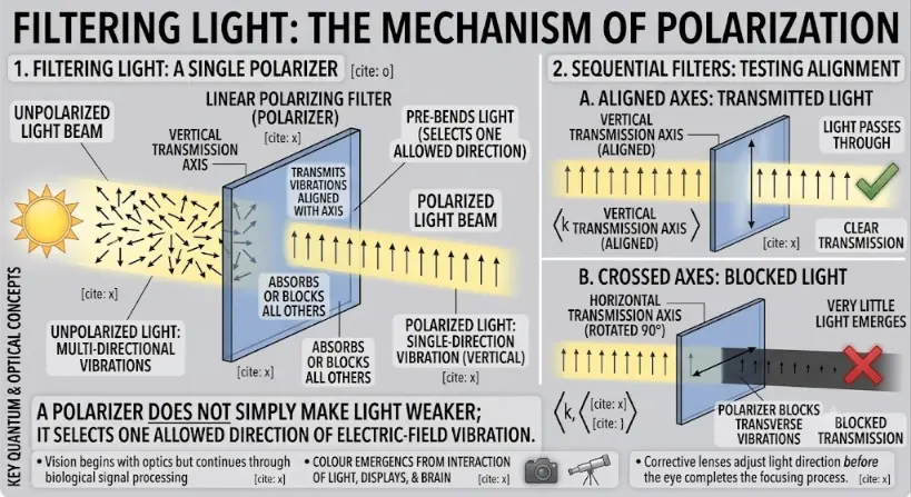
The optical mechanism of a linear polarizing filter. The infographic shows that a polarizer filters multi-directional light vibrations not by simply attenuating the energy uniformly, but by physically absorbing unaligned transverse oscillations and selectively transmitting only the component aligned with its transmission axis.
The image is a comprehensive technical infographic titled “FILTERING LIGHT: THE MECHANISM OF POLARIZATION”. The layout uses clean, diagrammatic lines, bright yellow light beams, and blue-tinted filter rectangles on a gray background to map how light behaves when interacting with physical polarizers.
Part 1: Filtering Light: A Single Polarizer
The large panel on the left side of the graphic models the action of an individual polarizing element:
Unpolarized Light Input: A cartoon sun on the far left acts as the light source, emitting a yellow light beam labeled “UNPOLARIZED LIGHT BEAM”. Inside this beam before the filter, the text highlights “UNPOLARIZED LIGHT: MULTI-DIRECTIONAL VIBRATIONS” accompanied by a chaotic clutter of arrows pointing outwards in many different transverse directions.
The Linear Filter: The unpolarized beam encounters a translucent blue rectangular sheet labeled “LINEAR POLARIZING FILTER (POLARIZER)” that features a marked “VERTICAL TRANSMISSION AXIS”. Text annotations clarify that it “TRANSMITS VIBRATIONS ALIGNED WITH AXIS” and “ABSORBS OR BLOCKS ALL OTHERS”.
Polarized Light Output: Emerging from the other side of the filter is a clean, uniform yellow stream labeled “POLARIZED LIGHT BEAM”. The arrows inside this section are strictly orderly, pointing uniformly upwards to demonstrate “POLARIZED LIGHT: SINGLE-DIRECTION VIBRATION (VERTICAL)”.
A prominent bold banner at the bottom of this panel summarizes the physical concept: “A POLARIZER DOES NOT SIMPLY MAKE LIGHT WEAKER; IT SELECTS ONE ALLOWED DIRECTION OF ELECTRIC-FIELD VIBRATION.”
Part 2: Sequential Filters: Testing Alignment
The panel on the right half is divided vertically into two sub-scenarios testing the alignment of a secondary filter placed in series:
A. Aligned Axes: Transmitted Light: The top sub-panel shows an incoming beam of vertically polarized light (represented by vertical arrows) hitting a second blue polarizer whose axis is also configured vertically (“VERTICAL TRANSMISSION AXIS – ALIGNED”). The light waves pass cleanly through without changing orientation, labeled “LIGHT PASSES THROUGH” and “CLEAR TRANSMISSION”, marked by a prominent green checkmark.
B. Crossed Axes: Blocked Light: The bottom sub-panel shows the exact same vertically polarized light hitting a second blue polarizer that has been turned sideways (“HORIZONTAL TRANSMISSION AXIS – ROTATED 90°”). Because the vertical field vibrations are orthogonal to the horizontal structure, the filter absorbs the light. The downstream beam turns into an empty, dark gray shadow labeled “VERY LITTLE LIGHT EMERGES” and “BLOCKED TRANSMISSION”, marked by a large red “X”.
Infographic Layout Context
The very bottom margin of the canvas contains boilerplate text rows and decorative camera/telescope icons inherited from an underlying layout template, which mention unrelated peripheral optics concepts (such as biological signal processing and corrective lenses). The core visual narrative is successfully driven by the primary polarization sections described above.
The Evolutionary Path: History, System Barriers, and Foundry Paradigms
The active management of light synchronization transformed optical measurements from raw intensity tracking into high-resolution spatial mapping across shared physical coordinates.
The Historical Journey
The structural discovery of polarization traces back to 1669, when Erasmus Bartholin observed double refraction (birefringence) through a crystal of Iceland spar. In 1808, Étienne-Louis Malus verified that unpolarized light can be organized through simple surface reflection, leading directly to his formulation of the cosine-squared intensity rules. By 1812, David Brewster quantified the exact angle where reflection yields perfectly polarized light fields based on refraction indices. The manufacturing layer evolved significantly in 1928, when Edwin Land synthesized micro-crystals embedded in thin sheet polymers, building the first cost-effective commercial linear polarizer filters (Polaroids) and establishing the foundations for display foundries.
Contemporary Technical Hurdles
The primary boundary in processing modern micro-display architectures is managing extinction ratios and thermal degradation parameters. When stacking organic liquid crystal layers and polarizer meshes inside high-brightness arrays, the blocking filter layer is forced to absorb enormous quantities of unaligned light energy. This localized absorption converts straight into high thermal energy, elevating component temperatures. If the system exceeds strict operating thresholds, the chemical layout of the polymer filter warps or bleaches, leaking un-targeted field components, reducing image contrast ratios, and introducing color-shifting artifacts across localized display coordinates.
Future Paradigms: Wire-Grid Micro-Polarizers and Nanophotonic Routing
Advanced fabrication cleanrooms bypass organic heat degradation and macro thickness boundaries by etching metallic sub-wavelength wire configurations and waveplates straight onto solid state platforms:
Aluminum Wire-Grid Micro-Polarizer Arrays: To achieve heat-resistant polarization filtering inside high-luminance projectors, modern silicon foundries print arrays of sub-wavelength metallic lines using deep lithography tracks. These micro-thin grids act as miniature wire boundaries that reflect unaligned electric-field oscillations rather than absorbing them, eliminating thermal breakdown while sustaining strict extinction profiles across broad temperature arcs.
Integrated Semiconductor Form-Factor Waveplates: Next-generation communication foundries are processing birefringent gallium arsenide and silicon-on-insulator structures to modulate spatial field channels right on a processor chip. These nanoscale phase arrays route orthogonal polarization tracks across distinct on-chip logic gates, driving ultra-fast multiplexed signals for data centers without requiring separate external bulk crystals.
Main Types of Polarization
Linear Polarization
In linear polarization, the electric field oscillates back and forth along one fixed line. For example, the field may vibrate vertically while the wave travels horizontally. Linear polarization is the simplest and most commonly introduced form of polarization.
A linear polarizer produces linearly polarized light by transmitting the component of the electric field parallel to its transmission axis and blocking the perpendicular component. This behaviour is often described using Malus’s law.
Circular Polarization
In circular polarization, the electric field maintains a constant magnitude but rotates as the wave travels. At a fixed point in space, the tip of the electric-field vector traces a circle over time. Circular polarization can be right-handed or left-handed depending on the direction of rotation.
Circular polarization can be produced by combining two perpendicular electric-field components of equal amplitude with a phase difference of 90°, or 0.5\(\pi\) radians.
Elliptical Polarization
In elliptical polarization, the electric-field vector traces an ellipse. This is the most general form of polarization. Linear and circular polarization can be viewed as special cases of elliptical polarization.
Elliptical polarization occurs when two perpendicular field components have different amplitudes, or when their phase relationship is not exactly the special case needed for circular polarization.
Polarization by Transmission Through a Polarizer
A polarizing filter has a transmission axis. Only the component of the electric field parallel to this axis is transmitted. The component perpendicular to the axis is mostly absorbed or blocked. If unpolarized light enters an ideal polarizer, the transmitted intensity is reduced to about half of the original intensity:
$$I = \frac{1}{2}I_0$$
This happens because unpolarized light contains many vibration directions. On average, only half of its intensity lies along the transmission direction of the polarizer.
After the first polarizer, the light is linearly polarized along the transmission axis. If it then passes through a second polarizer, called an analyser, the transmitted intensity depends on the angle between the polarization direction and the analyser axis.
Malus’s Law
Malus’s law describes how the intensity of linearly polarized light changes after passing through a polarizing analyser. If the angle between the light’s polarization direction and the analyser’s transmission axis is \(\theta\), then:
$$I = I_0 \cos^2 \theta$$
Here, I0 is the intensity of the incident linearly polarized light, and I is the transmitted intensity. When \(\theta\) = 0°, the axes are aligned and the transmitted intensity is maximum. When \(\theta\) = 90°, the axes are crossed and ideally no light is transmitted.
Angle Between Polarizers
\(\cos^2 \theta\)
Transmitted Intensity
Meaning
0°
1
I = I0
Axes aligned; maximum transmission
30°
0.75
I = 0.75I0
Most of the polarized light passes through
45°
0.50
I = 0.50I0
Half of the polarized light passes through
60°
0.25
I = 0.25I0
Only one-quarter passes through
90°
0
I = 0
Crossed polarizers; ideal extinction
Polarization by Reflection
Light can become partially polarized when it reflects from a non-metallic surface such as glass, water, or a polished road. This is why glare from horizontal surfaces can be reduced using polarized sunglasses. The reflected light tends to have a strong horizontal polarization component, and vertically oriented polarizing lenses can block much of it.
At a special angle called Brewster’s angle, the reflected light is completely polarized. Brewster’s law is:
$$\tan \theta_{\mathrm{B}} = \frac{n_2}{n_1}$$
Here, \(\theta_{\mathrm{B}}\) is Brewster’s angle, n1 is the refractive index of the first medium, and n2 is the refractive index of the second medium. At this angle, the reflected and refracted rays are perpendicular to each other.
Polarization by reflection is important in photography, outdoor vision, optical instruments, glare reduction, and the study of reflective surfaces.
Polarization by Scattering
Scattering can also polarize light. When sunlight enters Earth’s atmosphere, molecules and small particles scatter light in different directions. The scattered light from the sky is partially polarized, especially at directions roughly perpendicular to the Sun’s position.
This is why polarizing filters can darken parts of the blue sky in photography. The effect depends on where the camera is pointed relative to the Sun. It also shows that polarization is not only a laboratory phenomenon; it appears naturally in the atmosphere.
Polarization by Birefringence
Some materials are birefringent. This means they have different refractive indices for different polarization directions. When light enters such a material, it can split into two rays with different speeds and different polarization states.
Birefringence is important in crystals such as calcite, in liquid crystals, and in stressed transparent materials. Engineers and scientists can use polarized light to study stress patterns inside transparent plastics, glass, and mechanical components.
In optical devices, birefringent materials can be used to create wave plates. A quarter-wave plate can help convert linearly polarized light into circularly polarized light, while a half-wave plate can rotate the direction of linear polarization.
Polarization and Electromagnetic Waves
In classical physics, light is an electromagnetic wave. Its electric and magnetic fields oscillate together while energy travels through space. If the wave travels along the x-direction, the electric field may oscillate along the y-direction while the magnetic field oscillates along the z-direction.
The electric field is usually used to define the polarization because it interacts strongly with charges in matter. Polarizing materials work by responding differently to different electric-field directions. This is why polarization is closely connected with molecular structure, crystal symmetry, and the electromagnetic nature of light.
Applications of Polarization
Polarized Sunglasses
Polarized sunglasses reduce glare from horizontal surfaces such as water, roads, and snow. They are especially useful because reflected glare is often strongly horizontally polarized. The lenses are designed to block this polarization direction while allowing more useful light to pass.
Photography and Imaging
Photographers use polarizing filters to reduce reflections from glass or water, darken parts of the sky, and improve contrast. The effect depends on the angle of the light source, the reflecting surface, and the filter orientation.
Liquid-Crystal Displays
Liquid-crystal displays use polarization to control brightness. Liquid-crystal molecules can rotate the polarization of light depending on an applied voltage. Combined with polarizing filters, this allows pixels to appear bright or dark.
3D Cinema
Some 3D cinema systems use different polarization states for the left-eye and right-eye images. The glasses allow each eye to receive the intended image, helping the brain construct a sense of depth.
Stress Analysis
Transparent materials under stress can become optically anisotropic, meaning their optical properties depend on direction. When placed between polarizers, stress patterns may appear as coloured or bright-dark regions. This is useful in engineering analysis and material testing.
Optical Communication
In advanced optical systems, polarization can affect signal quality. Fibre-optic communication, lasers, modulators, and detectors may need careful control of polarization to reduce distortion, loss, or unwanted interference effects.
Astronomy and Remote Sensing
Polarization measurements help scientists study scattering by dust, magnetic fields, planetary atmospheres, and reflective surfaces. In astronomy and remote sensing, polarization can reveal information that ordinary intensity measurements may miss.
Common Misunderstandings About Polarization
Misunderstanding 1: Polarization means the light travels in only one direction. Polarization describes the direction of electric-field vibration, not the direction of the beam’s travel.
Misunderstanding 2: A polarizer simply dims light like a grey filter. A polarizer selects one vibration direction. The dimming occurs because some electric-field components are blocked.
Misunderstanding 3: Only lasers can be polarized. Lasers are often polarized, but ordinary light can also be polarized by filters, reflection, scattering, or birefringent materials.
Misunderstanding 4: Crossed polarizers always block all light perfectly. Ideal crossed polarizers block all transmitted light, but real polarizers may leak a small amount.
Misunderstanding 5: Polarization is unrelated to everyday life. Polarization appears in sunglasses, screens, photography, 3D cinema, stress analysis, fibre optics, and atmospheric light scattering.
Connections with Wider Wave Optics
Polarization belongs naturally within wave optics because it depends on the wave nature of light. It complements other wave phenomena such as interference, diffraction, coherence, and dispersion. While interference and diffraction reveal how waves overlap and spread, polarization reveals the sideways structure of the electromagnetic wave itself.
The parent cluster for studying light as a wave, including interference, diffraction, coherence, polarization, and related optical phenomena.
Polarization of Light
The current page, focusing on the direction of electric-field oscillation and how light can be filtered, reflected, scattered, or analysed by polarization.
Learning Pathway: From Wave Direction to Polarization
A good learning pathway begins with the idea that light is a transverse electromagnetic wave. Once students understand that the electric field vibrates sideways, polarization becomes easier to understand. The next step is to see how polarizers select one vibration direction, how Malus’s law predicts transmitted intensity, and how reflection, scattering, and birefringent materials can produce or change polarization.
Learning Step
Main Idea
What Students Should Notice
1
Light is transverse
The electric field oscillates perpendicular to the direction of travel.
2
Unpolarized light has many vibration directions
Ordinary light usually contains many possible transverse electric-field directions.
3
A polarizer selects one direction
Only the field component along the transmission axis passes through.
4
Two polarizers reveal Malus’s law
Transmitted intensity depends on \(\cos^2 \theta\).
5
Reflection, scattering, and birefringence can polarize light
Polarization occurs naturally and in useful optical devices.
Quick Check: Polarization of Light
Quick Check: Polarization of Light
Q1. What does polarization describe?
Polarization describes the direction or pattern of the electric-field oscillation in a light wave.
Q2. Why does polarization show that light is a transverse wave?
Polarization depends on sideways vibration directions. Since light can have different transverse electric-field directions, it shows that light behaves as a transverse wave.
Q3. What happens when linearly polarized light passes through an analyser at 90°?
Ideally, no light is transmitted because the analyser axis is perpendicular to the polarization direction.
Q4. Why do polarized sunglasses reduce glare?
Glare from horizontal surfaces is often strongly horizontally polarized. Polarized sunglasses block much of this component, reducing reflected glare.
Q5. What does Malus’s law predict?
Malus’s law predicts how much intensity passes through an analyser when linearly polarized light meets it at an angle.
Key Terms
Birefringence
The property of a material having different refractive indices for different polarization directions.
Brewster’s angle
The angle of incidence at which reflected light from a surface is completely polarized.
Circularly polarized light
Light whose electric-field vector rotates with constant magnitude as the wave travels.
Elliptically polarized light
Light whose electric-field vector traces an ellipse.
Linearly polarized light
Light whose electric field oscillates along one fixed direction.
Malus’s law
The law \(I = I_0 \cos^2 \theta\), describing the transmitted intensity through an analyser.
Polarization
The direction or pattern of electric-field oscillation in a light wave.
Polarizer
An optical filter that transmits one electric-field component and blocks the perpendicular component.
Analyser
A second polarizer used to test or measure the polarization direction of light.
Transmission axis
The direction along which a polarizer allows the electric-field component to pass.
Unpolarized light
Light containing many electric-field vibration directions with no single preferred direction.
Wave plate
An optical device that changes the phase relationship between polarization components.
Frequently Asked Questions: Polarization of Light
1. What is polarization of light?
Polarization of light describes the direction or pattern of the electric-field oscillation in a light wave. It is a wave property that helps show light is transverse.
2. Is ordinary sunlight polarized?
Direct sunlight is usually treated as unpolarized because it contains many electric-field vibration directions. However, sunlight can become partially polarized after scattering in the atmosphere or reflecting from surfaces.
3. What does a polarizing filter do?
A polarizing filter transmits the electric-field component along its transmission axis and blocks much of the perpendicular component. This produces or analyses linearly polarized light.
4. What is Malus’s law?
Malus’s law states that the transmitted intensity of linearly polarized light through an analyser is \(I = I_0 \cos^2 \theta\), where \(\theta\) is the angle between the polarization direction and the analyser axis.
5. Why do crossed polarizers block light?
The first polarizer transmits light along one direction. If the second polarizer is turned 90°, its transmission axis is perpendicular to that direction, so ideally it blocks the light.
6. How do polarized sunglasses work?
Polarized sunglasses reduce glare by blocking strongly polarized reflected light, especially glare from horizontal surfaces such as water, roads, and snow.
7. What is Brewster’s angle?
Brewster’s angle is the angle of incidence at which reflected light from a non-metallic surface becomes completely polarized. It satisfies \(\tan \theta_{\mathrm{B}} = n_2/n_1\).
8. What is birefringence?
Birefringence occurs when a material has different refractive indices for different polarization directions. It can split light into two rays and is useful in crystals, wave plates, liquid crystals, and stress analysis.
9. Can polarization happen naturally?
Yes. Natural polarization can occur through reflection, scattering in the atmosphere, and interaction with certain crystals or materials.
10. Why is polarization important in modern technology?
Polarization is used in sunglasses, cameras, LCD screens, 3D cinema, optical communication, stress analysis, microscopy, astronomy, remote sensing, and many scientific instruments.
Review Questions and Answers
What does polarization describe in a light wave?
Answer: Polarization describes the direction or pattern of oscillation of the electric field in the light wave.
Why is polarization evidence that light is transverse?
Answer: Polarization depends on the direction of sideways electric-field oscillation. This is possible for transverse waves, where the disturbance is perpendicular to the direction of travel.
What is unpolarized light?
Answer: Unpolarized light contains many electric-field vibration directions and has no single preferred polarization direction.
What happens when unpolarized light passes through an ideal polarizer?
Answer: The transmitted light becomes linearly polarized, and its intensity is reduced to about half the original intensity.
State Malus’s law.
Answer: Malus’s law is \(I = I_0 \cos^2 \theta\), where \(\theta\) is the angle between the light’s polarization direction and the analyser axis.
What happens when two ideal polarizers are crossed at 90°?
Answer: Ideally, no light is transmitted because the second polarizer blocks the polarization direction passed by the first.
How can reflection produce polarization?
Answer: Light reflected from a non-metallic surface can become partially polarized. At Brewster’s angle, the reflected light is completely polarized.
Why is the sky partially polarized?
Answer: Sunlight scattered by molecules and particles in the atmosphere becomes partially polarized, especially at directions roughly perpendicular to the Sun.
What is birefringence?
Answer: Birefringence is the property of a material having different refractive indices for different polarization directions.
Name two everyday applications of polarization.
Answer: Two common applications are polarized sunglasses and liquid-crystal displays. Other examples include photography filters, 3D cinema, and stress analysis.
Thought-Provoking Questions and Answers
Why does polarization reveal something about the structure of light that ordinary brightness does not?
Answer: Brightness tells us how much energy is being carried, but polarization tells us how the electric field is oriented. It reveals the internal transverse structure of the wave.
Why might a polarizing filter improve a photograph of water but not remove every reflection?
Answer: Reflections may be only partially polarized, and the amount of polarization depends on angle, surface type, and lighting conditions. A polarizer can reduce selected glare but cannot remove all reflected light in every situation.
Why are crossed polarizers useful in scientific instruments?
Answer: Crossed polarizers create a dark background unless a material between them changes the polarization. This makes birefringence, stress patterns, and crystal structures easier to observe.
How does polarization show that waves can carry more information than just intensity and wavelength?
Answer: Polarization adds another degree of freedom. A light wave can carry information in its amplitude, frequency, phase, direction, and polarization state.
Why might polarization become important in advanced optical communication?
Answer: Polarization can affect signal propagation, loss, and interference. It can also be used as an additional property for encoding, filtering, or controlling optical signals.
Comprehensive Numerical Problems with Solutions
Unpolarized light holding an intensity of 80 W/m² encounters an idealized linear polarizing element. Calculate the output beam intensity.
Solution:
When unpolarized light streams through an ideal linear polarizer, exactly half of the initial energy component aligns with the allowed transmission axis:
$$I = \frac{1}{2}I_0$$
Substitute the coordinate value directly into the calculation:
$$I = \frac{1}{2} \times 80 = 40\text{ W/m}^2$$
Answer: The transmitted light intensity measures exactly 40 W/m².
A linearly polarized ray with an initial intensity tracking at 100 W/m² arrives at an optical analyzer configured at an offset angle of 30°. Find the net transmitted intensity.
Solution:
Apply Malus’s law:
$$I = I_0 \cos^2 \theta$$
Substitute the field parameters into the layout model (I0 = 100 W/m², \(\theta\) = 30°):
$$I = 100 \times \cos^2(30^\circ)$$
Since \(\cos(30^\circ) = \frac{\sqrt{3}}{2} \approx 0.8660\), squaring it yields precisely 0.7500:
$$I = 100 \times 0.75 = 75\text{ W/m}^2$$
Answer: The transmitted vector intensity measures exactly 75 W/m².
Linearly polarized light maintaining an initial intensity parameter of 60 W/m² strikes a analyzer oriented at a 60° boundary. Determine the emerging intensity.
Solution:
Use Malus’s cosine-squared modulation expression:
$$I = I_0 \cos^2 \theta$$
Substitute metrics straight into the equation layout:
$$I = 60 \times \cos^2(60^\circ)$$
Since \(\cos(60^\circ) = 0.5000\), its squared modulation factor drops exactly to 0.2500:
$$I = 60 \times 0.25 = 15\text{ W/m}^2$$
Answer: The emerging transmission intensity measures exactly 15 W/m².
An unpolarized light beam possessing an initial intensity of 120 W/m² passes sequentially through a linear polarizer and then an analyzer locked at a 45° relative offset axis. Calculate the final system intensity.
Solution:
1. Find the intermediate polarization field energy after the initial component slice:
2. Apply Malus’s field translation rule to find the output profile after the secondary analyzer:
$$I_2 = I_1 \cos^2(45^\circ)$$
Since \(\cos(45^\circ) = \frac{1}{\sqrt{2}} \approx 0.7071\), its squared attenuation product equals exactly 0.5000:
$$I_2 = 60 \times 0.50 = 30\text{ W/m}^2$$
Answer: The final exit intensity balances precisely at 30 W/m².
Compute the precise value of Brewster’s angle for a boundary layer transition tracking from air into a dense glass block holding a refractive index parameter of 1.50. Assume n1 = 1.00 and n2 = 1.50.
Solution:
Apply Brewster’s angular index equation:
$$\tan \theta_{\mathrm{B}} = \frac{n_2}{n_1}$$
Substitute values to isolate the tangent function coordinate:
Answer: Brewster’s complete polarization angle tracks at approximately 56.3°.
A specialized monochromatic tracking beam is totally blocked by an absolute analyzer. Use Malus’s metrics to solve the exact angular offset coordinate setting separating the beam vector from the analyzer axis.
Solution:
For an ideal system to achieve complete field extinction, the output transmission intensity parameter must drop to absolute zero:
$$I = I_0 \cos^2 \theta = 0$$
This state structurally dictates that the isolated cosine function resolves to zero:
$$\cos \theta = 0$$
Taking the inverse arc-cosine isolates the exact perpendicular angular arrangement:
$$\theta = \cos^{-1}(0) = 90^\circ$$
Answer: The analyzer axis aligns at exactly 90° (orthogonal) relative to the incoming polarization field vector.
Why This Topic Matters
Polarization matters because it reveals that light has a directional wave structure, not just brightness and colour. It allows students to see light as an electromagnetic wave with an oscillating electric field. This insight supports later study of optics, electromagnetic waves, lasers, fibre optics, imaging, displays, materials testing, and modern photonics.
The topic is also practical. Polarization explains familiar technologies such as sunglasses, LCD screens, camera filters, and 3D cinema. At a deeper level, it supports scientific tools used in microscopy, astronomy, material stress analysis, remote sensing, and communication systems. A student who understands polarization gains a more complete and more modern understanding of light.
Summary
Polarization of light describes the direction or pattern of electric-field oscillation in a light wave. It is possible because light is a transverse electromagnetic wave. Unpolarized light contains many vibration directions, while polarized light has a more ordered electric-field pattern.
Polarization can be produced by transmission through polarizers, reflection, scattering, and birefringent materials. Malus’s law describes how the transmitted intensity depends on the angle between a linearly polarized beam and an analyser. Brewster’s law describes the special angle at which reflected light becomes completely polarized.
By studying polarization, students connect wave optics with everyday technology, scientific instruments, and the electromagnetic nature of light. The subject shows that light waves carry not only energy and wavelength, but also direction and structure within their oscillating fields.
Reflection Question
If two beams of light have the same colour and intensity, but different polarization states, what does that tell us about the hidden structure of light waves?