
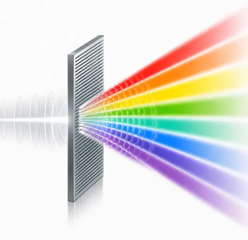
Diffraction gratings are optical structures that use many closely spaced lines, grooves, or slits to separate light into different directions according to wavelength. When light meets a grating, each opening or groove acts as a source of diffracted waves. These waves overlap and interfere, producing bright directions where the waves reinforce one another strongly.
This page belongs to the wider study of wave optics, where light is described using wavelength, phase, amplitude, interference, diffraction, polarization, and coherence. Diffraction gratings connect directly with interference of light because a grating pattern is created by constructive and destructive interference from many regularly spaced sources. They also build on diffraction and resolution, because the sharpness of grating spectra depends on how wave spreading and interference work together.
Diffraction gratings are important because they turn the wave nature of light into a practical measuring tool. A beam of white light can be split into a spectrum. A mixture of unknown wavelengths can be analysed. Light from stars, lamps, lasers, atoms, and materials can be studied by observing where the diffracted bright lines appear. In this sense, a diffraction grating is not just a piece of patterned material. It is a ruler for wavelength.
Learning Pathway: Where Diffraction Gratings Fit in Wave Optics
Diffraction gratings sit near the point where wave optics becomes a powerful tool for measurement. Single-slit diffraction shows how light spreads. Interference shows how waves reinforce or cancel. A diffraction grating combines both ideas through many regularly spaced openings or grooves, producing sharp directions of constructive interference.
Light and Optics
Introduces how light travels, reflects, refracts, forms images, behaves as a wave, and interacts with materials.Wave Optics
Studies light through wavelength, phase, interference, diffraction, polarization, coherence, and wave behaviour.Interference of Light
Explains how overlapping light waves reinforce or cancel one another to produce bright and dark patterns.Diffraction and Resolution
Shows how light spreads through openings and why optical instruments have physical limits to sharpness.Thin-Film Interference
Applies interference to soap bubbles, oil films, coatings, and coloured reflections from thin layers.Polarization of Light
Explains how light waves can have a preferred direction of vibration and how this affects optical systems.Diffraction Gratings
Shows how many closely spaced lines or openings separate light into spectra and allow wavelength to be measured.Coherence and Interferometry
Explains why stable phase relationships matter and how interference fringes can be used for precision measurement.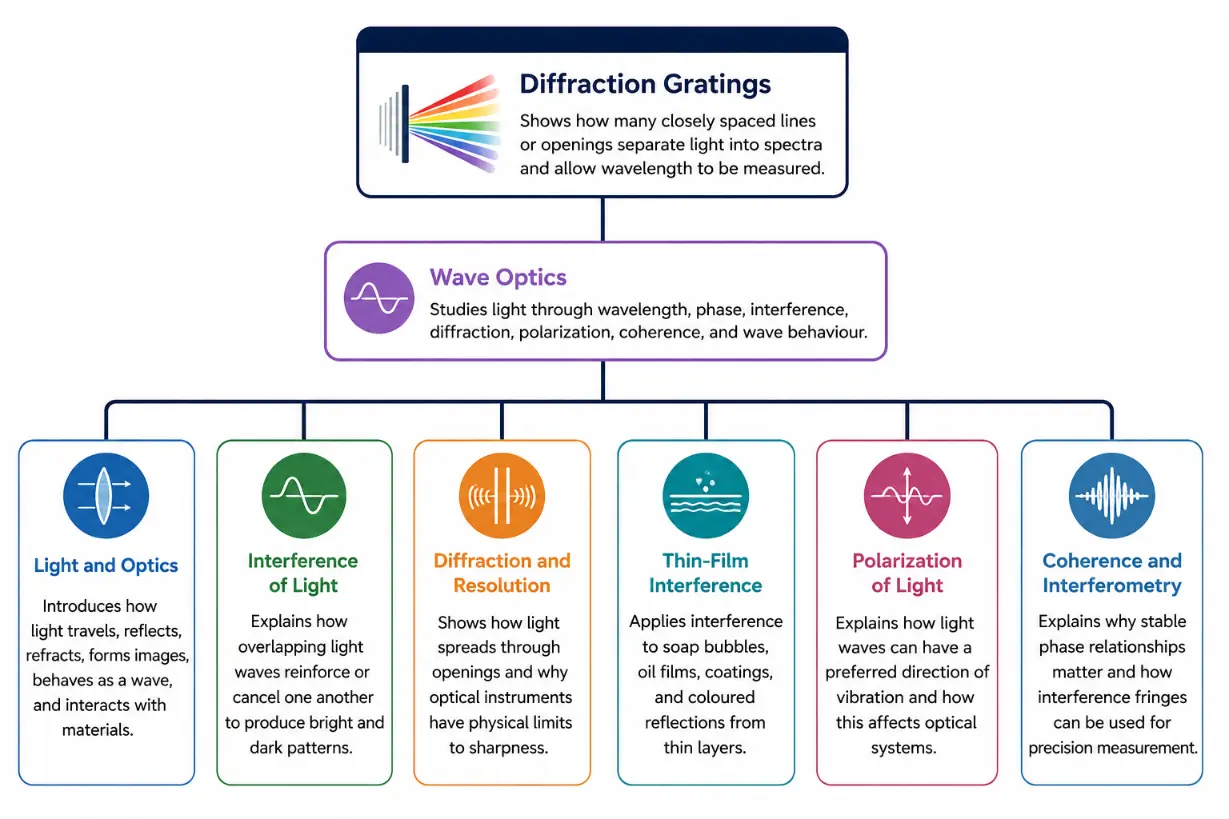
This diagram presents Diffraction Gratings as part of the wider Wave Optics cluster. It shows how the topic builds on the behaviour of light as a wave, especially interference and diffraction. Related pages include Light and Optics, Interference of Light, Diffraction and Resolution, Thin-Film Interference, Polarization of Light, and Coherence and Interferometry. The structure helps students see that diffraction gratings are not an isolated topic. They are a natural extension of wave optics, using many closely spaced lines or openings to separate light into spectra and measure wavelength.
What Diffraction Gratings REALLY Mean
A diffraction grating is an optical element with many equally spaced lines, grooves, or slits. The spacing between neighbouring lines or openings is called the grating spacing, usually written as \( d \). When light meets the grating, it is diffracted by each line or opening. The diffracted waves then overlap and interfere.
The important difference between a single slit and a grating is the number of contributing sources. A single slit involves interference among many parts of one aperture. A diffraction grating involves interference from many regularly spaced openings or grooves. Because the spacing is regular, the reinforcement happens in very specific directions. This produces sharp bright maxima rather than broad, vague spreading.
A grating therefore acts like an organised crowd of wave sources. If the waves from neighbouring openings arrive in phase in a particular direction, their effects add strongly and produce a bright line. If they arrive out of phase, they cancel. This is why gratings can separate wavelengths with great precision.
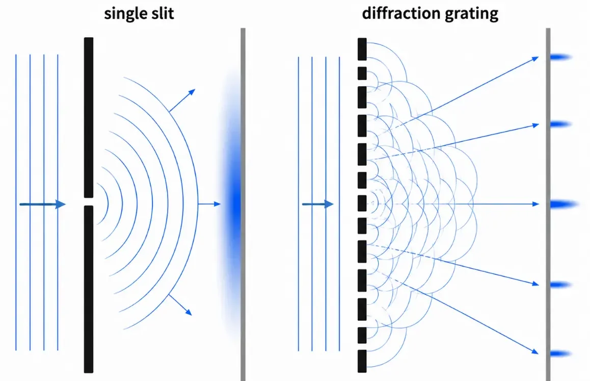
This diagram compares the behaviour of light passing through a single slit with light passing through a diffraction grating. On the left, one narrow slit acts as a single aperture, causing the transmitted wavefront to spread broadly and form a wide diffraction pattern. On the right, many regularly spaced openings act as multiple wave sources. Their diffracted waves overlap and reinforce only in selected directions, producing sharper bright maxima on the screen. The comparison helps students understand why diffraction gratings can separate wavelengths more precisely than a single slit.
Transmission and Reflection Gratings
Diffraction gratings can work in two common ways. A transmission grating allows light to pass through many fine openings or transparent regions. A reflection grating has many fine grooves on a reflective surface, so light reflects from the patterned surface and interferes.
The basic wave idea is the same in both cases. Light from neighbouring grating lines or openings travels different distances before reaching an observation direction. If the path difference matches a whole number of wavelengths, the waves reinforce and a bright diffracted beam appears.
Many classroom diagrams show transmission gratings because they are easier to visualise. Many practical spectrometers use reflection gratings because they can be made with precise grooves and used efficiently in compact optical instruments.
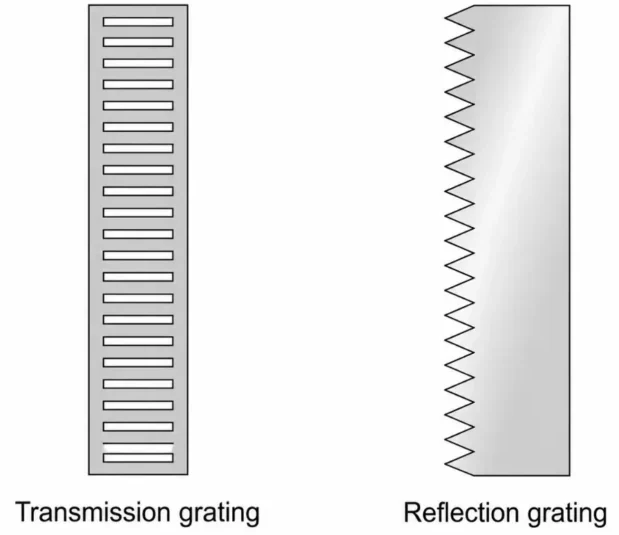
This simple diagram compares the physical structure of two common types of diffraction gratings. The transmission grating is shown as a flat plate with many narrow slits or transparent openings through which light can pass. The reflection grating is shown as a reflective surface with a repeated serrated groove structure. The image focuses only on the structural difference between the two gratings, without showing light rays, so students can first understand what each grating looks like before studying how diffraction and interference occur.
How a Diffraction Grating Works
To understand a diffraction grating, imagine monochromatic light falling on a grating with equally spaced openings. Each opening sends out diffracted waves. At a point far away, waves from neighbouring openings may arrive with a path difference.
If the path difference is exactly one wavelength, two wavelengths, three wavelengths, and so on, the waves arrive in phase. Their crests meet crests, and their troughs meet troughs. This gives constructive interference, forming a bright diffracted direction.
If the path difference is not a whole number of wavelengths, waves from the many openings do not all reinforce. Their contributions cancel partly or strongly, producing much lower intensity. With many openings, the cancellation away from the main bright directions becomes very effective, so the bright lines become narrow and well defined.
This is the power of a grating. A few slits can produce interference fringes. Many slits produce much sharper maxima. The more regularly spaced openings or grooves there are, the more precisely the grating can direct and separate light.
Quick Check: Why Many Lines Matter
Question 1: Why does a diffraction grating produce sharper bright lines than two slits?
A grating has many regularly spaced openings or grooves. In the correct directions, light from all of them reinforces strongly. In most other directions, many contributions cancel. This makes the bright maxima narrow and sharp.
Question 2: What must happen for a bright grating maximum to appear?
The path difference between light from neighbouring grating lines must be a whole number of wavelengths, so the waves arrive in phase and reinforce.
Question 3: Why are the dark regions between grating maxima usually very dark?
With many openings or grooves, waves that are not in the correct phase relationship cancel very effectively. This makes the regions between the bright maxima much weaker.
The Grating Equation
For normal incidence, the main condition for bright maxima from a diffraction grating is:
\( d\sin\theta = m\lambda \)
where \( d \) is the spacing between neighbouring grating lines or slits, \( \theta \) is the angle of the diffracted maximum measured from the central direction, \( m \) is the order of the maximum, and \( \lambda \) is the wavelength of light.
The integer \( m \) can take values such as \( 0, 1, 2, 3, \ldots \). The central maximum has \( m = 0 \), so \( \theta = 0 \). The first-order maximum has \( m = 1 \). The second-order maximum has \( m = 2 \), and so on, as long as the equation can physically be satisfied.
Because \( \sin\theta \) cannot be greater than 1, not all orders are possible. The highest possible order depends on the ratio between grating spacing and wavelength.
What the Grating Equation Means
The equation \( d\sin\theta = m\lambda \) says that the path difference between waves from neighbouring grating lines must equal a whole number of wavelengths. This condition is very similar in spirit to double-slit interference, but the large number of grating lines makes the bright directions much sharper.
For a fixed grating spacing, longer wavelengths are diffracted to larger angles. This is why red light is usually sent farther from the central direction than blue light in a given order. A diffraction grating can therefore separate white light into colours.
Grating Spacing and Line Density
Gratings are often described by the number of lines per unit length. For example, a grating may have \( 500 \) lines per millimetre, \( 600 \) lines per millimetre, or \( 1200 \) lines per millimetre. The more lines there are per millimetre, the smaller the spacing \( d \) between neighbouring lines.
If the line density is \( N \) lines per metre, then the grating spacing is:
\( d = \frac{1}{N} \)
If the line density is given in lines per millimetre, it must first be converted into lines per metre before using SI units. Since \( 1 \ \text{mm} = 10^{-3} \ \text{m} \), a grating with \( 500 \) lines per millimetre has:
\( N = 500 \times 10^3 \ \text{lines m}^{-1} \)
Therefore:
\( d = \frac{1}{500 \times 10^3} = 2.0 \times 10^{-6} \ \text{m} \)
This spacing is only a few micrometres. Although this is much larger than a visible wavelength, it is small enough to produce strong angular separation between wavelengths.
Orders of Diffraction
The diffraction order \( m \) tells us which bright maximum is being considered. The zero-order maximum, \( m = 0 \), is the undeviated central beam. It usually contains all wavelengths together and is not separated into colours.
The first-order maxima, \( m = 1 \), appear on either side of the central beam. These are often the most useful for observing spectra because they are relatively bright and well separated. Higher orders such as \( m = 2 \) or \( m = 3 \) occur at larger angles if allowed by the grating equation.
For each order, different wavelengths appear at different angles. However, higher-order spectra can sometimes overlap with lower-order spectra of other wavelengths. This is an important practical issue in spectroscopy.
Maximum Possible Order
The grating equation also tells us whether a particular order can exist. Since \( \sin\theta \leq 1 \), we must have:
\( m\lambda \leq d \)
This means:
\( m \leq \frac{d}{\lambda} \)
The maximum possible order is the largest whole number that satisfies this condition. If the calculation gives \( 3.7 \), for example, the highest possible order is \( 3 \), not \( 4 \).
This condition is easy to forget, but it is physically important. If a required angle would need \( \sin\theta > 1 \), then that diffracted order cannot exist.
Worked Example: Finding the First-Order Angle
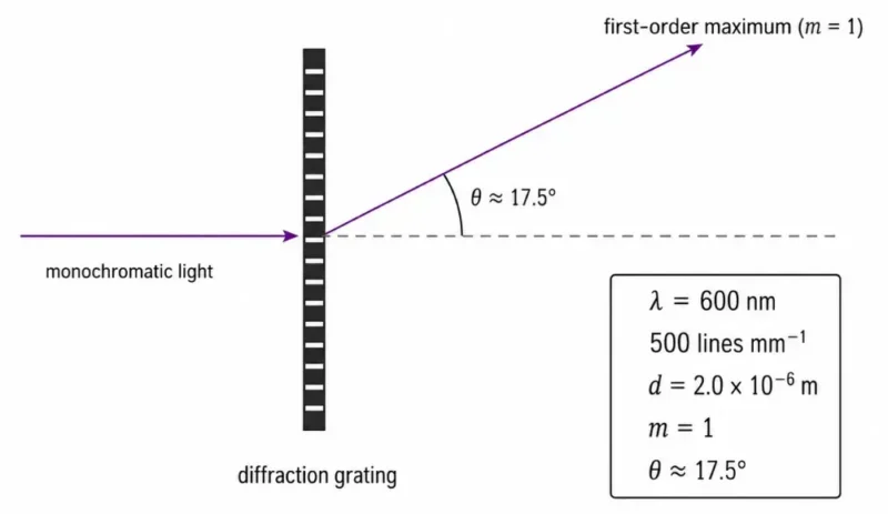
Problem: Monochromatic light of wavelength \( 600 \ \text{nm} \) falls normally on a diffraction grating with \( 500 \) lines per millimetre. Find the angle of the first-order maximum.
Solution:
First convert the line density into lines per metre:
\( N = 500 \times 10^3 \ \text{lines m}^{-1} \)
The grating spacing is:
\( d = \frac{1}{N} = \frac{1}{500 \times 10^3} \)
\( d = 2.0 \times 10^{-6} \ \text{m} \)
Use the grating equation:
\( d\sin\theta = m\lambda \)
For the first order, \( m = 1 \). Convert the wavelength:
\( \lambda = 600 \ \text{nm} = 600 \times 10^{-9} \ \text{m} \)
Substitute:
\( \sin\theta = \frac{m\lambda}{d} \)
\( \sin\theta = \frac{1(600 \times 10^{-9})}{2.0 \times 10^{-6}} \)
\( \sin\theta = 0.300 \)
Therefore:
\( \theta = \sin^{-1}(0.300) \)
\( \theta \approx 17.5^\circ \)
Interpretation: The first-order maximum appears at about \( 17.5^\circ \) from the central direction. A longer wavelength would appear at a larger angle for the same order.
Worked Example: Finding the Wavelength
Problem: A diffraction grating has spacing \( d = 1.67 \times 10^{-6} \ \text{m} \). A bright first-order line is observed at \( 20.0^\circ \). Find the wavelength of the light.
Solution:
Use the grating equation:
\( d\sin\theta = m\lambda \)
Rearrange for \( \lambda \):
\( \lambda = \frac{d\sin\theta}{m} \)
For first order, \( m = 1 \):
\( \lambda = \frac{(1.67 \times 10^{-6})\sin 20.0^\circ}{1} \)
\( \lambda = 5.71 \times 10^{-7} \ \text{m} \)
Therefore:
\( \lambda \approx 571 \ \text{nm} \)
Interpretation: This wavelength lies in the visible region, close to yellow-green light.
Worked Example: Maximum Order
Problem: Light of wavelength \( 500 \ \text{nm} \) is incident on a grating with spacing \( 2.0 \times 10^{-6} \ \text{m} \). Find the highest possible diffraction order.
Solution:
A diffraction order can exist only if:
\( m\lambda \leq d \)
So:
\( m \leq \frac{d}{\lambda} \)
Substitute:
\( d = 2.0 \times 10^{-6} \ \text{m} \)
\( \lambda = 500 \ \text{nm} = 500 \times 10^{-9} \ \text{m} \)
\( m \leq \frac{2.0 \times 10^{-6}}{500 \times 10^{-9}} \)
\( m \leq 4.0 \)
Therefore, the highest possible order is:
\( m = 4 \)
Interpretation: The fourth order is just possible because it would occur at \( \sin\theta = 1 \), corresponding to \( \theta = 90^\circ \). In real instruments, such an extreme direction may be difficult to observe practically.
Why Different Colours Separate
White light contains many wavelengths. When white light falls on a grating, each wavelength satisfies the grating equation at a different angle. Since the equation is \( d\sin\theta = m\lambda \), a larger wavelength needs a larger \( \sin\theta \) for the same order.
This means red light, with its longer wavelength, is diffracted to a larger angle than violet or blue light in the same order. The result is a spectrum: different colours appear in different directions.
The central maximum, \( m = 0 \), usually remains white because \( d\sin\theta = 0 \) gives \( \theta = 0 \) for all wavelengths. The separation of colours becomes visible in the non-zero orders, especially the first order.
Quick Check: Colour Separation
Question 1: Why does a grating separate white light into colours?
White light contains many wavelengths. Each wavelength satisfies \( d\sin\theta = m\lambda \) at a different angle, so different colours appear in different directions.
Question 2: In the first order, which is diffracted more strongly: red light or blue light?
Red light is diffracted to a larger angle because it has a longer wavelength than blue light.
Question 3: Why is the central maximum usually not separated into colours?
For the central maximum, \( m = 0 \), so \( d\sin\theta = 0 \). This gives \( \theta = 0 \) for all wavelengths, so the colours overlap in the central direction.
Angular Dispersion
A diffraction grating is useful because different wavelengths emerge at different angles. The ability of a grating to spread wavelengths apart angularly is called angular dispersion.
Greater angular dispersion means that a small difference in wavelength produces a larger difference in angle. This makes it easier to separate nearby spectral lines.
From the grating equation, shorter grating spacing \( d \) generally gives larger angular separation between wavelengths. This is why gratings with more lines per millimetre can produce more widely spread spectra, although practical limits such as overlapping orders and efficiency must also be considered.
Resolving Power of a Grating
The resolving power of a diffraction grating describes its ability to distinguish two wavelengths that are very close together. A grating with high resolving power can separate spectral lines that would otherwise appear merged.
A common expression for the resolving power of a grating is:
\( R = \frac{\lambda}{\Delta\lambda} = mN \)
where \( R \) is the resolving power, \( \lambda \) is the wavelength being observed, \( \Delta\lambda \) is the smallest wavelength difference that can be resolved, \( m \) is the order of diffraction, and \( N \) is the total number of illuminated grating lines.
This equation carries an important message. Resolving power improves when more grating lines are illuminated, and it also improves in higher diffraction orders. However, higher orders may be weaker or may overlap with other orders, so practical instrument design must balance several factors.
Worked Example: Resolving Power
Problem: A grating is used in second order, and \( 4000 \) grating lines are illuminated. Estimate the resolving power.
Solution:
Use:
\( R = mN \)
Here:
\( m = 2 \)
\( N = 4000 \)
Therefore:
\( R = 2(4000) \)
\( R = 8000 \)
Interpretation: The grating has a resolving power of \( 8000 \). This means it can distinguish wavelengths separated by about \( \frac{1}{8000} \) of the wavelength being observed, under ideal conditions.
Diffraction Gratings and Spectroscopy
One of the most important uses of diffraction gratings is spectroscopy. Spectroscopy studies light by separating it into wavelengths. Since atoms, molecules, stars, lamps, lasers, and materials emit or absorb particular wavelengths, a spectrum can reveal what a source is made of or what physical conditions it has experienced.
For example, glowing gases can produce bright emission lines at specific wavelengths. A grating can spread these wavelengths into separate directions, allowing the lines to be measured. Absorbing materials can remove certain wavelengths from a continuous spectrum, producing dark absorption lines. These patterns act like fingerprints of matter.
In astronomy, spectra reveal the composition, temperature, motion, and sometimes magnetic behaviour of stars and galaxies. In laboratories, spectra help identify elements, study materials, calibrate lasers, and measure unknown wavelengths.
Diffraction Grating Versus Prism
Both prisms and diffraction gratings can separate white light into colours, but they work by different physical principles. A prism separates colours because different wavelengths refract by different amounts inside the glass. This effect depends on the wavelength dependence of refractive index.
A diffraction grating separates colours by diffraction and interference. The grating equation determines the directions of constructive interference for different wavelengths.
A prism produces only one main spectrum for a given path, while a grating can produce multiple orders of spectra. Gratings are often preferred in spectroscopy because their wavelength behaviour can be described precisely by the grating equation and because they can provide high dispersion and resolving power.
| Feature | Prism | Diffraction Grating |
|---|---|---|
| Physical principle | Separates light by refraction | Separates light by diffraction and interference |
| Why colours separate | Different wavelengths refract by different amounts because the refractive index depends on wavelength | Different wavelengths satisfy the grating equation at different angles |
| Main equation | No single simple equation is usually used at this level; behaviour depends on refraction and dispersion in the material | dsinθ = mλ |
| Number of spectra | Usually produces one main spectrum for a given path | Can produce multiple orders of spectra |
| Dispersion | Can separate colours, but often with less control | Often provides high angular dispersion |
| Resolving power | Generally lower for precise wavelength separation | Often higher, especially with many lines and higher orders |
| Use in spectroscopy | Useful, but less common in high-precision modern spectroscopy | Widely preferred because wavelength behaviour is precise and measurable |
| Typical appearance of output | A single spread of colours | Sharp bright maxima and spectral orders |
Real-World Examples of Diffraction Gratings
Diffraction gratings are not limited to formal laboratory instruments. Similar effects can be seen when light reflects from finely spaced patterns. The shimmering colours on some optical discs, security holograms, and finely ruled surfaces arise because small regularly spaced structures separate wavelengths by interference.
In scientific instruments, gratings are carefully designed and manufactured so that the line spacing, groove profile, efficiency, and wavelength range are controlled. This turns a simple wave effect into a precise analytical tool.
Applications of Diffraction Gratings
Diffraction gratings are widely used because they can separate, measure, and analyse light with high precision. Their applications span physics, chemistry, astronomy, engineering, medicine, and communication technology.
Spectrometers
Spectrometers use diffraction gratings to separate incoming light into wavelengths. By measuring the angles or detector positions of spectral lines, the instrument can determine the wavelengths present in the source.
Astronomy
Astronomers use grating-based instruments to study light from stars, nebulae, galaxies, and quasars. Spectra reveal chemical composition, temperature, velocity through Doppler shifts, and other physical properties of distant objects.
Laser Wavelength Measurement
Diffraction gratings can be used to measure laser wavelength. A monochromatic laser produces sharp maxima at predictable angles, allowing \( \lambda \) to be calculated from \( d\sin\theta = m\lambda \).
Chemical and Material Analysis
Different atoms and molecules interact with light at specific wavelengths. Grating spectrometers help identify substances, measure concentrations, study plasmas, analyse materials, and monitor chemical processes.
Optical Communications
In optical communication systems, different wavelength channels may carry different data streams. Grating-based devices can help separate, combine, or select wavelengths in wavelength-division multiplexing systems.
Monochromators
A monochromator uses a grating to select a narrow range of wavelengths from a broader light source. This is useful in experiments where a controlled wavelength is needed.
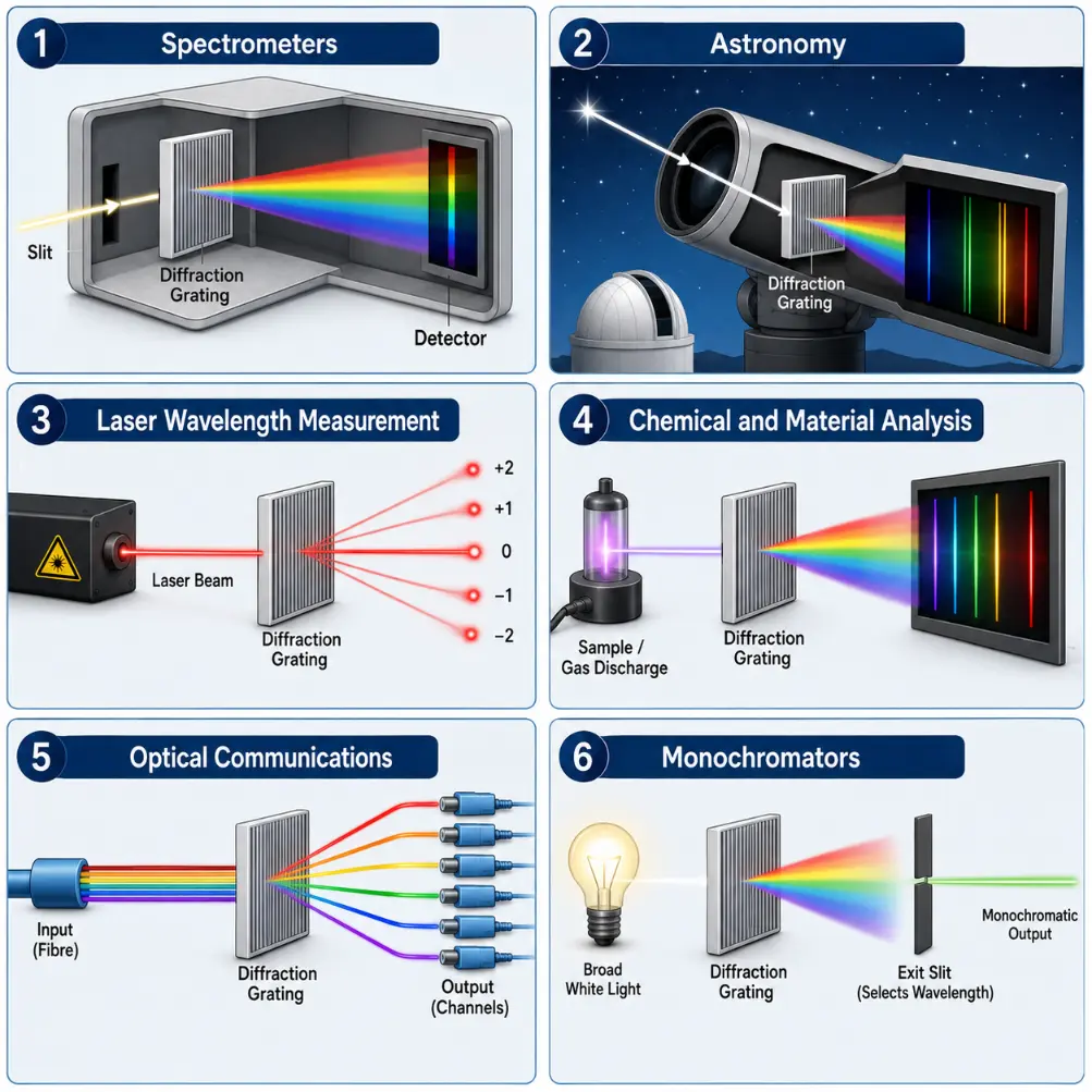
This infographic shows six important applications of diffraction gratings. In spectrometers, gratings separate incoming light into its component wavelengths so that spectral lines can be measured. In astronomy, grating-based instruments help scientists study the light from stars, nebulae, galaxies, and other distant objects. In laser wavelength measurement, a grating produces predictable diffraction orders that allow the wavelength of monochromatic light to be calculated. In chemical and material analysis, gratings help identify substances by separating characteristic emission or absorption lines. In optical communications, gratings can separate or combine different wavelength channels carrying data through fibres. In monochromators, a grating helps select one narrow wavelength range from a broader light source. Together, these examples show how diffraction gratings turn wave interference into a practical tool for analysing light.
Common Misconceptions About Diffraction Gratings
Misconception 1: A Grating Works Like a Coloured Filter
A filter selects or blocks wavelengths by absorption or transmission. A diffraction grating separates wavelengths by sending them into different directions through diffraction and interference. It does not simply colour the light.
Misconception 2: The Central Maximum Is the Main Spectrum
The central maximum is the zero-order beam. For white light, it usually remains white because all wavelengths overlap at \( \theta = 0 \). The separated spectra appear in non-zero orders such as \( m = 1 \) and \( m = 2 \).
Misconception 3: More Lines Always Make a Grating Better in Every Way
More lines can improve dispersion and resolving power, but practical performance also depends on wavelength range, grating efficiency, order overlap, groove shape, alignment, and detector design.
Misconception 4: Higher Orders Are Always Better
Higher orders can improve resolving power, but they may be weaker and may overlap with other orders. In real spectroscopy, the best order depends on the measurement goal and instrument design.
Misconception 5: A Diffraction Grating Is Just a More Complicated Prism
A prism separates light by refraction. A grating separates light by diffraction and interference. Both can produce spectra, but the underlying physics and practical behaviour are different.
Quick Check: Grating Misconceptions
Question 1: Does a diffraction grating separate colours by refraction like a prism?
No. A grating separates colours by diffraction and interference. A prism separates colours by wavelength-dependent refraction.
Question 2: Why is the zero-order maximum usually white for white light?
For \( m = 0 \), the grating equation gives \( \theta = 0 \) for all wavelengths. Since the colours overlap in the same direction, the central beam appears white.
Question 3: Why are higher diffraction orders not always the best choice?
Higher orders may improve resolving power, but they can be weaker and may overlap with other orders. Practical spectrometers must balance resolution, brightness, and order separation.
Study Tips for Diffraction Gratings
- Remember that the grating equation for normal incidence is \( d\sin\theta = m\lambda \).
- Convert line density carefully. Lines per millimetre must be converted into lines per metre before finding \( d \) in metres.
- Do not confuse grating spacing \( d \) with slit width. In grating problems, \( d \) is the distance between neighbouring grating lines or openings.
- The central maximum has \( m = 0 \), while first-order spectra have \( m = 1 \).
- Longer wavelengths appear at larger angles in the same diffraction order.
- Check whether a diffraction order is physically possible by remembering that \( \sin\theta \leq 1 \).
- For resolving power, remember that \( R = mN \), where \( N \) is the number of illuminated grating lines, not the line density.
Review Questions
Question 1: What is a diffraction grating?
Answer: A diffraction grating is an optical element with many closely spaced lines, grooves, or slits that diffract light and produce interference maxima in specific directions.
Question 2: What is the grating equation for normal incidence?
Answer: The grating equation is \( d\sin\theta = m\lambda \), where \( d \) is grating spacing, \( \theta \) is diffraction angle, \( m \) is order, and \( \lambda \) is wavelength.
Question 3: Why does a grating separate white light into colours?
Answer: Different wavelengths satisfy the grating equation at different angles. Therefore, each colour is diffracted into a different direction in a given order.
Question 4: What is the zero-order maximum?
Answer: The zero-order maximum is the central beam with \( m = 0 \). For white light, the colours overlap there, so it usually appears white.
Question 5: What does line density mean?
Answer: Line density is the number of grating lines per unit length. A higher line density means a smaller spacing \( d \) between neighbouring lines.
Question 6: Why can some diffraction orders be impossible?
Answer: A diffraction order is impossible if the grating equation would require \( \sin\theta > 1 \), which cannot occur physically.
Question 7: What is resolving power?
Answer: Resolving power is the ability of a grating to distinguish two closely spaced wavelengths. For a grating, \( R = \frac{\lambda}{\Delta\lambda} = mN \).
Question 8: How is a grating different from a prism?
Answer: A prism separates wavelengths by refraction, while a grating separates wavelengths by diffraction and interference.
Numerical Problems
Problem 1: A grating has \( 600 \) lines per millimetre. Find its grating spacing \( d \).
Solution:
Convert the line density into lines per metre:
\( N = 600 \times 10^3 \ \text{lines m}^{-1} \)
Use \( d = \frac{1}{N} \):
\( d = \frac{1}{600 \times 10^3} \)
\( d = 1.67 \times 10^{-6} \ \text{m} \)
Problem 2: Light of wavelength \( 500 \ \text{nm} \) falls normally on a grating with spacing \( 2.0 \times 10^{-6} \ \text{m} \). Find the first-order angle.
Solution:
Use \( d\sin\theta = m\lambda \).
For first order, \( m = 1 \).
\( \sin\theta = \frac{m\lambda}{d} \)
\( \sin\theta = \frac{1(500 \times 10^{-9})}{2.0 \times 10^{-6}} \)
\( \sin\theta = 0.250 \)
\( \theta = \sin^{-1}(0.250) \)
\( \theta \approx 14.5^\circ \)
Problem 3: A first-order spectral line appears at \( 25.0^\circ \) using a grating with spacing \( 1.50 \times 10^{-6} \ \text{m} \). Find the wavelength.
Solution:
Use \( d\sin\theta = m\lambda \).
For first order, \( m = 1 \), so:
\( \lambda = d\sin\theta \)
\( \lambda = (1.50 \times 10^{-6})\sin 25.0^\circ \)
\( \lambda = 6.34 \times 10^{-7} \ \text{m} \)
\( \lambda \approx 634 \ \text{nm} \)
Problem 4: Light of wavelength \( 650 \ \text{nm} \) is incident on a grating with spacing \( 2.0 \times 10^{-6} \ \text{m} \). What is the highest possible order?
Solution:
Use \( m \leq \frac{d}{\lambda} \).
\( d = 2.0 \times 10^{-6} \ \text{m} \)
\( \lambda = 650 \times 10^{-9} \ \text{m} \)
\( m \leq \frac{2.0 \times 10^{-6}}{650 \times 10^{-9}} \)
\( m \leq 3.08 \)
The highest possible whole-number order is \( m = 3 \).
Problem 5: A grating is used in third order, and \( 2500 \) lines are illuminated. Find the resolving power.
Solution:
Use \( R = mN \).
\( m = 3 \)
\( N = 2500 \)
\( R = 3(2500) = 7500 \)
The resolving power is \( 7500 \).
Frequently Asked Questions
Question 1: What is a diffraction grating used for?
Answer: A diffraction grating is used to separate light into wavelengths, measure unknown wavelengths, analyse spectra, and study the composition or properties of light sources and materials.
Question 2: Why are diffraction gratings useful in spectroscopy?
Answer: They separate light into sharp spectral lines or bands, allowing scientists to identify wavelengths and analyse the source of the light.
Question 3: What does grating spacing mean?
Answer: Grating spacing \( d \) is the distance between neighbouring lines, grooves, or slits on the grating.
Question 4: Why does red light appear at a larger angle than blue light in a grating spectrum?
Answer: Red light has a longer wavelength. From \( d\sin\theta = m\lambda \), a longer wavelength requires a larger diffraction angle in the same order.
Question 5: Can a grating produce more than one spectrum?
Answer: Yes. A grating can produce first-order, second-order, third-order, and higher-order spectra, if those orders are physically possible.
Question 6: Why do spectra from different orders sometimes overlap?
Answer: Overlap can occur because a shorter wavelength in a higher order may appear at a similar angle to a longer wavelength in a lower order.
Question 7: Is a diffraction grating the same as a prism?
Answer: No. A prism separates wavelengths by refraction. A grating separates wavelengths by diffraction and interference.
Question 8: What makes a grating spectrum sharp?
Answer: Many regularly spaced lines or grooves cause strong reinforcement in specific directions and strong cancellation elsewhere, producing narrow bright maxima.
External References
The following external references provide additional background from scientific, institutional, or reference sources. They are included for wider reading and do not replace the explanations on this page.
- Encyclopaedia Britannica: Diffraction Grating — A concise reference explanation of diffraction gratings and their role in separating light by wavelength.
- NIST: SI Units and Length Measurement — Useful background on precision measurement and wavelength-related standards.
- NASA: Visible Light — Background on visible light and its wavelength range within the electromagnetic spectrum.
- European Southern Observatory: Spectroscopy — An astronomy-focused explanation of how spectra reveal information about stars and galaxies.
- RP Photonics Encyclopedia: Diffraction Gratings — A more technical reference on grating types, efficiency, dispersion, and applications.
Summary
A diffraction grating is an optical element with many regularly spaced lines, grooves, or slits. It diffracts light and uses interference to produce bright maxima in specific directions.
For normal incidence, the grating equation is \( d\sin\theta = m\lambda \). This equation shows how grating spacing, diffraction angle, order number, and wavelength are connected. It also explains why different colours separate into different directions.
The zero-order maximum usually remains undeviated, while first and higher orders can show separated spectra. The highest possible order is limited by the fact that \( \sin\theta \) cannot exceed 1.
Diffraction gratings are central to spectroscopy, astronomy, chemical analysis, laser wavelength measurement, optical communication, and many precision instruments. They show how a simple wave principle can become a powerful method for reading the hidden structure of light.
Reflection Question
If a diffraction grating can reveal the wavelengths hidden inside a beam of light, what does this suggest about the way waves can carry information that our eyes cannot separate unaided?