Prepare for University Studies & Career Advancement
Optical Fiber Communication
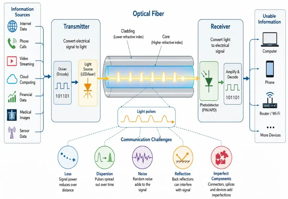
Optical fiber communication is the use of light travelling through optical fibers to transmit information. Instead of sending electrical signals through metal wires, a fiber optic communication system sends pulses or modulated waves of light through a thin strand of glass or plastic. These light signals may carry internet data, telephone conversations, video streams, medical images, financial transactions, cloud-computing traffic, sensor data, and many other forms of digital information.
The basic idea is elegant. Information is first converted into an optical signal by a transmitter. The signal travels through an optical fiber, guided by the same physical principles studied in Total Internal Reflection and Optical Fibers. Along the way, the signal may be affected by loss, dispersion, noise, reflection, and imperfect components. At the far end, a receiver detects the light and converts it back into an electrical signal that computers, phones, routers, or other systems can use.
This page belongs to the wider Fiber Optics cluster in Light and Optics. It connects the physics of light guidance, fiber modes and dispersion, optical amplifiers and signal loss, and practical communication networks into one coherent system.
Optical fiber communication converts electrical information into light, sends it through an optical fiber, and converts it back into usable data at the receiver.
Learning Pathway Within the Fiber Optics Module
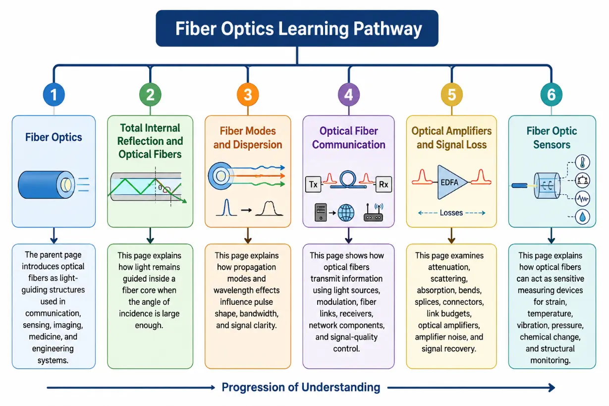
Optical fiber communication is easier to understand when it is placed in the correct learning sequence. Students should first see how light is guided inside a fiber, then how signals change as they travel, then how information is encoded, transmitted, amplified, received, and interpreted. Use the roadmap below to navigate across the cluster levels:
Study how different guided modes, wavelengths, and propagation effects influence pulse spreading, bandwidth, and signal clarity.
Optical Fiber Communication
Current module. This page shows how optical fibers transmit information using light sources, modulation, fiber links, receivers, network components, and signal-quality control.
This page explains how optical fibers can act as sensitive measuring devices for strain, temperature, vibration, pressure, chemical change, and structural monitoring.
This learning pathway places Optical Fiber Communication within the wider Fiber Optics cluster, showing how students move from light guidance to signal behaviour, communication systems, amplification, loss management, and sensing.
What Optical Fiber Communication REALLY Means
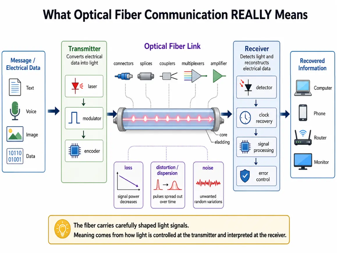
Optical fiber communication is not simply “light travelling through a cable.” It is a complete information system. A message must be converted into an optical form, carried through a physical medium, protected against loss and distortion, detected at the far end, and reconstructed with enough accuracy to be useful.
In a simple view, a transmitter turns electrical data into light. The optical fiber guides that light over distance. A receiver turns the arriving light back into electrical data. In a more realistic view, the system also includes lasers, modulators, connectors, splices, couplers, multiplexers, amplifiers, detectors, clocks, error control, signal processing, and network equipment.
The deeper idea is that optical fiber communication works because light can carry information at very high speed and over long distances with low loss. The fiber does not understand the message. It only carries carefully shaped optical signals. The meaning comes from how the light is controlled at the transmitter and interpreted at the receiver.
Optical fiber communication is more than light travelling through a cable; it is a full system that converts information into light, carries it through a fiber link, and reconstructs it at the receiver.
Theoretical Framework: Shannon Channel Capacity, Chromatic Limits, and Power Link Allocations
To analyze data throughput and link reaches with comprehensive undergraduate physical rigor, students must evaluate the mathematical bounds governing information density and link power structures.
The Shannon-Hartley Capacity Theorem in Optical Channels
The ultimate limits of data capacity across any communication link—including a single-mode optical fiber channel—are dictated by the Shannon-Hartley theorem. This relationship binds the maximum error-free data rate C (in bits per second) to the available physical channel bandwidth B and the received optical signal-to-noise ratio (SNR):
$$C = B \log_2\left(1 + \text{SNR}\right)$$
Because the carrier frequencies of light operating within the near-infrared telecommunication windows are exceptionally high (spanning roughly 193 THz in the 1550 nm band), the absolute raw bandwidth B available in optical fiber infrastructure dwarfs traditional copper lines. To maximize this capacity parameter under severe SNR limits, modern optical transmitters abandon basic on-off keying and implement high-order coherent modulation schemes. These advanced configurations manipulate both the amplitude and the phase of the carrier wavefront to pack multiple bits into every individual symbol interval.
The Bit-Rate and Distance Distortion Trade-Off
While the Shannon theorem maps out the capacity threshold based on background noise, the maximum distance a high-speed signal can travel before becoming unreadable is limited by chromatic dispersion. When a light pulse of spectral width Δλ travels through a fiber segment of length L, its temporal pulse broadening Δτ can be expressed as:
$$\Delta\tau = D \cdot \Delta\lambda \cdot L$$
Where D is the system’s chromatic dispersion parameter, measured in units of ps/(nm·km). To guarantee that adjacent pulses do not spread into one another and trigger inter-symbol interference, the total expanded pulse width must remain well within the absolute time slot assigned to a single bit. This requirement sets a fundamental system design bottleneck where the maximum bit-rate Rbit scales inversely with transmission length:
$$R_{\text{bit}} \cdot \Delta\tau \le 1 \Rightarrow R_{\text{bit}} \cdot D \cdot \Delta\lambda \cdot L \le 1$$
Basic Structure of an Optical Fiber Communication System
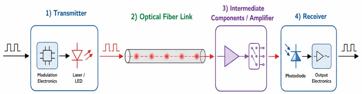
A typical optical fiber communication system has four main parts: a transmitter, an optical fiber link, intermediate components or amplifiers, and a receiver. Each part must work well for the whole communication link to succeed.
Transmitter: The transmitter converts electrical information into an optical signal. It uses a laser diode or light-emitting diode, together with circuits that control how the light is switched, modulated, or shaped.
Optical Fiber Link: The optical fiber link carries the light from transmitter to receiver. It includes long fiber spans, patch cords, connectors, splices, splitters, couplers, filters, and other passive optical components.
Intermediate Components: Longer or more complex systems include optical amplifiers, repeaters, wavelength multiplexers, dispersion-compensation elements, switches, and monitoring devices. These components help the signal remain usable as it travels through the network.
Receiver: The receiver detects the arriving optical signal and converts it back into an electrical signal. It houses a photodiode, amplifier, decision circuit, clock recovery system, and digital signal-processing electronics.
An optical fiber communication system converts electrical information into light, sends it through an optical fiber link, supports the signal with intermediate components when needed, and converts it back into an electrical signal at the receiver.
This simple diagram shows the basic structure of an optical fiber communication system. The signal begins at the transmitter, where modulation electronics drive a laser or LED to convert electrical information into light. The light then travels through the optical fiber link as a guided optical signal. In longer or more complex systems, intermediate components such as amplifiers, switches, multiplexers, or other signal-support devices may help keep the signal usable. At the receiver, a photodiode detects the incoming light and output electronics convert it back into an electrical signal for further processing.
Modulation Modalities and Signal Carrier Frameworks
Before information can travel through an optical fiber, it must undergo modulation—a process where properties of the high-frequency light carrier wave are altered to echo a digital bit stream. Engineers categorize these methods based on the specific light properties changed by the system:
Intensity Modulation (IM): The simplest configuration. It varies the optical power output directly, mapping logical ones and zeros to high and low brightness states. It is widely paired with direct detection schemes because of its hardware simplicity.
Phase Modulation (PM): Alters the relative phase profile of the optical carrier wave rather than its amplitude. This approach is central to modern coherent networks, allowing more bits to be encoded into every symbol interval.
Wavelength-Division Multiplexing (WDM): Combines multiple independent optical carrier frequencies into a single physical waveguide. Each unique wavelength channel carries its own isolated data signal without mixing, allowing existing fiber optic paths to scale their total data capacity dramatically.
Optical Receivers and Noise Analysis
At the far end of the transmission span, the incoming light is captured by specialized semiconductor receiver components designed to convert optical variations back into electrical waveforms:
PIN Photodiodes: Integrate an intrinsic semiconductor layer sandwiched between heavily doped p-type and n-type regions. They offer fast response times and excellent linearity, making them reliable for standard short-reach and medium-haul receiver modules.
Avalanche Photodiodes (APD): Utilize high reverse-bias voltages to induce internal electron multiplication. This creates an avalanche gain effect that increases overall sensitivity, allowing APDs to read weaker signals over longer distances.
Bit Error Rate (BER) and Eye Diagrams: Performance parameters are monitored using a bit error rate metric, which tracks the percentage of bits misread by the receiver decision loop. Technicians evaluate this performance using an eye diagram; a wide-open eye pattern indicates clear separation between signal states, while a closing eye shape warns of noise, timing errors, or severe inter-symbol interference.
Applications of Optical Fiber Networks
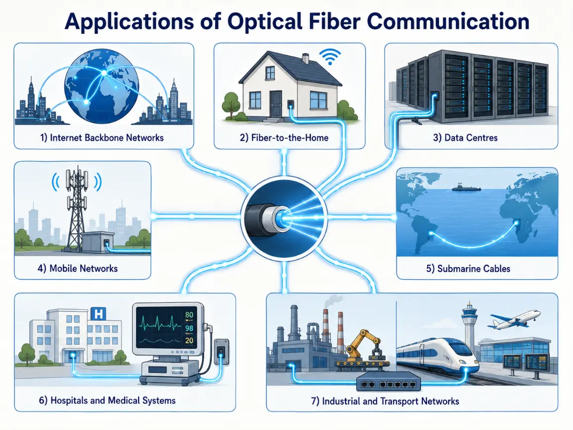
Optical fiber communication networks form the global backbone of modern digital life, deployed across various infrastructure domains:
Internet Core Backbones
Transcontinental networks and data lines deploy dense wavelength multiplexing systems to route global network traffic between major routing exchanges.
Fiber-to-the-Home (FTTH)
Passive optical networks use glass waveguides to connect residential neighborhoods directly to high-speed broadband infrastructures.
Data Centre Networks
Hyperscale facilities deploy single-mode and laser-optimized multimode links to connect processing arrays and server grids with low latencies.
Submarine Cable Systems
Heavy, armored undersea cables span oceans to bridge international data backbones and link remote continents together securely.
Optical fiber lines carry digital traffic across home access systems, hospital grids, automation plants, and deep transoceanic channels.
This illustration shows the main applications of optical fiber communication. It presents fiber links supporting internet backbone networks between cities and continents, fiber-to-the-home broadband for homes and businesses, high-speed data centre connections, mobile network backhaul and fronthaul, submarine cables carrying global traffic across oceans, hospital and medical data systems, and industrial and transport networks. The central optical fiber symbol connects these application areas, showing how guided light signals form the hidden communication infrastructure behind modern digital services.
Common Conceptual Misunderstandings
The Light Velocity Fallacy
Misconception: Internet latency is fast solely because light inside glass travels at the absolute speed of light in a vacuum. Reality: Light moves more slowly inside silica glass because of the material’s refractive index, dropping velocity by about 30%. Total internet speed is determined by available channel bandwidths, equipment processing queues, and routing protocols.
The Core Waveguide Isolation Illusion
Misconception: Because light remains trapped by total internal reflection, signals inside a fiber are completely immune to physical distortions. Reality: Trapped signals are still vulnerable to optical impairments. Pulse power levels decay continuously through attenuation, and spectral waves spread over distance via chromatic dispersion, requiring amplifiers and electronic signal management.
Interactive Quick Checks
Quick Check: Communication Backbones
1. In optical fiber communication, what carries the information through the fiber?
Information is carried by light signals. The information may be encoded through changes in intensity, phase, wavelength, polarization, or other optical properties.
2. What is the role of the transmitter in an optical fiber communication system?
The transmitter converts electrical data into an optical signal that can travel through the fiber waveguide.
3. Why can dispersion cause errors even if some light still reaches the receiver?
Dispersion can spread pulses so that neighbouring symbols overlap. The receiver may then have difficulty deciding which bit or symbol was sent, creating data errors.
Numerical Practice: Link Budget and Capacity Math
Numerical Problems and Solutions
Problem 1: A point-to-point fiber communication link spans 60 km and has an attenuation constant of 0.20 dB/km. Calculate the total fiber loss.
Multiply the linear attenuation coefficient by the link distance parameter:
Answer: The total fiber attenuation loss is exactly 12 dB.
Problem 2: A transmitter module launches 4 dBm into a single-mode fiber line. If the link budget calculates a total combined loss of 21 dB across spans and connectors, determine the received power level.
Subtract the total channel path loss directly from the transmitter launch power:
Problem 3: An optical receiver sensitivity threshold requires at least −24 dBm to ensure low bit error rates. If a link delivers an actual power of −18 dBm, find the available link power margin.
Subtract the minimum required sensitivity floor from the actual received power:
Answer: The available system power margin is exactly 6 dB.
Problem 4: A dense wavelength division multiplexing (DWDM) terminal system runs 32 distinct light channels inside a single fiber core. If each discrete wavelength channel carries a data rate of 100 Gb/s, calculate the total fiber capacity.
Multiply the individual channel data rate by the total number of channels:
Answer: The combined capacity of the system is exactly 3.2 Tb/s.
Problem 5: A core signal runs along 25 km of fiber with an attenuation rate of 0.3 dB/km. The channel includes four patch connectors with a loss of 0.4 dB each, and five fusion splices with a loss of 0.1 dB each. Calculate the total link path loss.
Calculate and sum each individual loss parameter across the path:
Answer: The total link path loss measures exactly 9.6 dB.
Problem 6: An optical transceiver system transmits a digital data stream at a modulation speed of 25 Gb/s. Estimate the available time window assigned to a single bit.
The available bit duration is the reciprocal of the total data rate parameter:
Convert seconds into picoseconds ($4.0 \times 10^{-11} \times 10^{12}$):
$$T_{\text{bit}} = 40\text{ ps}$$
Answer: Each discrete bit occupies a time duration of exactly 40 ps.
Problem 7: An optical channel suffers a passive loss of 16 dB before passing through an inline EDFA module that provides 12 dB of gain. Determine the net loss after amplification.
Subtract the positive amplifier gain value directly from the passive loss level:
Answer: The net system loss after active amplification is exactly 4 dB.
Problem 8: A legacy fiber infrastructure carries 8 wavelength channels, each running at a rate of 10 Gb/s. The system is upgraded to carry 40 unique channels, each running at a rate of 100 Gb/s. Determine the multiplier factor by which the capacity increased.
First, calculate the total data capacity of the original legacy link configuration:
Answer: The total communication capacity increases by a factor of exactly 50.
Key Terms
Transmitter
An optoelectronic module that modulates a laser or light-emitting diode source to convert electrical data waveforms into optical signals.
Receiver
An optoelectronic assembly containing a photodiode that catches incoming light and converts photon variations back into electrical signals.
Modulation
The process of altering physical properties of an optical carrier wave (such as intensity, phase, or wavelength) to encode data streams.
Wavelength-Division Multiplexing (WDM)
A network technology that routes multiple independent data signals through a single fiber path simultaneously by assigning each a distinct wavelength.
Bit Error Rate (BER)
The fractional ratio tracking the number of digital bits received with errors relative to the total number of bits transmitted.
Receiver Sensitivity
The minimum threshold of received optical power required by a photodiode circuit to decode data reliably without exceeding target error rates.
External References
The Fiber Optic Association — Operational landing platforms covering structural cable deployments, connector splicing practices, and power testing loss kits.
RP Photonics Encyclopedia — Comprehensive physics summaries tracking laser diode modulations, photodiode noise baselines, and waveguide mode parameters.
Optica Publishing Group — Scientific publication archives cataloging developments across high-order coherent transceivers and planar optical switching matrices.
IEEE Xplore Digital Library — Engineering literature indexing advancements across passive optical access networks and digital signal processing chips.
International Telecommunication Union — Global telecommunication infrastructure frameworks detailing physical layer channel grids and standardized bit-rate tolerances.
Summary
Optical fiber communication uses light guided through optical fibers to transmit information. A transmitter converts electrical data into an optical signal, the fiber carries the signal, and a receiver detects the arriving light and reconstructs the information. The performance of a fiber communication system depends on much more than whether light can enter the fiber. Engineers must consider modulation, attenuation, dispersion, noise, receiver sensitivity, link budgets, amplifiers, connectors, splices, wavelength channels, and network architecture. Optical fiber communication is one of the foundations of modern digital society. It supports internet backbones, submarine cables, data centres, mobile networks, fiber-to-the-home systems, hospitals, transport systems, and industrial networks. Its success comes from the combination of optical physics, electronic engineering, photonic devices, careful installation, and intelligent network design.
Reflection Question
If optical fibers carry most of the world’s digital information as invisible pulses of light, how should future students think differently about the connection between physics, communication, infrastructure, and everyday online life?