Prepare for University Studies & Career Advancement
Total Internal Reflection and Optical Fibers
Total internal reflection is the optical principle that allows light to remain trapped inside an optical fiber. Instead of escaping through the side of the fiber, light repeatedly reflects from the boundary between the fiber core and cladding, allowing signals to travel over long distances through a thin strand of transparent material.
This idea connects geometrical optics with modern communication technology. At the ray level, total internal reflection can be understood using refraction, critical angle, and Snell’s law. At the technology level, it explains why optical fibers can carry internet data, medical images, laser signals, and sensor information through flexible glass or plastic guides.
Optical fibers are not simply transparent wires. They are carefully engineered waveguides. A typical fiber has a central core with a slightly higher refractive index, surrounded by cladding with a slightly lower refractive index. This small difference in refractive index is enough to guide light along the fiber when the light enters within the correct range of angles.
This page begins the Fiber Optics cluster under Light and Optics. It provides the physical foundation for later pages on fiber modes and dispersion, optical fiber communication, optical amplifiers and signal loss, and fiber optic sensors.
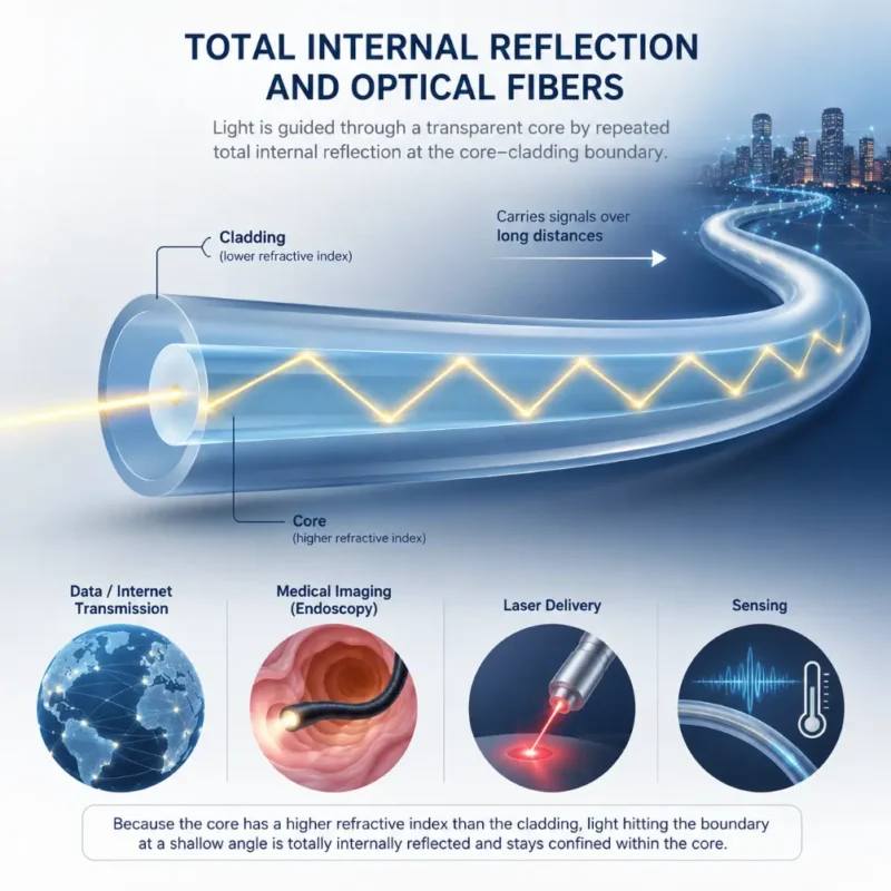
Optical fibers guide light by total internal reflection, keeping signals confined inside the higher-index core as they travel through the fiber.
This artist’s impression introduces total internal reflection in optical fibers. It shows light entering a transparent fiber core and reflecting repeatedly at the boundary between the higher-index core and the lower-index cladding. The guided light path illustrates how optical fibers can carry signals over long distances without escaping through the sides. The supporting icons connect the same principle to data and internet transmission, medical endoscopy, laser delivery, and fiber optic sensing.
Learning Pathway Within the Fiber Optics Module
Total internal reflection is the first major idea students should understand before studying optical fibers in greater depth. Once students know how light can be guided inside a fiber, they can then explore how different modes travel, how pulses spread, how data is transmitted, why signals weaken, and how fibers can act as sensors. Use the roadmap below to navigate across the cluster levels:
Total Internal Reflection and Optical Fibers
Current module. Explains the critical angle, guiding condition, fiber core, cladding, numerical aperture, and the basic reason light can remain trapped inside a fiber.
Shows how changes in light inside fibers can measure strain, temperature, pressure, vibration, and environmental conditions.
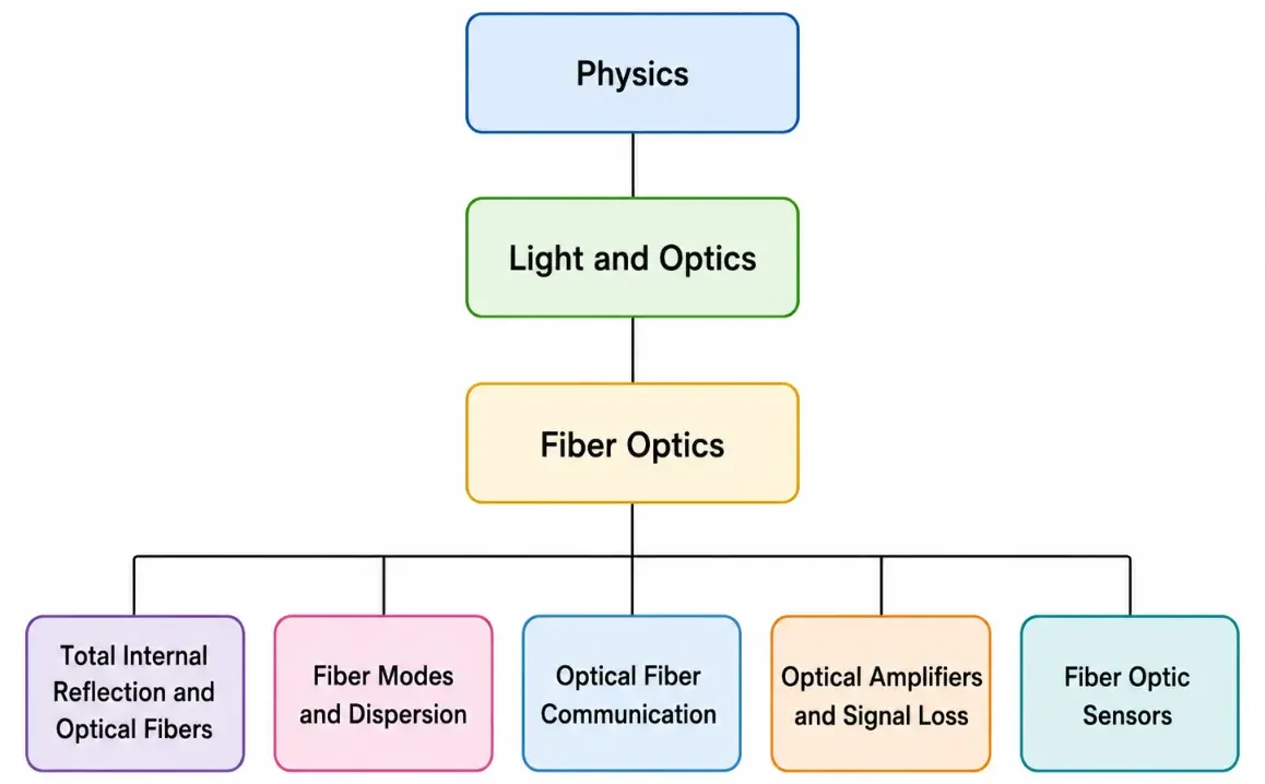
This tree chart shows how the Fiber Optics cluster branches from Physics and Light and Optics into five connected subpages on light guiding, modes, communication, signal loss, and sensing.
This simple tree chart presents the learning pathway for the Fiber Optics cluster on Prep4Uni.online. It begins with Physics, narrows to Light and Optics, then to Fiber Optics, before branching into five related subpages: Total Internal Reflection and Optical Fibers, Fiber Modes and Dispersion, Optical Fiber Communication, Optical Amplifiers and Signal Loss, and Fiber Optic Sensors. The structure helps students see how total internal reflection provides the foundation before they study light modes, pulse spreading, data transmission, signal weakening, amplification, and fiber-based sensing.
What Total Internal Reflection REALLY Means
Total internal reflection means that light trying to pass from a higher-refractive-index medium into a lower-refractive-index medium can be completely reflected back into the first medium, provided the angle of incidence is large enough. The word “total” is important: under ideal conditions, all the light is reflected rather than partly transmitted.
This does not happen for every boundary or every angle. If light travels from air into glass, it bends toward the normal and does not undergo total internal reflection. Total internal reflection requires light to travel from an optically denser medium to an optically less dense medium, such as from glass to air, water to air, or a fiber core to its lower-index cladding.
In an optical fiber, total internal reflection is used in a controlled way. Light is launched into the fiber core. When it reaches the core-cladding boundary at a suitable angle, it reflects back into the core. After many such reflections, the light can continue along the fiber instead of leaking away through the sides.
The key idea is simple but powerful: a fiber guides light not by using mirrors along its length, but by using a refractive-index boundary built into the material itself.
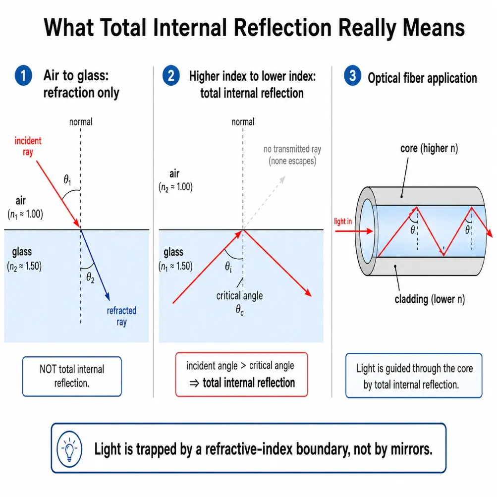
This diagram shows that total internal reflection occurs only when light travels from a higher-index medium to a lower-index medium at an angle greater than the critical angle, and it explains how this principle guides light in an optical fiber.
This educational diagram explains what total internal reflection really means through three linked panels. The first panel shows light travelling from air into glass, where it refracts rather than undergoing total internal reflection. The second panel shows light travelling from glass toward air at an angle greater than the critical angle, so the light is completely reflected back into the glass. The third panel applies the same idea to an optical fiber, where light is guided through the higher-index core by repeated reflection at the boundary with the lower-index cladding. Together, the panels help students see that light in a fiber is trapped by a refractive-index boundary rather than by mirrors.
Refraction and Snell’s Law
When light crosses from one transparent medium into another, its speed changes. This change in speed usually causes the light ray to bend. The relationship between the incident and refracted angles is described by Snell’s law:
$$n_1 \sin \theta_1 = n_2 \sin \theta_2$$
Here, n1 and n2 are the refractive indices of the two media. θ1 is the angle of incidence, and θ2 is the angle of refraction. Both angles are measured from the normal, not from the surface.
A higher refractive index means light travels more slowly in that medium. Glass usually has a higher refractive index than air, so light slows down when entering glass from air. In optical fibers, the core has a slightly higher refractive index than the cladding, which is what makes light guidance possible.
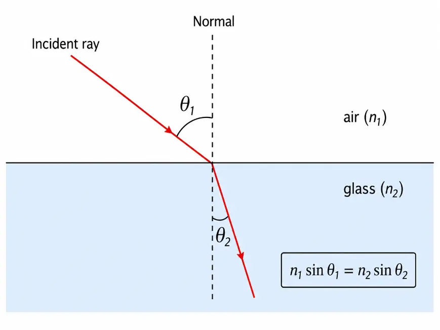
Snell’s law describes how light bends when it crosses from one transparent medium into another, with both angles measured from the normal.
This simple educational diagram illustrates refraction and Snell’s law. A light ray travels from air into glass and bends toward the normal because glass has a higher refractive index and light travels more slowly in it. The incident angle θ₁ and refracted angle θ₂ are both measured from the normal, not from the surface. The equation n₁ sin θ₁ = n₂ sin θ₂ summarises the relationship between refractive index and bending at the boundary.
Critical Angle Principles
The critical angle is the angle of incidence in the higher-index medium for which the refracted ray just skims along the boundary. At this angle, the angle of refraction is exactly 90°.
For light travelling from medium 1 into medium 2, where n1 > n2, the critical angle θc is found from:
$$\sin \theta_c = \frac{n_2}{n_1}$$
If the angle of incidence is smaller than the critical angle, some light refracts out of the higher-index medium. If the angle of incidence is equal to the critical angle, the refracted ray travels along the boundary. If the angle of incidence is greater than the critical angle, total internal reflection occurs.
Two conditions must be satisfied for total internal reflection to occur:
Light must travel from a higher-refractive-index medium to a lower-refractive-index medium.
The angle of incidence inside the higher-index medium must be greater than the critical angle.
Both conditions matter. A ray inside glass can undergo total internal reflection at a glass-air boundary, but a ray travelling from air into glass cannot. Similarly, even inside glass, total internal reflection will not occur unless the ray strikes the boundary at an angle greater than the critical angle.
Structure of an Optical Fiber
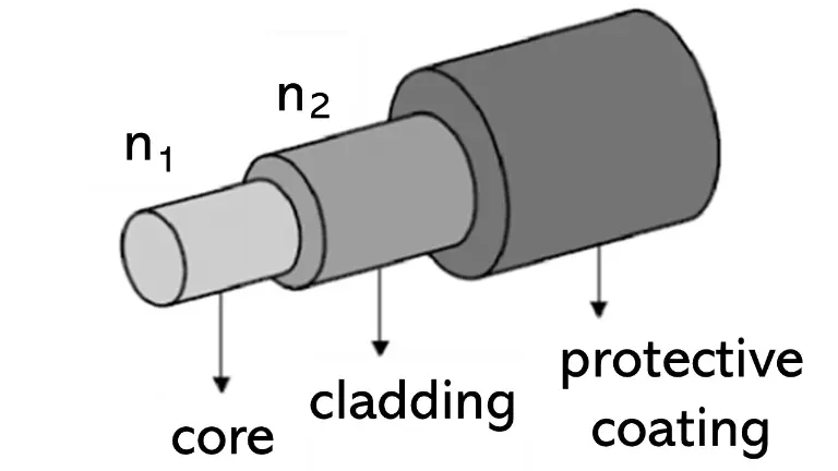
A basic optical fiber has three important parts: the core, the cladding, and the protective coating. Each part has a different role.
Core: The central region through which most of the guided light travels. It is made from highly transparent glass or plastic. The refractive index of the core is slightly higher than that of the surrounding cladding.
Cladding: Surrounds the core. Its refractive index is slightly lower than the core’s refractive index. This difference allows total internal reflection to occur at the core-cladding boundary.
Protective Coating: The protective coating or buffer surrounds the cladding. It does not guide the light directly. Its purpose is to protect the fiber from scratches, moisture, bending stress, and mechanical damage.
An optical fiber has a central core, a surrounding cladding layer, and an outer protective coating; the core has a higher refractive index than the cladding so light can be guided.
This simple diagram shows the basic layered structure of an optical fiber. The core is the central light-guiding region and has a higher refractive index, labelled n₁. The cladding surrounds the core and has a slightly lower refractive index, labelled n₂, allowing total internal reflection at the core-cladding boundary. The outer protective coating surrounds the cladding and protects the fiber from physical damage, moisture, and bending stress. This structure helps students understand why optical fibers can guide light efficiently through a thin transparent strand.
Light Trapping: Numerical Aperture and The Acceptance Cone
Light entering an optical fiber must enter within a suitable range of angles. If it enters too steeply, it will strike the core-cladding boundary at an angle less than the critical angle and escape into the cladding. The acceptance cone is the cone of angles within which incoming light can enter the fiber and still be guided by total internal reflection.
The size of this acceptance cone is quantified by the numerical aperture (NA), which measures the light-gathering ability of the fiber. For a fiber in air, the numerical aperture is written as:
Where θmax represents the maximum half-angle of the acceptance cone. A larger numerical aperture means the fiber can accept light over a wider range of angles. However, a larger core and higher NA allow more modes inside multimode fibers, which increases pulse distortions.
Step-Index and Graded-Index Refractive Profiles
Step-Index Fiber: The refractive index changes abruptly at the core-cladding boundary. The core has one steady refractive index, and the cladding has a lower index, making the boundary sharp. Rays reflect cleanly at the boundary, meaning steeper paths travel longer distances than straight lines down the middle.
Graded-Index Fiber: The refractive index gradually decreases from the center of the core outward toward the cladding. Instead of bouncing sharply off boundaries in a zigzag path, light rays curve smoothly through the core. Because light travels faster in the lower-index outer regions, the longer curved paths are speed-compensated, allowing different light paths to arrive closer together in time.
Applications of Core Light Guiding
Confining light using index boundaries supports technologies across digital, manufacturing, and clinical industries:
Telecommunication Networks
Optical fibers carry internet data, phone signals, video streams, and cloud traffic through long-distance and local networks.
Medical Endoscopy
Bundles of optical fibers carry light into the body and transmit images back to a camera, supporting minimally invasive examinations.
High-Power Laser Delivery
Fibers deliver heavy laser beams to precise spots for high-precision manufacturing, cutting, and laser medical surgeries.
Industrial Cavity Inspection
Flexible fiber lines direct illumination inside narrow machine spaces, engines, and plumbing tubes where direct sight is blocked.
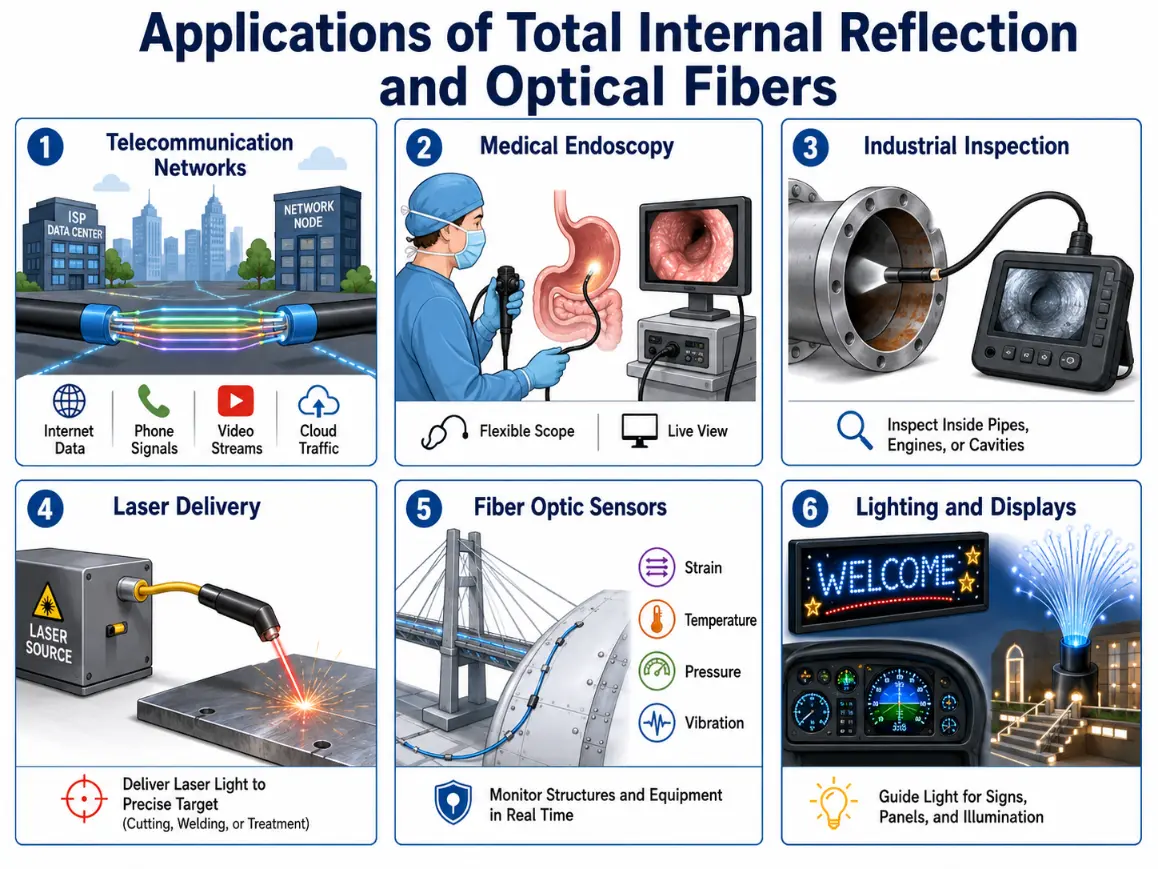
Optical fibers use total internal reflection to guide light for communication, medical imaging, inspection, laser delivery, sensing, and illumination.
This infographic shows major applications of total internal reflection and optical fibers. It illustrates how optical fibers carry internet data, phone signals, video streams, and cloud traffic through telecommunication networks. It also shows medical endoscopy, where flexible fiber-based instruments bring light and imaging into the body; industrial inspection, where fibers help view the inside of pipes, engines, and cavities; and laser delivery, where guided light reaches precise targets for cutting, welding, treatment, or experiments. The image also highlights fiber optic sensors for monitoring strain, temperature, pressure, and vibration, as well as lighting and display uses where fibers guide light safely and flexibly.
Common Conceptual Misunderstandings
The Hollow Pipe Misconception
Misconception: Optical fiber cables are hollow glass tubes that act like reflective pipes with light mirroring down the empty center. Reality: Most telecommunication fibers are solid silica glass rods. Light remains trapped inside the central core region because of continuous material refractive index constraints, not mirror coatings.
The Absolute Reflection Illusion
Misconception: Total internal reflection ensures that zero light power is ever lost along the link, allowing infinite travel lengths. Reality: While internal reflection is highly efficient at boundaries, photons are still lost over distance due to glass absorption dynamics, Rayleigh scattering, and micro-bending stress leaks.
Interactive Quick Checks
Quick Check: Critical Angle and Boundary Operations
1. What two conditions are required for total internal reflection?
Light must travel from a higher-refractive-index medium to a lower-refractive-index medium, and the angle of incidence must be greater than the critical angle.
2. Why can light travelling from air into glass not undergo total internal reflection at that boundary?
Total internal reflection requires light to travel from a higher-index medium to a lower-index medium. Air has a lower refractive index than glass, so light travelling from air into glass does not satisfy this condition.
3. If the critical angle is 42° and the incident angle is 35°, will total internal reflection occur?
No. The incident angle must be greater than the critical angle. Since 35° is less than 42°, some light refracts out instead of being totally internally reflected.
Quick Check: Fiber Specifications
1. Why must the core of an optical fiber have a higher refractive index than the cladding?
The core must have a higher refractive index so that light inside the core can meet a lower-index boundary at the cladding. This allows total internal reflection to guide the light.
2. What does the acceptance cone describe?
The acceptance cone describes the range of input angles within which light can enter the fiber and still be guided by total internal reflection.
3. Why can sharp bending cause light loss in a fiber?
Sharp bending changes the effective angle at which light meets the core-cladding boundary, causing rays to strike at angles less than the critical angle and leak into the cladding.
Worked Example 1: Light travels from glass with a refractive index of 1.50 toward an air boundary with a refractive index of 1.00. Calculate the critical angle.
Answer: The critical angle is approximately 41.8°.
Worked Example 3: An optical fiber features a core refractive index of 1.48 and a cladding refractive index of 1.46. Estimate its numerical aperture for a fiber operating in air.
Answer: The maximum acceptance angle is approximately 12.7°.
Problem 1: Light travels from a water layer with a refractive index of 1.33 toward an air boundary with a refractive index of 1.00. Find the critical angle.
Answer: The maximum acceptance angle is approximately 10.4°.
Problem 5: A customized fiber core features an index of 1.50 and a cladding index of 1.49. Calculate the critical angle right at the core-cladding boundary boundary.
Divide the cladding index by the core index to locate the sine value:
Answer: The boundary critical angle is approximately 83.4°.
Key Terms
Total internal reflection
The optical phenomenon where light attempting to cross into a lower-index medium is entirely reflected back into the denser medium at angles past the critical threshold.
Critical angle
The precise angle of incidence for which the corresponding angle of refraction stretches out to exactly 90°.
Core
The high-purity central transparent pathway of an optical fiber that retains a higher refractive index to trap signals.
Cladding
The outer layer wrapped around a fiber core that features a lower refractive index to enforce reflection boundaries.
Acceptance cone
The clear spatial range of input angles within which incoming light can enter the core structure and remain guided.
Numerical aperture (NA)
A dimensionless parameter mapping the total light-gathering capacity and angular acceptance cone of an optical waveguide.
Total internal reflection occurs when light travels from a higher-refractive-index medium toward a lower-refractive-index medium and strikes the boundary at an angle greater than the critical angle. Under these conditions, the light is reflected back into the higher-index medium. Optical fibers use this principle by placing a higher-index core inside a lower-index cladding. Light launched into the fiber within the acceptance cone can remain guided along the core through repeated internal reflection or, in a fuller wave description, through guided modes. The core, cladding, numerical aperture, acceptance cone, bending behaviour, and material quality all affect how well a fiber guides light. Real fibers can lose light through absorption, scattering, bending, connector loss, and imperfect coupling. Total internal reflection provides the foundation for fiber optics, but later topics add more detail: modes and dispersion explain pulse spreading, communication systems explain data transmission, amplifiers and losses explain long-distance signal management, and fiber sensors show how light can measure physical changes.
Reflection Question
If light normally spreads out from a source, what does optical fiber design teach us about how carefully chosen boundaries can turn spreading light into a guided signal?