
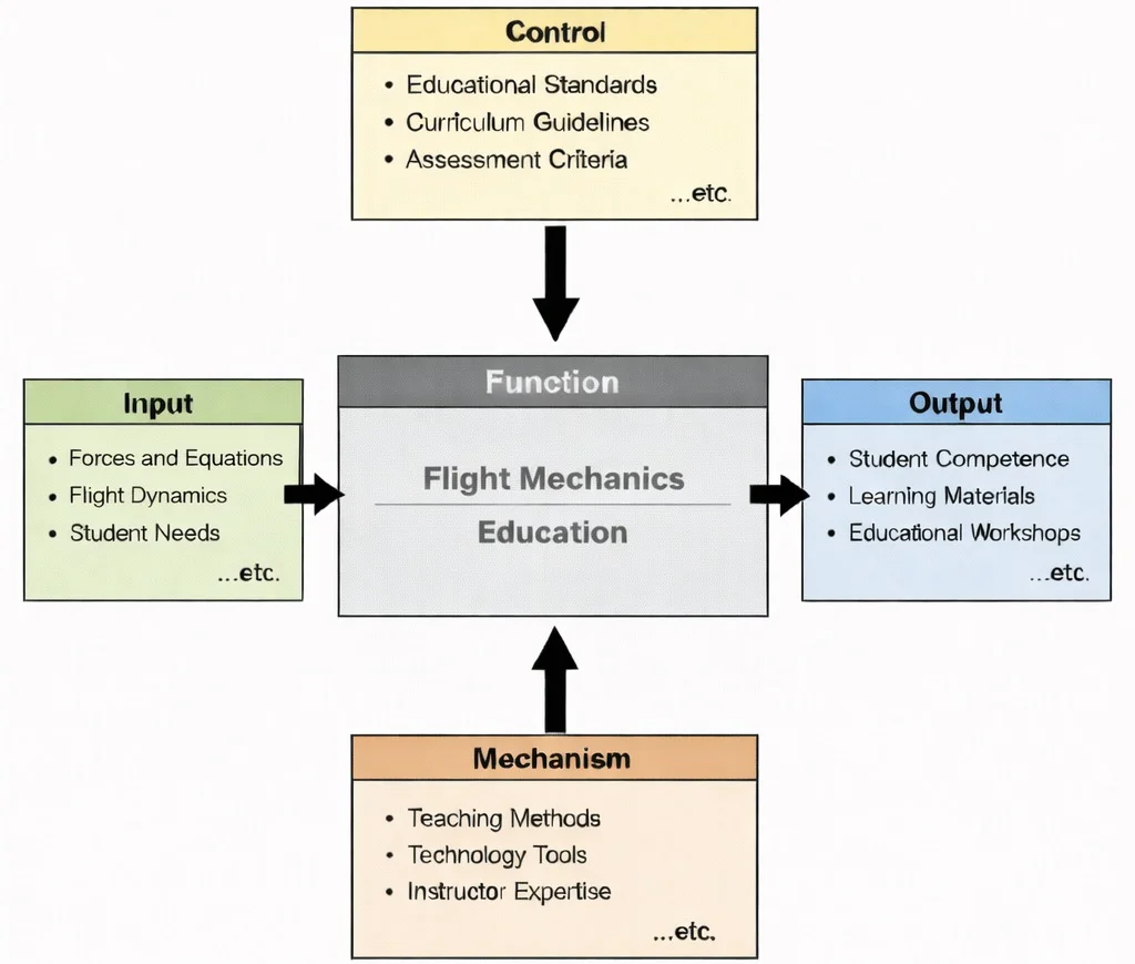
IDEF0 functional decomposition of Flight Mechanics Education: classical Newtonian force balances and aero dynamic inputs structured by airworthiness curriculum standards, realized through computational 6-DOF simulation mechanisms, and generating certified trajectory analysis and trim design competencies.

Flight Mechanics: formalizing the mathematical balance between aerodynamic vectors, propulsion thrust lines, and gravitational moments that determine vehicle 6-DOF dynamic equilibrium and flight trajectories.
The image depicts a propeller aircraft surrounded by technical diagrams—circular plots, vector arrows, and annotated notes—suggesting the analytical “language” of flight mechanics. Visual cues point to the four main forces (lift, weight, thrust, drag) and to stability and control ideas such as pitch, roll, yaw, and control surfaces. The overall composition conveys how flight mechanics links aerodynamic forces and moments to aircraft motion, helping engineers predict performance, ensure stability, and design safe, controllable flight trajectories.
Motion, Stability, and Trajectory Dynamics
Aerospace & Aeronautical – Overview
Brings together forces, motion, and system behaviour across atmospheric and space flight regimes to establish macro-level vehicle design envelopes.
Flight Mechanics (Current Module)
Analyses how vector forces and aerodynamic moments govern translational 6-DOF motion, static/dynamic stability, and trajectory evolution.
Celestial Mechanics
Extends motion analysis into vacuum orbital regimes where central gravitational forces dominate system trajectories and orbital maneuvers.
Aerodynamics
Supplies external lift, drag, and pressure force distributions that directly drive motion equations within atmospheric layers.
Propulsion Systems
Provides propulsive thrust inputs that alter vehicle linear acceleration, climb rates, and overall flight envelope performance.
Aero Control Systems & Robotics
Regulates vehicle motion through closed-loop feedback algorithms that actuate control surfaces to stabilize flight dynamics.
Avionics
Supplies real-time pitot-static and inertial navigation data required by pilots and autopilots to execute controlled trajectories.
Aerospace Structures
Establishes load-bearing limits that constrain allowable maneuvering accelerations and high-g flight envelopes.
Aero Materials Science
Determines structural fatigue endurance under cyclic g-loads and turbulence encounters across long service lives.
Hypersonics
Introduces highly non-linear flight mechanics coupling extreme aerothermal heating with shock-wave interactions at Mach 5+.
Spacecraft Engineering
Applies motion principles to atmospheric entry, descent, landing (EDL), and orbital transfer burn execution.
Satellite Technology
Utilizes orbital mechanics models for precise attitude determination, station-keeping, and constellation slot alignment.
Core Areas of Flight Mechanics
1. Motion Analysis
A jet transport aircraft with unaccelerated 1g level stall speed \(V_{\text{s0}} = 62.0 \text{ m/s}\) (120.5 knots) executes a sustained, altitude-conserving level coordinated turn at a bank angle \(\phi = 60.0^\circ\). Calculate the resultant load factor \(n\), the dynamic lift force \(L\) required for an aircraft of mass \(m = 75,000 \text{ kg}\) (\(g = 9.81 \text{ m/s}^2\)), the accelerated turn stall speed \(V_{\text{s,turn}}\), and the turn radius \(R\) at a true airspeed \(V_\infty = 180.0 \text{ m/s}\).
Sequential Derivation & Calculation:
Step 1: Calculate the maneuvering load factor \(n\):
$$n = \frac{1}{\cos(\phi)} = \frac{1}{\cos(60.0^\circ)} = \frac{1}{0.50} = \mathbf{2.00 \text{ g}}$$Step 2: Calculate level flight weight and total maneuvering lift force \(L\):
$$W = m \cdot g = 75,000 \text{ kg} \times 9.81 \text{ m/s}^2 = 735,750 \text{ N} \quad (735.75 \text{ kN})$$ $$L = n \cdot W = 2.00 \times 735,750 \text{ N} = \mathbf{1,471,500 \text{ N}} \quad (\mathbf{1,471.50 \text{ kN}})$$Step 3: Calculate the accelerated stall speed \(V_{\text{s,turn}}\):
$$V_{\text{s,turn}} = V_{\text{s0}} \sqrt{n} = 62.0 \text{ m/s} \times \sqrt{2.00} = 62.0 \times 1.4142 = \mathbf{87.68 \text{ m/s}} \quad (\mathbf{170.4 \text{ knots}})$$Step 4: Compute the turn radius \(R\) in the horizontal plane:
$$R = \frac{V_\infty^2}{g \cdot \tan(\phi)} = \frac{(180.0 \text{ m/s})^2}{9.81 \text{ m/s}^2 \times \tan(60.0^\circ)} = \frac{32,400}{9.81 \times 1.73205} = \frac{32,400}{16.9914} = \mathbf{1,906.85 \text{ m}} \quad (\mathbf{1.91 \text{ km}})$$Flight Dynamics Analysis: Banking at \(60.0^\circ\) doubles total airframe load factor (\(n = 2.00g\)), which increases vehicle stall speed by \(41.4\%\) from \(62.0 \text{ m/s}\) to \(87.68 \text{ m/s}\). Pilots and automated flight control systems must maintain airspeeds well above \(V_{\text{s,turn}}\) to prevent high-speed accelerated dynamic stalls.
2. Stability in Flight
- Static Stability: The immediate initial restoring force or moment following displacement from trim. Longitudinal static stability requires that the pitching moment derivative with respect to angle of attack be strictly negative (\(C_{m\alpha} < 0\)).
- Dynamic Stability: The time-history damping of resulting oscillations. Longitudinal dynamic modes encompass the short-period mode (rapid pitch oscillation heavily damped by the horizontal stabilizer) and the phugoid mode (long-period interchange between kinetic velocity and gravitational potential altitude).
- Neutral Point & Static Margin: The vehicle aerodynamic center where pitching moment is independent of angle of attack. Static Margin (\(\text{SM}\)) determines handling qualities:
3. Control Mechanisms
- Ailerons: Modulate differential lift on outer wing panels to generate roll rate (\(p\)).
- Elevators: Modulate horizontal stabilizer downwash to generate pitch rate (\(q\)).
- Rudders: Deflect vertical fin sideforce to counter adverse yaw and control sideslip (\(\beta\)) and yaw rate (\(r\)).
- Spacecraft Actuators: Reaction wheels, Control Moment Gyroscopes (CMGs), and reaction control system (RCS) cold-gas/hydrazine thrusters providing attitude moments in microgravity vacuum regimes.
4. Flight Path Optimization
- Atmospheric Aircraft: Maximizing the Breguet cruise range parameter by flying at continuous optimal lift-to-drag ratio (\(L/D\)) and executing step climbs as aircraft mass decreases from fuel burn.
- Spacecraft Trajectories: Keplerian orbital transfers, two-impulse Hohmann transfers, bi-elliptic transfers, and planetary gravity-assist flybys minimizing total velocity change (\(\Delta V\)).
5. Fuel Efficiency
Contemporary AI-Era Computational Paradigms in Flight Mechanics
Consider an aircraft longitudinal short-period state-space approximation \(\dot{\mathbf{x}} = \mathbf{A} \mathbf{x}\) with state vector \(\mathbf{x} = [\alpha, q]^T\) (angle of attack and pitch rate):
$$\begin{bmatrix} \dot{\alpha} \\ \dot{q} \end{bmatrix} = \begin{bmatrix} Z_\alpha & 1 \\ M_\alpha & M_q \end{bmatrix} \begin{bmatrix} \alpha \\ q \end{bmatrix}$$Given dimensional stability derivatives: \(Z_\alpha = -1.25 \text{ s}^{-1}\), \(M_\alpha = -18.50 \text{ s}^{-2}\), and pitch damping derivative \(M_q = -2.10 \text{ s}^{-1}\):
Step 1: Formulate the characteristic polynomial \(\det(\lambda \mathbf{I} - \mathbf{A}) = 0\):
$$\det \begin{bmatrix} \lambda - Z_\alpha & -1 \\ -M_\alpha & \lambda - M_q \end{bmatrix} = (\lambda - Z_\alpha)(\lambda - M_q) - M_\alpha = \lambda^2 - (Z_\alpha + M_q)\lambda + (Z_\alpha M_q - M_\alpha) = 0$$Step 2: Calculate polynomial coefficients:
$$2 \zeta \omega_n = -(Z_\alpha + M_q) = -(-1.25 - 2.10) = 3.35 \text{ s}^{-1}$$ $$\omega_n^2 = (Z_\alpha M_q - M_\alpha) = [(-1.25 \times -2.10) - (-18.50)] = [2.625 + 18.50] = 21.125 \text{ s}^{-2}$$Step 3: Solve for natural undamped frequency \(\omega_n\) and damping ratio \(\zeta\):
$$\omega_n = \sqrt{21.125} = \mathbf{4.596 \text{ rad/s}}$$ $$\zeta = \frac{3.35}{2 \times 4.596} = \frac{3.35}{9.192} = \mathbf{0.364} \quad (\text{damped stable short-period mode})$$Analysis: The negative real parts of the resulting complex conjugate poles (\(\lambda_{1,2} = -\zeta\omega_n \pm j\omega_n\sqrt{1-\zeta^2} = -1.675 \pm j4.28 \text{ s}^{-1}\)) verify that the short-period pitch response rapidly damps out disturbances, satisfying civil airworthiness handling quality specifications (MIL-F-8785C Level 1 requirements).
Engineering Trade-offs in Flight Mechanics
| Flight Mechanics Trade-off | Primary Operational Benefit | Systemic Penalty / Risk | Quantitative Design Metric |
|---|---|---|---|
| Static Margin (SM) vs. Pitch Agility | Positive SM (\(5\%\text{--}12\%\)) ensures natural, pilot-friendly pitch trim stability without computer intervention. | Produces high trim drag at the horizontal tail; reduces instantaneous pitch turn rate during combat maneuvers. | Static Margin: Commercial Transports (\(+5\%\) to \(+10\%\)); Relaxed-Stability Fighters (\(-2\%\) to \(-5\%\)). |
| Wing Dihedral vs. Dutch Roll Susceptibility | Positive dihedral angle generates restoring roll moments during sideslip, ensuring lateral spiral stability. | Excessive dihedral effect (\(C_{l\beta}\)) excites lightly-damped Dutch roll yaw-roll coupled oscillations. | Dutch Roll Damping Ratio: \(\zeta_{\text{DR}} \ge 0.08\) (FAR Part 25 minimum required damping). |
| Wing Loading (\(W/S\)) Trade-off | High wing loading (\(>600 \text{ kg/m}^2\)) provides smooth ride quality in turbulence and low cruise drag. | Increases takeoff and landing field lengths; degrades sustained turn rate and climb gradient. | Wing Loading: Light Aircraft (\(50\text{--}100 \text{ kg/m}^2\)); Jet Airliners (\(500\text{--}750 \text{ kg/m}^2\)). |
| Thrust-to-Weight Ratio (\(T/W\)) vs. Fuel Fraction | High \(T/W \ge 1.0\) delivers vertical climb capability and short takeoff performance. | Requires heavy engine cores, reducing usable fuel mass fraction and lowering payload range. | Thrust-to-Weight Ratio: Commercial (\(T/W \approx 0.25\text{--}0.35\)); Supersonic Fighters (\(T/W \ge 1.0\)). |
Consider a transport aircraft with center of gravity located \(x_{\text{cg}} = 0.22 \bar{c}\) and wing-body aerodynamic center at \(x_{\text{ac}} = 0.25 \bar{c}\). The cruise weight is \(W = 1,200,000 \text{ N}\). Because the CG is \(0.03 \bar{c}\) ahead of the wing lift vector, the wing creates an intrinsic nose-down pitching moment. To maintain level trim, the horizontal tail (moment arm \(l_t = 25.0 \text{ m}\), \(\bar{c} = 5.0 \text{ m}\)) must generate a downward aerodynamic balancing force \(L_{\text{tail}}\):
$$L_{\text{tail}} = -W \frac{(x_{\text{ac}} - x_{\text{cg}})\bar{c}}{l_t} = -1,200,000 \text{ N} \times \frac{(0.25 - 0.22) \times 5.0 \text{ m}}{25.0 \text{ m}} = -1,200,000 \times \frac{0.15}{25.0} = \mathbf{-7,200 \text{ N}}$$Comparison: The main wing must generate \(L_{\text{wing}} = W + |L_{\text{tail}}| = 1,207,200 \text{ N}\) to support both aircraft weight and the tail downforce, inducing an extra \(7.2 \text{ kN}\) of lift and associated induced trim drag throughout cruise. Relaxed-stability aircraft with fly-by-wire controls position the CG near the neutral point, eliminating tail downforce and saving 2% to 4% in fleet fuel burn.
Interactive Tool: Aircraft Longitudinal Pitch Response & Static Margin Simulator
Longitudinal Pitch Dynamic Response Calculator
Interactive runtime environment: https://prep4uni.online/stem/physical-technologies/aerospace-and-aeronautical-engineering/flight-mechanics/
Applications of Flight Mechanics
1. Aircraft Design and Operation
- Flight mechanics is foundational to the design and operation of all fixed-wing and rotary aircraft, from small general aviation planes to commercial airliners and military jets.
- Engineers use principles of stability and control to ensure predictable and safe aircraft behavior during various phases of flight, including takeoff, cruising, maneuvering, and landing.
- For commercial aviation, flight mechanics optimizes fuel efficiency, reduces structural loads, and ensures compliance with safety standards like those set by the FAA and ICAO.
- In military applications, flight mechanics contributes to the development of high-performance aircraft that can execute agile maneuvers, evade radar detection, and operate in diverse mission environments.
- Unmanned aerial vehicles (UAVs) and drones require robust control systems derived from flight mechanics to maintain stability in dynamic air conditions and respond to remote or autonomous navigation inputs.
- VTOL (Vertical Takeoff and Landing) and STOL (Short Takeoff and Landing) aircraft depend on detailed modeling of transition phases between vertical and horizontal flight for both civil and defense use cases.
2. Space Exploration
- Flight mechanics plays a critical role in mission planning and vehicle design for deep-space probes, orbital satellites, and crewed missions beyond Earth.
- Trajectory optimization ensures efficient use of fuel and gravitational assists during interplanetary travel, minimizing mission costs and duration.
- Orbital insertion, station-keeping, and attitude control require precise mechanics to guarantee satellite operability and long-term mission success.
- During atmospheric reentry, flight mechanics dictates vehicle orientation, heat shielding performance, and deceleration strategies, protecting both crew and equipment.
- Future Mars and Moon missions increasingly rely on adaptive flight mechanics for entry, descent, and landing in unpredictable atmospheric or terrain conditions.
3. Autonomous Vehicles
- Autonomous aerial systems, including drones and UAVs, integrate advanced flight mechanics algorithms for real-time control, path planning, and environmental interaction.
- Stability augmentation systems ensure safe operations under gusty wind conditions or close-quarters navigation, critical for drone delivery and inspection services.
- Obstacle detection and avoidance combine flight dynamics models with sensor fusion to allow autonomous systems to react rapidly and intelligently.
- Flight mechanics also supports swarm coordination in multi-UAV systems, enabling synchronized tasks such as mapping, surveillance, or search and rescue.
4. Future Transportation
- Urban Air Mobility (UAM) envisions widespread deployment of eVTOL (electric vertical takeoff and landing) aircraft for intra-city transport, requiring ultra-precise flight mechanics modeling for congested urban environments.
- Designers of flying taxis and air ambulances must ensure stable hover control, reliable transition phases, and safe flight paths in proximity to buildings and power lines.
- Flight mechanics underpins the safe integration of UAM systems into existing air traffic management frameworks through real-time performance monitoring and adaptive control.
- In hyperloop and high-speed ground vehicles, flight mechanics principles are adapted to manage aerodynamic loads, stability at near-transonic speeds, and emergency deceleration.
Challenges in Flight Mechanics
1. Atmospheric Variability
2. Extreme Environments
3. Complex Coupled Dynamics
4. Sustainability
Future Directions in Flight Mechanics
1. Sustainable Aviation
- Future flight mechanics will focus on integrating sustainability at every stage of design and operation, using lightweight composite materials, optimizing aerodynamic profiles, and implementing efficient routing algorithms to reduce fuel burn and emissions.
- Hybrid-electric and all-electric propulsion systems are redefining performance metrics, requiring new approaches to dynamic modeling and stability analysis under varying power regimes.
- Researchers are exploring distributed electric propulsion (DEP) architectures that distribute thrust across multiple smaller wing-mounted fans, reducing drag and increasing control authority.
- International policies like ICAO’s CORSIA initiative further emphasize the need for engineers to balance technical innovation with environmental responsibility.
2. Hypersonic Travel
- Flight mechanics at hypersonic speeds (Mach 5 and above) introduces unique challenges including intense aerodynamic heating, plasma formation, and shock-boundary layer interactions.
- Vehicle designs must address aerodynamic instability and thermal deformation while maintaining precise trajectory control across different atmospheric layers.
- Multiphysics simulation tools are under development to couple thermal, structural, and fluid-dynamic behavior under extreme conditions.
- Applications range from rapid global transport to reusable spaceplanes capable of horizontal takeoff and landing.
3. Autonomous Flight
- Autonomous aircraft systems rely heavily on advanced flight dynamics, sensor fusion, and AI-driven control logic to operate in complex civilian airspace.
- Flight mechanics must evolve to include probabilistic modeling, fail-safe control mechanisms, and real-time adaptation to unforeseen sensor failures or structural damage.
- Self-navigating drones, cargo transports, and autonomous planetary probes are already benefiting from these advances.
4. Advanced Materials
- Emerging materials like ultra-high temperature ceramics, graphene composites, and shape-memory alloys expand the design space for flight vehicles.
- In flight mechanics, this translates to lighter airframes with higher lift-to-drag ratios and morphing wings that continuously optimize aerodynamic twist and camber during flight.
5. Space Tourism
- Flight mechanics for suborbital and orbital space tourism must consider passenger comfort, acceleration limits, and vehicle reusability.
- Trajectory optimization is crucial to minimize high-g peak forces and thermal loads while maximizing fuel efficiency.
- Reentry dynamics must be carefully controlled to prevent structural overload and manage heat shield wear over multiple flight cycles.
Why Study Flight Mechanics
Understanding Aircraft Motion
Performance Calculations and Flight Envelopes
Stability and Control Analysis
Simulation and Modeling
Application in Aircraft Design and Certification
Conclusion on Flight Dynamics
Frequently Asked Questions on Flight Mechanics
These FAQs connect the mathematics of forces and moments to the practical questions pilots and engineers ask about how aircraft and spacecraft actually fly.
1. What does “flight mechanics” study in aerospace engineering?
Flight mechanics studies how forces and moments act on aircraft and spacecraft, and how those vehicles move, stay stable and respond to control inputs. It links aerodynamics, mass properties, propulsion and control into a single picture so that engineers can predict trajectories, design stable configurations and ensure that pilots or autopilots can safely control the vehicle throughout its flight envelope.
2. What are the six degrees of freedom for an aircraft or spacecraft?
The six degrees of freedom describe motion along and about three perpendicular axes. There are three translational motions—forward and backward (longitudinal), left and right (lateral), up and down (vertical)—and three rotational motions: roll about the longitudinal axis, pitch about the lateral axis and yaw about the vertical axis. Flight mechanics models how forces and moments along these six degrees of freedom combine to produce real trajectories.
3. Why is stability such a central idea in flight mechanics?
Stability describes how an aircraft or spacecraft behaves after a disturbance such as a gust or a small control input. A statically stable vehicle tends to generate restoring moments that bring it back toward its trimmed condition, while dynamically stable motion decays over time instead of diverging. Designing for appropriate stability is crucial: too little stability can make a vehicle difficult or unsafe to fly, while too much can make it sluggish and hard to maneuver.
4. How do control surfaces influence flight mechanics?
Control surfaces—ailerons, elevators, rudders and other movable surfaces—change the distribution of aerodynamic forces and moments on the airframe. By deflecting these surfaces, pilots or autopilots can command roll, pitch and yaw motions, adjust climb or descent and maintain or change heading. Flight mechanics provides the equations and models that relate control-surface deflections to resulting accelerations and trajectories.
5. What is the role of flight mechanics in flight path optimisation?
Flight path optimisation uses flight mechanics models to find trajectories that minimise fuel use, time or structural loads while respecting performance and safety constraints. By understanding how thrust, drag, lift and weight interact along the climb, cruise and descent, engineers and flight management systems can design climb profiles, cruise levels and descent paths that make better use of available performance and airspace.
6. How does the centre of gravity affect an aircraft’s stability and control?
The centre of gravity (CG) is the effective point where the aircraft’s weight acts. Its position relative to the wings and tail determines the pitching moments that must be balanced by aerodynamic forces. If the CG moves too far forward or aft, the aircraft can become difficult to trim, overly nose-heavy, or tail-heavy and potentially unstable. Flight mechanics analyses help define safe CG ranges and loading limits.
7. How are spacecraft attitude and trajectory controlled without aerodynamic surfaces?
In space, where aerodynamic forces are negligible, spacecraft use reaction wheels, control moment gyroscopes and thrusters to control attitude and, when necessary, trajectory. Reaction wheels spin up or down to exchange angular momentum with the spacecraft, while thrusters provide small impulses to change orientation or orbit. Flight mechanics extends to these systems by modelling rotational dynamics and orbital mechanics instead of lift and drag.
8. Why is aerodynamic heating important in high-speed and hypersonic flight mechanics?
At very high speeds, compression and friction in the air around the vehicle create intense heating on its surfaces. Flight mechanics must therefore consider not only forces and moments, but also the thermal loads that affect structural integrity and shape. Thermal protection systems and suitable trajectories are designed so that the vehicle can survive the heating that occurs during re-entry or hypersonic flight.
Flight Mechanics: Practice & Assessment Module
Section 1: Interactive Review Questions
1. What is flight mechanics?
2. What are the six degrees of freedom in aircraft and spacecraft motion?
3. What is meant by static stability in flight mechanics?
4. What is the role of control surfaces in aircraft?
5. How do reaction wheels assist in spacecraft attitude control?
6. Why is flight path optimisation important in aviation and space missions?
7. What factors influence the stability of an aircraft?
8. Why is aerodynamic heating a concern in hypersonic flight?
9. What is the difference between static and dynamic stability?
10. How does the centre of gravity (CG) influence an aircraft’s stability and control?
Section 2: Interactive Thought-Provoking Questions
1. How might advancements in artificial intelligence impact future flight control systems?
2. In what ways can computational fluid dynamics (CFD) revolutionize the design process in flight mechanics?
3. What are the challenges associated with maintaining stability and control in hypersonic vehicles?
4. How does the interaction between shock waves and boundary layers affect the performance of hypersonic vehicles?
5. What role does the study of orbital mechanics play in spacecraft flight mechanics?
6. How do control moment gyroscopes (CMGs) differ from reaction wheels in spacecraft attitude control?
7. In what ways can flight mechanics contribute to the development of sustainable aviation practices?
8. What are the implications of low lift-to-drag ratios in hypersonic flight, and how can engineers address this challenge?
Section 3: Numerical Problems & Step-by-Step Solutions
1. Steady Level Flight Thrust & Lift Evaluation
Problem: An aircraft with gross mass \(m = 15,000 \text{ kg}\) flies in unaccelerated steady level flight at speed \(V = 200.0 \text{ m/s}\). The wing lift-to-drag ratio is \(L/D = 15.0\), and gravitational acceleration \(g = 9.81 \text{ m/s}^2\). Calculate the total lift force \(L\) and required engine thrust \(T\).
Answer:
Step 1: Calculate total vehicle weight force \(W\):
\(W = m \cdot g = 15,000 \text{ kg} \times 9.81 \text{ m/s}^2 = 147,150 \text{ N} = \mathbf{147.15 \text{ kN}}\)
Step 2: Apply steady level vertical equilibrium (\(L = W\)):
\(L = 147,150 \text{ N} = \mathbf{147.15 \text{ kN}}\)
Step 3: Calculate required thrust to overcome aerodynamic drag (\(T = D\)):
\(D = \frac{L}{L/D} = \frac{147,150 \text{ N}}{15.0} = 9,810 \text{ N} = \mathbf{9.81 \text{ kN}}\)
\(T = D = \mathbf{9.81 \text{ kN}}\)
The total lift required is 147.15 kN and required engine thrust is 9.81 kN.
2. Longitudinal Static Margin Calculation
Problem: An airliner has a neutral point located at 38% of the mean aerodynamic chord (\(x_{\text{np}} = 0.38 \bar{c}\)) and a center of gravity loaded at 25% MAC (\(x_{\text{cg}} = 0.25 \bar{c}\)). Calculate the Static Margin (\(\text{SM}\)) percentage and evaluate static pitch stability.
Answer:
Step 1: Apply the longitudinal Static Margin formula:
\(\text{SM} = \frac{x_{\text{np}} - x_{\text{cg}}}{\bar{c}}\)
Step 2: Substitute values:
\(\text{SM} = 0.38 - 0.25 = 0.13 \quad (\mathbf{13.0\% \text{ MAC}})\)
Step 3: Evaluate the static pitch stability criterion:
Since \(\text{SM} = +13.0\% > 0\), the aircraft possesses positive longitudinal static stability with a stabilizing natural restoring moment.
3. Level Coordinated Turn Load Factor & Bank Angle
Problem: A jet fighter executes a level coordinated turn at a bank angle \(\phi = 60.0^\circ\). Calculate the load factor \(n\) (g-force) experienced by the airframe (\(n = \frac{1}{\cos\phi}\)).
Answer:
Step 1: Evaluate the cosine of the bank angle:
\(\cos(60.0^\circ) = 0.50\)
Step 2: Calculate the resulting load factor \(n\):
\(n = \frac{1}{\cos(60.0^\circ)} = \frac{1}{0.50} = \mathbf{2.00 \text{ g}}\)
The airframe experiences a load factor \(n\) of 2.00 g.
4. Turn Radius in Level Coordinated Flight
Problem: An aircraft turns at velocity \(V = 150.0 \text{ m/s}\) with bank angle \(\phi = 45.0^\circ\) (\(\tan 45^\circ = 1.0\)). Calculate the turn radius \(R\) using \(R = \frac{V^2}{g \cdot \tan\phi}\) (assume \(g = 9.81 \text{ m/s}^2\)).
Answer:
Step 1: Calculate velocity squared:
\(V^2 = (150.0 \text{ m/s})^2 = 22,500.0 \text{ m}^2/\text{s}^2\)
Step 2: Calculate turn radius in meters:
\(R = \frac{22,500.0}{9.81 \times 1.0} = \mathbf{2,293.58 \text{ m}}\)
Step 3: Convert to kilometers:
\(R = \frac{2,293.58 \text{ m}}{1,000} = \mathbf{2.29 \text{ km}}\)
The turn radius in level coordinated flight is 2,293.58 meters (2.29 km).
5. Hohmann Transfer Delta-V for Circular Orbits
Problem: A spacecraft transfers from Low Earth Orbit (radius \(r_1 = 6,700 \text{ km}\)) to Geostationary Orbit (radius \(r_2 = 42,000 \text{ km}\)) around Earth (\(\mu = 398,600 \text{ km}^3/\text{s}^2\)). Calculate the initial circular velocity \(v_1\) and the velocity \(v_{p1}\) on the transfer ellipse at periapsis using \(v_{p1} = \sqrt{\mu \left(\frac{2}{r_1} - \frac{2}{r_1 + r_2}\right)}\), and evaluate the required velocity impulse \(\Delta v_1\).
Answer:
Step 1: Calculate initial circular velocity \(v_1\):
\(v_1 = \sqrt{\frac{\mu}{r_1}} = \sqrt{\frac{398,600}{6,700}} = \sqrt{59.4925} = \mathbf{7.713 \text{ km/s}}\)
Step 2: Calculate transfer semi-major axis \(a_{\text{trans}}\):
\(a_{\text{trans}} = \frac{r_1 + r_2}{2} = \frac{6,700 + 42,000}{2} = 24,350 \text{ km}\)
Step 3: Calculate periapsis transfer velocity \(v_{p1}\):
\(v_{p1} = \sqrt{398,600 \times \left(\frac{2}{6,700} - \frac{1}{24,350}\right)} = \sqrt{398,600 \times (0.00029851 - 0.00004107)}\)
\(v_{p1} = \sqrt{398,600 \times 0.00025744} = \sqrt{102.615} = \mathbf{10.130 \text{ km/s}}\)
Step 4: Compute initial burn velocity impulse \(\Delta v_1\):
\(\Delta v_1 = v_{p1} - v_1 = 10.130 \text{ km/s} - 7.713 \text{ km/s} = \mathbf{2.417 \text{ km/s}}\)
The initial transfer burn velocity increment required is 2.417 km/s.
6. Aircraft Range via Breguet Range Equation
Problem: A jet aircraft cruises at speed \(V = 240.0 \text{ m/s}\) with thrust-specific fuel consumption \(c = 0.000050 \text{ kg}/(\text{N}\cdot\text{s})\) and aerodynamic efficiency \(L/D = 16.0\). Initial takeoff mass is \(W_{\text{initial}} = 80,000 \text{ kg}\) and landing mass is \(W_{\text{final}} = 50,000 \text{ kg}\). Calculate total cruise range \(R\) using the Breguet formula: \(R = \left(\frac{V}{c}\right) \left(\frac{L}{D}\right) \ln\left(\frac{W_{\text{initial}}}{W_{\text{final}}}\right)\).
Answer:
Step 1: Compute the logarithmic mass ratio:
\(\ln\left(\frac{80,000}{50,000}\right) = \ln(1.60) = 0.47000\)
Step 2: Apply the Breguet range equation:
\(R = \left(\frac{240.0}{0.000050}\right) \times 16.0 \times 0.47000\)
\(R = 4,800,000 \times 16.0 \times 0.47000 = 76,800,000 \times 0.47000 = \mathbf{36,096,000 \text{ m}}\)
Step 3: Convert range to kilometers:
\(R = \frac{36,096,000 \text{ m}}{1,000} = \mathbf{36,096 \text{ km}}\)
The calculated maximum Breguet cruise range is 36,096 km.
7. Maximum Rate of Climb Calculation
Problem: An aircraft with gross weight \(W = 50,000 \text{ N}\) has available engine thrust \(T = 18,000 \text{ N}\) and total drag \(D = 6,000 \text{ N}\) at true airspeed \(V = 120.0 \text{ m/s}\). Calculate the maximum Rate of Climb (\(\text{RoC} = \frac{(T - D) \cdot V}{W}\)).
Answer:
Step 1: Calculate excess thrust force:
\(T - D = 18,000 \text{ N} - 6,000 \text{ N} = 12,000 \text{ N}\)
Step 2: Apply the Rate of Climb power formula:
\(\text{RoC} = \frac{12,000 \text{ N} \times 120.0 \text{ m/s}}{50,000 \text{ N}} = \frac{1,440,000}{50,000} = \mathbf{28.8 \text{ m/s}}\)
Step 3: Convert to meters per minute:
\(\text{RoC} = 28.8 \text{ m/s} \times 60 \text{ s/min} = \mathbf{1,728 \text{ m/min}}\)
The maximum Rate of Climb is 28.8 m/s (1,728 m/min).
8. Phugoid Mode Natural Frequency & Period
Problem: An aircraft flying at trim cruise velocity \(V_0 = 250.0 \text{ m/s}\) experiences a longitudinal long-period phugoid oscillation. Calculate the phugoid natural frequency \(\omega_n = \frac{\sqrt{2} \cdot g}{V_0}\) (assume \(g = 9.81 \text{ m/s}^2\)) and the corresponding oscillation period \(T_p = \frac{2\pi}{\omega_n}\).
Answer:
Step 1: Calculate natural undamped frequency \(\omega_n\):
\(\sqrt{2} \cdot g = 1.4142 \times 9.81 \text{ m/s}^2 = 13.8734 \text{ m/s}^2\)
\(\omega_n = \frac{13.8734}{250.0 \text{ m/s}} = \mathbf{0.05549 \text{ rad/s}}\)
Step 2: Calculate oscillation period \(T_p\):
\(T_p = \frac{2\pi}{\omega_n} = \frac{2 \times 3.14159}{0.05549} = \frac{6.28318}{0.05549} = \mathbf{113.23 \text{ s}}\)
The phugoid mode natural frequency is 0.0555 rad/s with an oscillation period of 113.23 seconds.