
Geometrical Optics: Reflection as the First Ray Rule

Light and Optics
Connects reflection to the wider study of light, including wave behaviour, imaging, lasers, fibres, photonics, and visual optics.
Geometrical Optics
Introduces the ray model of light and explains how reflection, refraction, mirrors, lenses, and optical instruments can be studied using geometry.
Reflection and Plane Mirrors
Explains how light reflects from smooth surfaces and how plane mirrors form upright virtual images behind the mirror.
Refraction and Snell’s Law
Shows how light bends when it passes between different materials, forming the basis of lenses, prisms, and optical fibres.
Lenses and Image Formation
Explores how curved transparent surfaces bring light together or spread it apart to form real and virtual images.
Mirrors and Image Formation
Extends reflection from flat mirrors to concave and convex mirrors used in telescopes, vehicles, lighting, and optical instruments.
Optical Instruments
Brings together lenses, mirrors, apertures, and image formation in cameras, microscopes, telescopes, projectors, and the human eye.
Aberrations and Optical Design
Explains why real optical systems are imperfect and how optical engineers improve image clarity, sharpness, and accuracy.
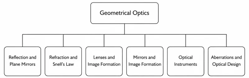
This simple tree chart shows the page structure for the Geometrical Optics section. The hub page, Geometrical Optics, appears at the top, with six subpages arranged beneath it: Reflection and Plane Mirrors, Refraction and Snell’s Law, Lenses and Image Formation, Mirrors and Image Formation, Optical Instruments, and Aberrations and Optical Design. It helps students see how the topic is organised before exploring each page in detail.
The Chronology of Reflection: History, Technical Milestones, and Modern Frontiers
The Historical Journey
Modern Physics Challenges
Future Horizons: Metamaterial Retroreflectors and Dynamic Mirrors
- Digital Micromirror Devices (DMDs): Modern optical systems manipulate light using microchips covered in millions of microscopic, hinges-mounted aluminum mirrors. These micro-elements tilt thousands of times per second via digital logic, modulating light fields dynamically for high-resolution projection and structured advanced illumination.
- Metasurface Phase-Shifting Arrays: Instead of relying on physical surface tilt angles to change a ray’s direction, engineers are creating sub-wavelength flat surfaces engineered with nanoscale pillars. These metasurfaces shift the phase of incoming light directly, enabling flat mirrors to reflect light at customized, arbitrary angles completely independent of the classical law of reflection.
What Reflection Really Is
Regular Reflection
Regular reflection occurs when light reflects from a smooth surface such as a mirror, calm water, polished metal, or glossy glass. The reflected rays remain well organised, so a clear image can be formed.
Diffuse Reflection
Diffuse reflection occurs when light reflects from a rough surface such as paper, cloth, painted walls, or unpolished wood. The reflected rays scatter in many directions, allowing us to see the surface but not a clear mirror image.
Why Smoothness Matters
A surface only needs to be smooth compared with the wavelength of visible light to act like a good mirror. A surface that looks smooth to the hand may still scatter light if it is microscopically uneven.
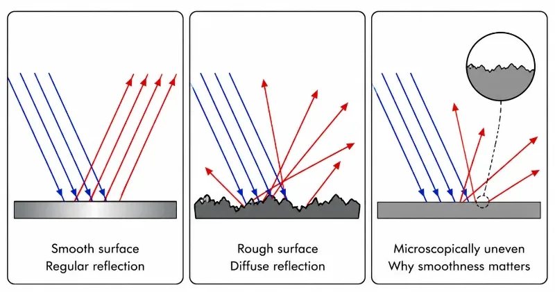
This simple educational illustration shows three panels side by side to explain what reflection really is. In the first panel, parallel incident rays strike a smooth surface and reflect in an orderly way, showing regular reflection. In the second panel, the same incoming rays strike a rough surface and scatter in different directions, showing diffuse reflection. In the third panel, the surface appears smooth at first glance but is shown as microscopically uneven, helping students understand why true smoothness matters for clear reflection. The picture gives students an immediate visual comparison between specular reflection, diffuse reflection, and the microscopic surface features that determine how light behaves.
The Law of Reflection
Important Parts of a Reflection Diagram
Incident Ray
The incident ray is the incoming ray of light that travels toward the reflecting surface.
Reflected Ray
The reflected ray is the outgoing ray of light that leaves the surface after reflection.
Normal
The normal is a line drawn at right angles to the mirror surface. It is the reference line from which the angles of incidence and reflection are measured.
Angle of Incidence
The angle of incidence is the angle between the incident ray and the normal.
Angle of Reflection
The angle of reflection is the angle between the reflected ray and the normal.
Point of Incidence
The point of incidence is the point where the incoming ray strikes the reflecting surface.
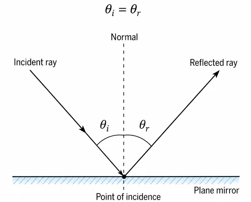
This picture presents a clean diagram of the law of reflection for a plane mirror. It labels the important parts of a reflection diagram, including the incident ray, reflected ray, normal, point of incidence, and plane mirror. The equal angles θ_i and θ_r are shown on either side of the normal to make clear that the angle of incidence is equal to the angle of reflection. The image helps students understand both the geometry of reflection and the correct way to measure the angles in optics.
Plane Mirrors and Virtual Images
- The image is upright.
- The image is the same size as the object.
- The image is virtual.
- The image appears the same distance behind the mirror as the object is in front of the mirror.
- The image is laterally inverted, meaning left and right appear reversed from the viewer’s perspective.
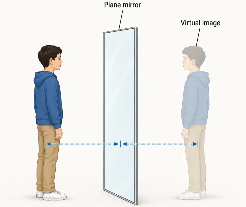
This illustration shows a person standing in front of a plane mirror, with a faint virtual image appearing behind the mirror. The dashed distance markers are placed around knee height and meet at the middle of the mirror, helping students see that the object distance in front of the mirror is equal to the image distance behind the mirror. The picture provides a simple visual introduction to virtual image formation in a plane mirror.
Ray Diagrams for Plane Mirrors
Steps for Drawing a Plane Mirror Ray Diagram
- Draw the plane mirror as a straight vertical line.
- Place the object in front of the mirror.
- Choose at least two points on the object, such as the top of an arrow.
- Draw two rays from that point to the mirror.
- Reflect each ray using the law of reflection.
- Extend the reflected rays backward using dotted lines.
- The point where the backward extensions meet is the position of the virtual image point.
- Repeat for other points if needed, then complete the image behind the mirror.
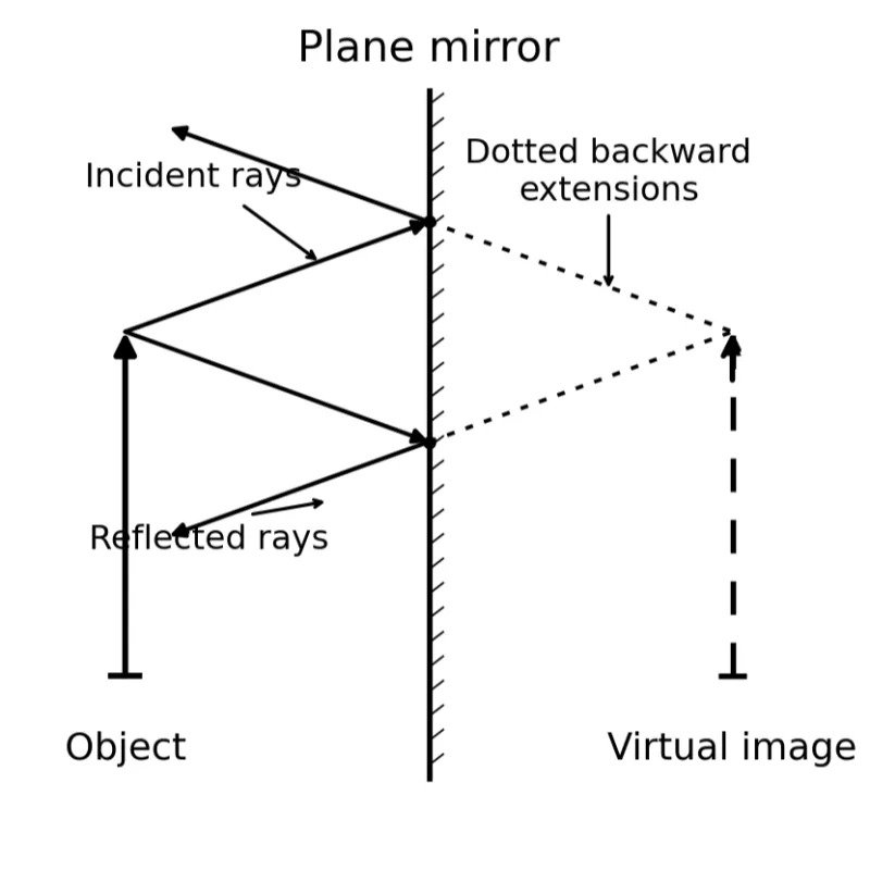
This simple line drawing illustrates how to construct a ray diagram for a plane mirror. Two incident rays from the top of the object arrow strike the mirror and reflect back into the object side. The reflected rays are extended backward using dotted construction lines, and these extensions meet at the top of the virtual image behind the mirror. The diagram helps students understand that the virtual image is not formed by real rays meeting behind the mirror, but by the apparent origin of the reflected rays.
Why the Image Appears Behind the Mirror
Mathematical Summary
Law of Reflection
The incoming and outgoing rays make equal angles with the normal line.
Object and Image Distance
The image track appears exactly as far behind the mirror boundary as the object is positioned in front of it.
Magnification
The virtual representation formed by flat reflection perfectly preserves real object dimensions.
Rigorous Technical Worked Examples
Worked Example 1: Angle of Reflection
Solution:By the foundational law of reflection:$$\theta_i = \theta_r$$Since the text explicitly states the angle of incidence relative to the normal line is 35°, the structural reflection parameter evaluates to:$$\theta_r = 35^{\circ}$$Answer: The angle of reflection is 35°.Key lesson: The angle must always be measured from the normal line, never from the flat mirror surface itself.
Worked Example 2: Object and Image Distance
Solution:For any flat specular boundary:$$d_i = d_o$$The object coordinate is:$$d_o = 1.8\text{ m}$$Therefore, the image coordinate resolves to:$$d_i = 1.8\text{ m}$$Answer: The image appears 1.8 m behind the mirror surface.Key lesson: The complete structural spatial distance between the observer and their virtual image is $1.8\text{ m} + 1.8\text{ m} = 3.6\text{ m}$.
Worked Example 3: Minimum Mirror Height
Solution:By tracking geometric light vectors, the minimum physical mirror vertical height requires half the structural stature of the observer:$$\text{Height}_{\text{mirror}} = \frac{1}{2} \cdot \text{Height}_{\text{object}}$$$$\text{Height}_{\text{mirror}} = \frac{1}{2}(1.70\text{ m}) = 0.85\text{ m}$$Answer: The minimum mirror height is 0.85 m.Key lesson: A full-body view does not require a mirror as tall as the human target. It only requires a vertical span of exactly half the subject’s height, provided its alignment placement is correct.
Everyday Applications of Reflection and Plane Mirrors
Bathroom and Dressing Mirrors
Plane mirrors allow people to see upright virtual images of themselves. The image appears behind the mirror and is the same size as the object.
Periscopes
Simple periscopes use plane mirrors to redirect light around obstacles. This allows an observer to see over walls, around corners, or from a hidden position.
Optical Alignment
Plane mirrors are used in laboratories and engineering systems to guide beams of light along precise paths.
Interior Design
Large mirrors can make rooms appear visually larger by creating virtual space behind the mirror surface.
Vehicles and Safety
Flat mirrors may be used where undistorted size and distance are important. Curved mirrors are used when a wider field of view is needed.
Scientific Instruments
Plane mirrors help redirect light inside optical instruments, telescopes, interferometers, cameras, and beam-steering systems.
Common Misconceptions About Plane Mirrors
Misconception 1: The Image Is on the Mirror Surface
The image appears behind the mirror, not on the surface. The mirror surface redirects light, while the brain traces the reflected rays backward.
Misconception 2: A Plane Mirror Reverses Top and Bottom
A plane mirror does not reverse top and bottom. What students often call left-right reversal is better understood as front-back reversal relative to the mirror.
Misconception 3: Rays Really Travel Behind the Mirror
The rays do not actually pass through the mirror. The dotted rays behind the mirror in a ray diagram are backward extensions used to locate the virtual image.
Misconception 4: A Larger Mirror Makes a Larger Image
A plane mirror does not magnify. A larger mirror may allow you to see more of the object, but the image size remains the same as the object size.
Misconception 5: The Image Distance Depends on the Viewer
The image position depends on the object position relative to the mirror, not on where the observer stands. The observer’s position only affects which reflected rays enter the eye.
Misconception 6: Reflection Only Happens in Mirrors
Reflection occurs from many surfaces. Mirrors produce clear images because their surfaces are smooth enough to reflect light regularly.
Connection to Later Topics
Curved Mirrors
Curved mirrors still obey the law of reflection, but their changing surface direction allows them to converge or diverge light rays.
Lenses
Lenses use refraction rather than reflection, but they also form images using predictable ray paths.
Optical Instruments
Many optical instruments combine reflection and refraction to guide light, magnify images, or improve visibility.
Fiber Optics
Optical fibres rely on repeated internal reflection to guide light over long distances.
Quick Check: Concepts and Calculations
$$\theta_i = 90^{\circ} – 25^{\circ} = 65^{\circ}$$
By the law of reflection, $\theta_r = \theta_i = 65^{\circ}$.
$$\text{Speed}_{\text{relative}} = 2.0\text{ m/s} + 2.0\text{ m/s} = 4.0\text{ m/s}$$
Review Questions and Answers
Thought-Provoking Questions and Answers
Comprehensive Numerical Problems with Solutions
Solution:$$\theta_r = \theta_i = 20^{\circ}$$Answer: 20°
Solution:The normal axis sits at 90° relative to the surface plane:$$\theta_i = 90^{\circ} – 60^{\circ} = 30^{\circ}$$Answer: The angle of incidence is 30°.
Solution:$$d_i = d_o = 2.5\text{ m}$$Answer: The image forms exactly 2.5 m behind the mirror surface plane.
Solution:The virtual image maps at an identical depth coordinate behind the glass boundary ($d_i = 1.2\text{ m}$):$$\text{Distance}_{\text{total}} = d_o + d_i = 1.2\text{ m} + 1.2\text{ m} = 2.4\text{ m}$$Answer: 2.4 m
Solution:$$\text{Height}_{\text{mirror}} = \frac{1}{2} \cdot \text{Height}_{\text{object}} = \frac{1}{2}(1.60\text{ m}) = 0.80\text{ m}$$Answer: 0.80 m
Solution:Because flat mirrors feature a magnification factor of exactly $M = 1$:$$h_i = h_o = 12\text{ cm}$$Answer: The image is 12 cm tall.
Glossary
Angle of Incidence (θi)
The geometric angle measured between the incoming light path vector and the surface normal line.
Angle of Reflection (θr)
The geometric angle measured between the exiting reflected light path vector and the surface normal line.
Diffuse Reflection
Scattered reflection of light fields off a textured, microscopically rough interface.
Incident Ray
The tracking line modeling incoming light moving toward an optical boundary layer.
Normal
An imaginary reference baseline vector constructed perpendicular ($90^{\circ}$) to a surface interface.
Plane Mirror
A completely flat, highly polished mirror that reflects light fields without introducing geometric distortion.
Reflected Ray
The tracking line modeling exiting light moving away from an optical reflection interface.
Regular (Specular) Reflection
Orderly, uniform reflection of light waves off an even, highly smooth surface, creating a distinct image map.
Reflection
The physical process where a wave boundary interaction turns light energy back into its original medium.
Virtual Image
An optical map located by tracing diverging light tracks back to an apparent crossing point behind a boundary surface.
External References
- OpenStax College Physics 2e – Reflection and Mirror Rules
- Physics LibreTexts – Flat Reflection Geometries
- The Physics Classroom – The Mechanics and Mathematics of the Law of Reflection