
In the simplest ray diagrams, lenses and mirrors often seem perfect. Rays meet neatly at one point, images are sharp, colours overlap exactly, and every part of the image looks faithful to the object. Real optical systems are more complicated. A lens may blur the edge of an image, separate colours slightly, stretch straight lines, or make off-centre points look like small smudges instead of clean dots. These imperfections are called optical aberrations.
Aberrations do not mean that lenses are poorly made. They arise because real lenses have size, thickness, curvature, material properties, and practical limits. A classroom ray diagram is useful because it reveals the main idea of image formation under the paraxial approximation (assuming rays stay very close to the optical axis), but real-world engineering asks a deeper question: how can we make real images as sharp, bright, accurate, and useful as possible?
This page introduces aberrations and optical design as a bridge between basic geometrical optics and real optical instruments. It helps students understand why cameras use several lens elements, why telescopes and microscopes require careful alignment, why spectacles must be designed for both clarity and comfort, and why modern imaging systems combine physics, engineering, materials science, and computation.
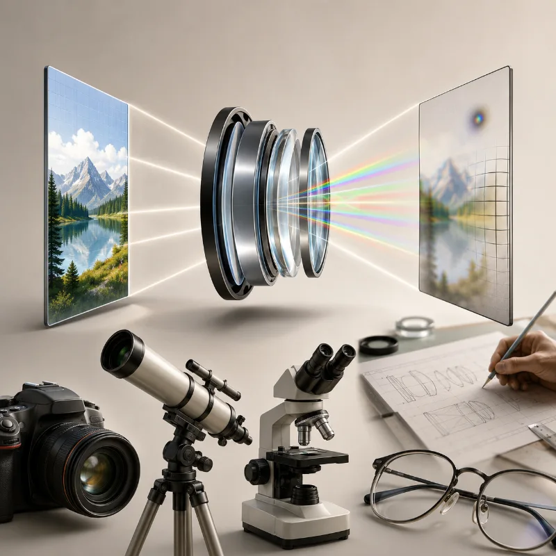
This artist impression introduces optical aberrations and optical design through a real-world imaging scene. A multi-element lens system is shown between an ideal object image and an imperfect projected image, suggesting how real lenses can produce blur, colour separation, edge distortion, and off-centre smudging. Cameras, telescopes, microscopes, spectacles, and design sketches appear around the scene to show that optical design connects classroom ray diagrams with practical instruments used in photography, astronomy, microscopy, vision correction, and engineering.
How This Page Fits into Geometrical Optics
Aberrations and optical design build on the basic ideas of reflection, refraction, lenses, mirrors, and image formation. Once students understand how ideal rays form ideal images, they can begin to ask why real images are sometimes imperfect and how designers reduce those imperfections.
Light and Optics
Provides the wider foundation for studying light, reflection, refraction, lenses, mirrors, wave behaviour, and optical instruments.Geometrical Optics
Uses rays, straight-line paths, reflection, and refraction to explain how images are formed by mirrors, lenses, and optical systems.Reflection
Explains how light changes direction at surfaces, supporting later study of mirror design and image imperfections.Refraction
Shows how light bends when it enters a different medium, which is central to understanding lenses and chromatic aberration.Lenses and Image Formation
Introduces how lenses bring rays together or spread them apart to form real and virtual images.Mirrors and Image Formation
Explains how plane, concave, and convex mirrors form real or virtual images through reflection and ray tracing.Aberrations and Optical Design
Examines why real images differ from ideal ray diagrams and how optical systems are designed to reduce blur, colour error, distortion, and field defects.Optical Instruments
Applies optical design ideas to cameras, microscopes, telescopes, projectors, spectacles, and the human eye.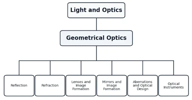
The Evolution of Optical Design: History, Challenges, and Future
Optical design has evolved from a game of trial-and-error by early artisans into a highly sophisticated branch of applied physics and computational engineering.
The Historical Journey
Early telescope makers like Galileo Galilei and Johannes Kepler were severely limited by aberrations. Galileo’s refracting telescope suffered from heavy colour fringing. In 1668, Sir Isaac Newton invented the reflecting telescope out of frustration, believing that chromatic aberration was an insurmountable physical limitation of glass lenses.
The breakthrough came in 1729 when Chester Moore Hall (and later John Dollond) discovered that combining different glass types could cancel out colour errors, leading to the achromatic doublet. By the mid-19th century, Ludwig von Seidel mathematically categorized the five primary monochromatic aberrations, giving engineers the equations needed to design complex systems systematically rather than guessing.
Contemporary Engineering Challenges
Today, the primary challenge is pushing the physical boundaries of miniaturization and extreme performance. Smartphone cameras demand ultra-sharp, wide-angle images from arrays of plastic elements less than 5 mm thick. Conversely, lithography systems used to print silicon microchips require near-perfect optics operating at extreme ultraviolet wavelengths, where even an atomic-scale error in surface smoothness renders the system useless.
The Future: Meta-Optics and Computational Imaging
The future of optical design is splitting into two exciting frontiers:
- Flat Optics (Metalenses): Instead of thick, curved glass, engineers are designing flat surfaces engineered with nanoscale structures (metasurfaces) that manipulate the phase, amplitude, and polarization of light directly. This could make bulky lenses completely obsolete.
- Co-Design of Optics and AI: Modern cameras no longer rely solely on physical lenses. Optical designers now build lenses alongside neural networks. The hardware purposefully leaves in certain benign aberrations, knowing that machine-learning algorithms can perfectly reconstruct a crystal-clear image instantly, cutting down the weight and cost of the physical glass.
What Optical Aberrations Really Are
An optical aberration is a systematic departure from ideal image formation. In an ideal paraxial lens system, first-order approximation assumes that sin θ ≈ θ. Under this assumption, light from one point on an object is brought to one perfect point in the image plane.
However, when we look at higher-order approximations by expanding the sine function into a Taylor series:
$$\sin \theta = \theta – \frac{\theta^3}{3!} + \frac{\theta^5}{5!} – \dots$$
The third-order term (-θ³/6) introduces deviations from paraxial theory. These deviations are mathematically known as the Seidel Aberrations. The result is that rays traveling far from the axis or at steep angles fail to converge at a single geometric coordinate.
The important idea is that aberration is not simply “bad focus.” A blurred photograph can be caused by poor focusing, camera shake, motion, sensor noise, or low resolution. Aberration is more specific: it is caused by how the optical system bends or reflects rays. Even when a lens is carefully focused, some rays may still fail to meet exactly where the simple theory predicts.
Optical design is the art and science of controlling these errors. Designers adjust lens shape, curvature, spacing, material, aperture size, and lens combinations so that the final image is good enough for its intended purpose. A microscope, a mobile phone camera, a telescope, and a pair of spectacles do not need the same design. Each system has its own priorities.
Ideal Ray Diagrams and Real Optical Systems
A simple ray diagram usually assumes a thin lens, small angles, rays close to the principal axis, and one wavelength of light. These assumptions make the mathematics and geometry manageable. They are very useful for learning image position, magnification, real images, virtual images, and focal points.
However, real optical systems must handle wide beams, different colours, off-axis objects, curved surfaces, finite lens thickness, and practical manufacturing limits. When these real conditions are included, the neat behaviour of ideal rays becomes less perfect.
| Ideal Ray Diagram (Paraxial) | Real Optical System (Third-Order / Real Rays) |
|---|---|
| Rays from one object point meet at one perfect image point. | Rays may meet over a small region, causing blur. |
| All colours are treated as if they bend in the same way. | Different wavelengths refract by slightly different amounts due to material dispersion. |
| Only rays near the principal axis are considered (sin θ ≈ θ). | Real lenses must handle rays far from the axis where sin θ ≈ θ – θ³/6. |
| The lens is treated as infinitely thin. | Real lenses have thickness, internal surface radii, and mechanical mounting alignment tolerances. |
| The image surface is imagined as flat and perfect. | The sharpest image surface may be inherently curved (Petzval surface). |
Major Types of Optical Aberration
Different aberrations affect images in different ways. Some mainly blur the centre of the image, some affect the edges, some create colour fringes, and some change the shape of objects. Learning these types helps students see why optical design is not just about choosing a focal length.
Spherical Aberration
Occurs when rays passing through the outer zones of a spherical lens or mirror focus closer to the lens than rays near the centre. The image looks soft even near the middle.Chromatic Aberration
Occurs because different colours of light refract by slightly different amounts. It produces coloured fringes around bright edges.Coma
Affects off-axis points, making them appear like small comet-shaped smears instead of sharp dots. It is highly sensitive to the angle of incoming light.Astigmatism
Occurs when rays in the sagittal and tangential planes focus at different distances, stretching a point into an ellipse or line.Field Curvature
Occurs when the sharpest image does not lie on a flat surface, meaning the centre may be sharp while the edges are out of focus.Distortion
Changes image geometry without reducing image sharpness. Straight lines bow outward (barrel) or inward (pincushion).Spherical Aberration
Spherical aberration happens because spherical surfaces do not bring all parallel rays to the same focus. Rays passing near the edge of a lens may be bent more strongly or differently than rays passing close to the centre. Instead of forming one sharp focal point, the rays form a small blurred region.
This effect is especially noticeable when a lens or mirror uses a wide aperture. A wide aperture allows more light to enter, but it also admits more edge rays. If those edge rays do not focus at the same point as central rays, the image becomes less sharp.
Optical designers reduce spherical aberration by using aperture stops, combining lenses, changing surface curvature, or using aspheric surfaces. An aspheric surface is not part of a simple sphere. It is shaped more carefully so that rays from different zones can be brought closer to a common focus.
Mathematical Principle & Numerical Example
The longitudinal spherical aberration (LSA), which is the distance along the optical axis between the paraxial focus and the marginal focus, scales with the square of the aperture diameter (D²). The transverse spherical aberration (TSA), representing the blur radius at the paraxial plane, scales with the cube of the diameter (D³).
$$TSA \propto D^3 \cdot \frac{1}{f^2}$$
Numerical Example:A simple plano-convex lens has a transverse spherical aberration blur diameter of 0.08 mm when used at an aperture diameter of 20 mm. If the aperture is opened up to a diameter of 40 mm, what will be the new blur diameter due to spherical aberration?Solution:Since TSA α D³, we can set up a ratio:$$\frac{TSA_2}{TSA_1} = \left(\frac{D_2}{D_1}\right)^3$$$$\frac{TSA_2}{0.08\text{ mm}} = \left(\frac{40}{20}\right)^3 = 2^3 = 8$$$$TSA_2 = 0.08\text{ mm} \times 8 = 0.64\text{ mm}$$Answer: Doubling the aperture diameter increases the image blur from spherical aberration by a factor of 8, drastically degrading the image quality.
Chromatic Aberration
Chromatic aberration is connected to dispersion. When white light enters glass or plastic, different wavelengths bend by slightly different amounts. Blue light and red light may therefore focus at different distances. This can produce colour fringes, especially around bright objects against dark backgrounds.
A simple single lens is more likely to show chromatic aberration. A common correction method is to combine two lenses made from different kinds of glass. Such a combination can bring two colours closer to the same focus and reduce the visible colour error. This is the basic idea behind an achromatic lens.
Modern camera lenses, microscope objectives, and telescope eyepieces often use several elements to control colour error. In advanced systems, optical coatings and carefully selected materials also help maintain contrast, reduce reflections, and improve image quality.
Mathematical Principle & Numerical Example
Chromatic aberration occurs because glass has a changing index of refraction across different wavelengths, quantified by the Abbe Number (V):
$$V = \frac{n_{\text{yellow}} – 1}{n_{\text{blue}} – n_{\text{red}}}$$
For a single thin lens, the longitudinal chromatic aberration (LCA), which is the distance between the red and blue focal points, is given by LCA = f / V. To eliminate this error completely, designers pair a positive crown glass lens with a negative flint glass lens to form an achromatic doublet. The total power (P = 1/f) of the combination must satisfy:
$$P_{\text{total}} = P_1 + P_2 \quad \text{and} \quad \frac{P_1}{V_1} + \frac{P_2}{V_2} = 0$$
Numerical Example:You need to design an achromatic doublet with a net focal length of 50 cm (Ptotal = +2.0 dioptres). Element 1 is made of crown glass (V1 = 60) and Element 2 is made of flint glass (V2 = 36). Calculate the required focal lengths for each lens element.Solution:1. Set up the equations using powers:$$P_1 + P_2 = 2$$$$\frac{P_1}{60} + \frac{P_2}{36} = 0 \Rightarrow P_2 = -\frac{36}{60}P_1 = -0.6P_1$$2. Substitute P₂ into the total power equation:$$P_1 – 0.6P_1 = 2 \Rightarrow 0.4P_1 = 2 \Rightarrow P_1 = +5.0\text{ dioptres}$$3. Solve for P₂:$$P_2 = 2 – 5.0 = -3.0\text{ dioptres}$$4. Convert powers back to focal lengths (f = 1/P):$$f_1 = \frac{1}{5.0} = +0.2\text{ m} = +20\text{ cm}$$$$f_2 = \frac{1}{-3.0} = -0.333\text{ m} = -33.3\text{ cm}$$
Answer: The doublet requires a convex crown lens of f = +20 cm and a concave flint lens of f = -33.3 cm.
Coma, Astigmatism, and Off-Axis Image Quality
Many optical problems become more obvious away from the centre of the image. A lens may form a fairly sharp image near the principal axis but show visible defects near the edges. This matters because real photographs, telescope views, and microscope images are not limited to one point at the centre.
Coma makes off-axis objects appear like small asymmetric smears. Astigmatism causes rays in different planes to focus at different distances, so a point may appear stretched. These defects are important in lenses that need a wide field of view, such as camera lenses, astronomical instruments, and projection systems.
Correcting these aberrations usually requires more than one lens surface. Designers may combine several elements, adjust spacing, use special glass types, and limit the useful aperture or field angle. The goal is not always to remove every aberration completely, but to reduce them enough for the intended use.
Field Curvature and Distortion
Field curvature means that the best image surface is curved rather than flat. This becomes a problem when the image must fall on a flat sensor, flat film, or flat screen. If the centre is focused sharply, the edges may be slightly out of focus. If the edges are focused, the centre may become less sharp.
Distortion is different because it changes shape rather than focus. In barrel distortion, straight lines near the edge of the image appear to bulge outward. In pincushion distortion, they appear to bend inward. The image may still look sharp, but its geometry is not faithful.
Distortion is especially important in photography, surveying, machine vision, and scientific imaging, where shape and measurement matter. In some modern systems, optical design reduces distortion physically, while software correction handles the remaining error after the image is captured.
The radius of curvature of the curved field (Rp) for thin lenses in contact is determined by the Petzval Theorem:
$$\frac{1}{R_p} = \frac{1}{n_1 f_1} + \frac{1}{n_2 f_2}$$
Geometric distortion shifts image points away from their true predicted coordinate without altering focal sharpness, calculated as:
$$\text{Distortion } \% = \frac{h_{\text{actual}} – h_{\text{predicted}}}{h_{\text{predicted}}} \times 100$$
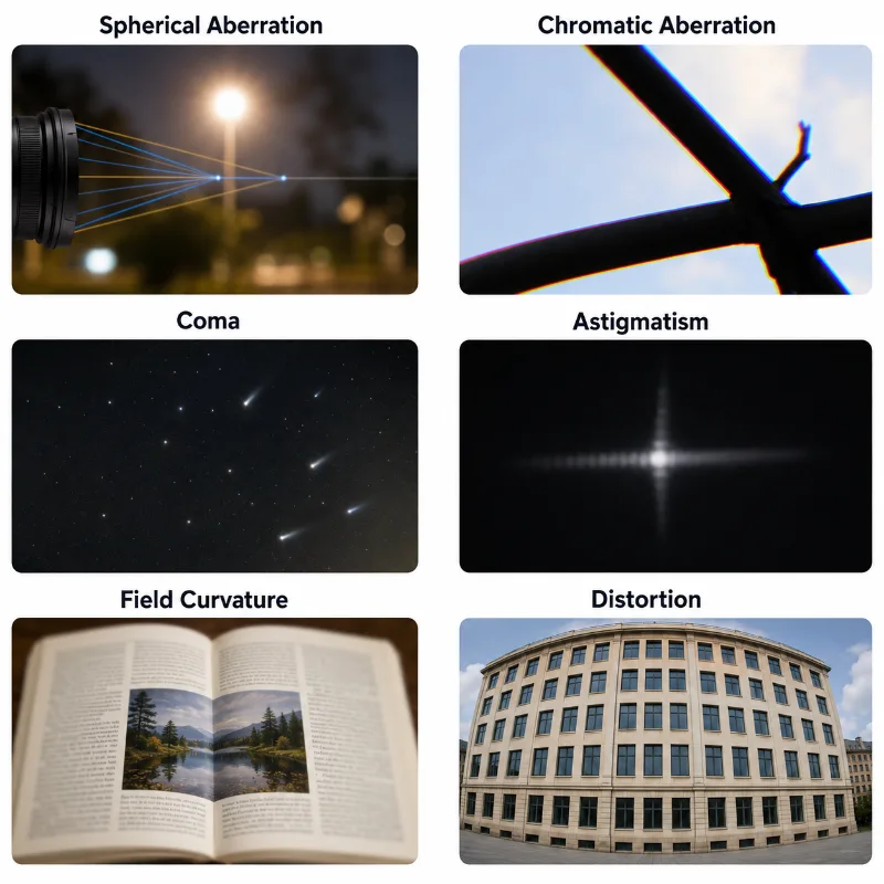
This educational image presents six artist’s impressions of common optical aberrations. Spherical aberration is shown through soft focusing of light, chromatic aberration through coloured fringes, coma through comet-like off-centre points, astigmatism through an unevenly stretched point image, field curvature through uneven sharpness across an open page, and distortion through a building whose straight lines appear bent. The layout helps students compare the main visual effects of each aberration at a glance.
How Optical Designers Reduce Aberrations
Optical design is a process of controlled compromise. Designers rarely improve one property without affecting another. A lens that is brighter may be larger, heavier, more expensive, or more difficult to correct. A lens with excellent sharpness at the centre may need additional design work to remain sharp at the edges. A compact lens may require more correction in software.
| Design Method | How It Helps | Possible Trade-Off |
|---|---|---|
| Stopping down the aperture | Blocks outer rays that often contribute strongly to blur and third-order Seidel errors. | Reduces brightness, requires longer exposure, and increases diffraction limits. |
| Using multiple lens elements | Allows one element to compensate for the errors of another. | Increases cost, weight, thickness, reflection losses, and alignment complexity. |
| Using different glass materials | Helps control chromatic aberration and dispersion profiles. | May increase manufacturing cost or limit design choices. |
| Using aspheric surfaces | Reduces spherical aberration completely and can improve compact designs. | Requires more complex manufacturing, diamond turning, and testing. |
| Applying optical coatings | Reduces unwanted reflection and improves contrast. | Requires careful material and layer thickness selection. |
| Using software correction | Can reduce distortion, colour fringing, and edge shading after capture. | May crop the image or reduce fine structural spatial resolution. |
Optical Design as a Balance of Priorities
There is no single “best” lens for every purpose. A portrait lens, a microscope objective, a telescope eyepiece, a smartphone camera, and a spectacle lens are designed for different conditions. Each must balance sharpness, brightness, field of view, distortion, size, cost, weight, durability, and ease of use.
For example, a telescope may prioritise faint-light collection and sharp star images. A smartphone camera may prioritise compactness, fast focusing, and software correction. A microscope objective may prioritise high numerical aperture, resolution, and correction over a small field. Spectacle lenses must balance optical clarity with comfort, thickness, appearance, and the wearer’s eye movement.
This is why optical design is both scientific and practical. It begins with the physics of light, but it ends with human needs: seeing clearly, recording accurately, measuring reliably, and building instruments that can actually be used.
A Simple Numerical Dimension: Aperture and Brightness
A useful way to understand optical design is to compare aperture size with brightness and sharpness. The aperture is the opening that allows light into an optical system. A larger aperture collects more light, but it may also make some aberrations more visible.
For a circular aperture, the light-gathering area is proportional to the square of its diameter:
$$A \propto D^2$$
This means that doubling the aperture diameter allows about four times as much light to enter. However, a larger aperture also admits rays farther from the principal axis. These outer rays are often more difficult to focus perfectly, so the designer must balance brightness against aberration control.
In photography, the f-number is commonly written as:
$$N = \frac{f}{D}$$
Here, N is the f-number, f is the focal length, and D is the aperture diameter. A smaller f-number means a larger aperture and more light, but it can also make optical defects and focusing errors more noticeable.
Worked Example: Why Stopping Down Can Improve Sharpness
Problem: A camera lens produces a slightly soft image when used at a very wide aperture. When the aperture is made smaller, the image becomes sharper. Explain why this can happen.
Solution: A wide aperture allows rays from the outer parts of the lens to enter. These outer rays are more likely to contribute to spherical aberration and other off-axis defects. When the aperture is reduced, some of these outer rays are blocked. The image may become sharper because the remaining rays come from a smaller and better-controlled region of the lens.
Answer: Stopping down can improve sharpness because it reduces the contribution of rays that are harder for the lens to focus accurately. The trade-off is that less light reaches the image sensor or screen.
Real-World Applications
Aberrations and optical design appear wherever people need clear, accurate, or useful images. The topic is not limited to specialist laboratories. It affects everyday photography, medical imaging, astronomy, manufacturing, vision correction, and classroom projection.
Cameras and Smartphones
Camera lenses must balance sharpness, brightness, colour correction, distortion, size, and cost. Smartphone cameras often combine small lenses with software correction.Microscopes
Microscope objectives require careful correction because small details must be magnified without losing resolution, contrast, or colour accuracy.Telescopes
Astronomical instruments must reduce aberrations so that stars remain sharp and faint objects can be observed clearly across the field of view.Spectacles and Contact Lenses
Corrective lenses must improve focus while remaining comfortable, wearable, and visually acceptable for everyday use.Projectors
Projection lenses must produce a bright, sharp image over a large flat screen, while controlling distortion and edge blur.Machine Vision
Industrial inspection systems need accurate images because optical distortion can affect measurement, alignment, and quality control.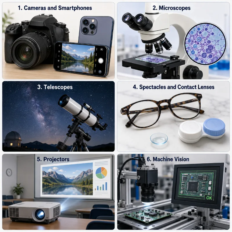
This six-panel artist impression shows real-world applications of aberrations and optical design. Cameras and smartphones depend on lens correction and software processing to balance sharpness, colour, distortion, and compactness. Microscopes require corrected optics to reveal fine biological details clearly. Telescopes need careful aberration control so stars remain sharp across the field of view. Spectacles and contact lenses improve vision while remaining comfortable for daily use. Projectors must produce bright, sharp images on large screens, while machine vision systems rely on accurate imaging for inspection, measurement, and industrial quality control.
Common Misconceptions about Aberrations
Misconception 1: Aberration Means the Lens Is Broken
Aberration does not usually mean that the lens is damaged. It often arises naturally from the shape, size, material, and geometry of the optical system. Even a well-made lens can show aberrations if used under demanding conditions.
Misconception 2: A Sharper Centre Means the Whole Image Is Sharp
The centre of an image may be sharp while the edges are less clear. Off-axis aberrations such as coma, astigmatism, field curvature, and distortion often become more noticeable away from the centre.
Misconception 3: More Lens Elements Always Mean a Better Lens
More elements can help correct aberrations, but they can also increase cost, weight, reflection losses, alignment difficulty, and manufacturing complexity. Good design depends on purpose, not simply on the number of elements.
Misconception 4: Software Correction Replaces Optical Design
Software can correct some image defects after capture, especially distortion and colour fringing. However, it cannot fully recover information that was never sharply focused or properly recorded. Optical design and digital processing work best together.
Misconception 5: Perfect Images Are Always the Goal
In practice, optical systems are designed to be good enough for their purpose. A scientific imaging system may require strict correction, while an everyday camera lens may accept small imperfections in exchange for compactness, affordability, or speed.
Quick Check: Common Misconceptions about Aberrations
1. Does optical aberration always mean that a lens is broken or damaged?
A. Yes, aberration always means the lens is physically damaged.
B. No, aberration can arise naturally from lens shape, size, material, and optical geometry.
C. Yes, aberration only appears in old or dirty lenses.
D. No, aberration only happens in mirrors, not lenses.
Answer: B. Aberration does not usually mean that the lens is broken. Even a well-made lens can show aberrations because real lenses have curvature, thickness, material properties, aperture size, and practical design limits.
2. If the centre of an image is sharp, does that guarantee that the whole image is sharp?
A. Yes, centre sharpness always means the whole image is sharp.
B. No, the edges may still show coma, astigmatism, field curvature, or distortion.
C. Yes, aberrations only affect the centre of the image.
D. No, but only colour can change at the edge.
Answer: B. A lens may form a sharp image near the centre while the edges remain less clear. Off-axis aberrations often become more noticeable away from the principal axis.
3. Do more lens elements always produce a better optical system?
A. Yes, the lens with the most elements is always best.
B. No, more elements can help correction but may also increase cost, weight, reflection losses, and alignment difficulty.
C. Yes, more elements remove all aberrations completely.
D. No, because lens elements have no effect on image quality.
Answer: B. More lens elements can help reduce aberrations, but they also introduce trade-offs. Good optical design depends on the purpose of the instrument, not simply on the number of lens elements.
4. Can software correction completely replace good optical design?
A. Yes, software can fully recover any optical detail after capture.
B. No, software can correct some defects, but it cannot fully recover information that was never sharply focused or recorded.
C. Yes, optical design is no longer needed in modern imaging.
D. No, software can only correct lens colour, not image geometry.
Answer: B. Software can reduce some problems such as distortion or colour fringing, but it cannot fully restore detail that the optical system failed to focus or capture. Optical design and digital processing work best together.
5. Is a perfectly corrected image always the main goal of optical design?
A. Yes, every optical system must remove every imperfection.
B. No, optical systems are usually designed to be good enough for their purpose while balancing size, cost, brightness, sharpness, and usability.
C. Yes, small imperfections are never acceptable.
D. No, because optical design only concerns lens appearance.
Answer: B. Optical design is often about balancing trade-offs. A scientific imaging system may need very strict correction, while an everyday camera lens may accept small imperfections in exchange for compactness, speed, affordability, or ease of use.
Review Questions and Answers
1. What is an optical aberration?
Answer: An optical aberration is a departure from ideal image formation. It occurs when rays do not form the perfectly sharp, faithful image predicted by simple paraxial ray diagrams.
2. Why do real lenses show aberrations?
Answer: Real lenses have finite size, thickness, curvature, material properties, and practical limitations. These factors can cause different rays or colours to focus differently.
3. What is spherical aberration?
Answer: Spherical aberration occurs when rays passing through different zones of a spherical lens or mirror focus at different distances. Outer marginal rays typically bend more severely than central ones.
4. What causes chromatic aberration?
Answer: Chromatic aberration is caused by dispersion, where a lens material possesses a changing refractive index across different wavelengths. This makes different colours (wavelengths) focus at slightly different positions.
5. Why can a smaller aperture improve sharpness?
Answer: A smaller aperture blocks some outer marginal rays that are often more severely affected by third-order aberrations. This makes the remaining ray bundle sharper, although it reduces total light throughput.
6. What is distortion?
Answer: Distortion is an aberration that changes image geometry rather than focus. Straight lines appear curved outward (barrel) or inward (pincushion), even if the image remains highly sharp.
7. Why are several lens elements used in many optical instruments?
Answer: Multiple lens elements allow designers to combine elements of opposite optical powers and different glass properties, systematically forcing one element to compensate for the aberration errors of another.
8. Why is optical design a compromise?
Answer: Improving one design parameter, such as aperture speed or compactness, systematically increases other errors like spherical blur or edge distortion, requiring a structured balance of trade-offs.
Thought-Provoking Questions with Answers
1. Why might an expensive lens still show some aberration?
Answer: No real lens is perfectly ideal under all conditions. Even an expensive lens is designed around specific architectural priorities such as ultra-wide apertures, specialized fields of view, or light weight. Some residual aberration is deliberately left behind because absolute correction across all metrics is physically impossible.
2. Why is the edge of an image often harder to correct than the centre?
Answer: Rays originating from off-axis object points strike the lens at varied oblique angles. This asymmetric path creates substantial differences in how the vertical and horizontal planes bend, leading directly to coma, astigmatism, field curvature, and distortion near the edges.
3. Why is chromatic aberration connected to the colour of light?
Answer: Different colours correspond to different optical wavelengths. Because transparent materials exhibit dispersion, the refractive index varies by wavelength—causing blue light to refract more strongly than red light and focus closer to the lens.
4. Why might software correction be acceptable in a smartphone camera but less acceptable in a scientific measuring instrument?
Answer: A smartphone image is designed to look aesthetically pleasing to human viewers, where slight interpolation artifacts are imperceptible. A scientific instrument relies on absolute geometric accuracy and raw pixel values for physical measurement, meaning optical errors must be resolved physically rather than altered digitally.
5. What does optical design teach us about engineering more generally?
Answer: It demonstrates that advanced engineering is essentially the management of complex constraints. A masterful design is not the most complex system imaginable, but the one that most efficiently accomplishes its performance objectives within its physical boundaries.
Glossary
- Abbe Number (V)
- A measure of a transparent material’s dispersion properties; higher values indicate lower chromatic dispersion profiles.
- Achromatic Doublet
- A two-piece lens combination designed to bring two distinct wavelengths (usually red and blue) to the exact same focal point.
- Aperture
- The structural opening through which light bundles enter an optical system.
- Aspheric Surface
- A lens or mirror surface profile that deviates from a perfect sphere, precisely shaped to minimize spherical errors.
- Astigmatism
- An aberration in which rays in different perpendicular planes focus at different axial distances, turning sharp points into ellipses.
- Chromatic Aberration
- An operational defect caused by different wavelengths of light refracting by different amounts due to material dispersion.
- Coma
- An off-axis aberration caused by lateral magnification variations across lens zones, turning points into comet-like streaks.
- Distortion
- An aberration that changes the spatial geometry of the image, causing straight lines to bow outward or inward.
- Field Curvature
- The natural tendency of optical elements to focus images onto a paraboloidal curved surface rather than a flat plane.
- Optical Aberration
- A systematic departure from ideal paraxial image formation caused by the shape, thickness, and wave properties of real systems.
- Optical Design
- The engineering science of calculating and arranging optical components to transmit light with optimal quality and accuracy.
External References
- OpenStax College Physics 2e – Aberrations
- Physics LibreTexts – Introduction to Optical Aberrations
- The Physics Classroom – Spherical Aberration
- Edmund Optics – Comparison of Optical Aberrations Technical Guide
Summary
Aberrations show why real optical systems are more subtle than ideal paraxial ray diagrams. In perfect first-order theory, rays meet precisely at geometric coordinates. In real systems, the non-linear properties of refraction (sin θ ≠ θ) and material dispersion force rays to disperse across space and color spectrums.
Optical engineering uses mathematical tools like the Seidel expansion, special materials like crown and flint pairings, and advanced geometries like aspherics or modern computational post-processing to minimize these errors. The goal is always a tailored balance of performance, weight, cost, and physical feasibility.
Reflection Question
Given that the human eye naturally suffers from both chromatic and spherical aberrations, why do we usually perceive our vision as perfectly sharp and free of color fringes? How does our brain act as the ultimate computational optical element?