Prepare for University Studies & Career Advancement
Refraction and Snell’s Law
Refraction is one of the most important ideas in geometrical optics. It explains why a straw appears bent in water, why a swimming pool may look shallower than it really is, why lenses can focus light, why prisms can separate colours, and why optical fibres can guide light around curves. Whenever light passes from one material into another, its speed changes. If it enters at an angle, its direction also changes.
This bending of light is called refraction. It may look like a simple change in direction, but it is the foundation of many optical technologies. Cameras, spectacles, microscopes, telescopes, projectors, endoscopes, prisms, fibre-optic communication systems, and even the focusing system of the human eye all depend on refraction in one form or another.
Snell’s Law gives a precise mathematical rule for refraction. It connects the angle of incidence, the angle of refraction, and the refractive indices of the two materials. By learning Snell’s Law, students move from simply observing that light bends to predicting how much it bends.
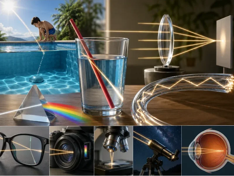
Refraction explains how light bends when it enters a new material, supporting lenses, prisms, optical fibres, cameras, spectacles, microscopes, telescopes, and vision.
This artist impression introduces refraction and Snell’s Law through familiar examples and optical technologies. It shows light bending at a swimming pool surface, a straw appearing bent in water, a prism separating white light into colours, a lens focusing rays, and an optical fibre guiding light along a curved path. The lower panels connect refraction to spectacles, camera lenses, microscopes, telescopes, and the human eye, helping students see how the bending of light becomes the foundation of many real optical systems.
How This Page Fits into Geometrical Optics
Refraction and Snell’s Law belong to geometrical optics because many refraction effects can be understood by drawing light rays. Once students understand how a ray changes direction at a boundary, they can better understand lenses, image formation, prisms, optical fibres, and optical instruments.
Explains why real mirrors and lenses do not form perfect images and how optical design improves clarity and precision.
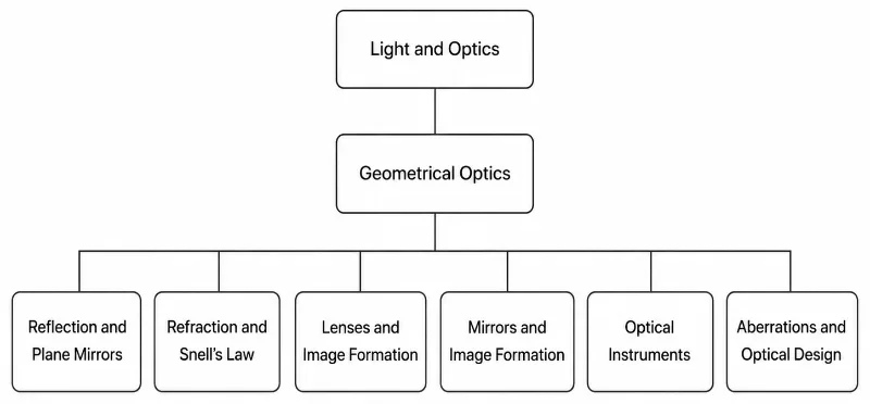
This 1-1-6 tree chart shows how Refraction and Snell’s Law fits within the wider Geometrical Optics cluster.
This clean hierarchy chart presents Refraction and Snell’s Law as part of the Geometrical Optics cluster. Light and Optics appears as the top-level parent, Geometrical Optics appears as the second-level topic, and six related subtopics branch from it: Reflection and Plane Mirrors, Refraction and Snell’s Law, Lenses and Image Formation, Mirrors and Image Formation, Optical Instruments, and Aberrations and Optical Design. The chart helps students see that refraction is studied alongside reflection, image formation, optical instruments, and optical design within the wider structure of geometrical optics.
The Context of Refraction: History, Physical Hurdles, and Future Paradigms
The observation that a medium can alter the path of light has challenged philosophers and physicists for millennia, shifting our view of light from simple straight-line paths into complex wavefront adjustments.
The Historical Journey
The earliest quantified observations of refraction were recorded by Claudius Ptolemy in 150 CE, who mapped out angles of entry between air and water but struggled to determine a universal mathematical pattern. In 984 CE, Persian physicist Ibn Sahl achieved a major breakthrough by documenting how geometric proportions govern light paths through curved crystals, explicitly formulating what is now recognized as the law of refraction.
The mathematical rule was later independently derived in western science by Willebrord Snellius in 1621 (Snell’s Law) and subsequently popularized by René Descartes. In 1662, Pierre de Fermat provided the deep physical explanation through his **Principle of Least Time**, proving that light refracts because it inherently travels along the path that minimizes its total travel time between two coordinates.
Contemporary Scientific Challenges
In basic physics, materials are assumed to possess a constant refractive index. In the real world, however, transparent materials exhibit **dispersion**, where a medium’s index of refraction changes depending on the incoming wavelength of light.
This material variance creates substantial engineering hurdles in instrumentation, causing different spectral colors to focus at distinct spatial points (chromatic aberration). Furthermore, at high power thresholds, intense laser beams alter the refractive index of the medium they cross. This induces self-focusing issues that can crack expensive laser glasses or warp communication profiles in fiber networks.
Future Horizons: Negative Refractive Indices and GRIN Optic Metamaterials
Modern optics is expanding beyond traditional constraints through two major design paradigms:
Negative Refractive Index Metamaterials: Scientists are engineering synthetic structures that force both electrical permittivity and magnetic permeability to drop below zero simultaneously. These materials refract light backwards, away from the standard side of the normal line, enabling the development of perfect “superlenses” that resolve features far below the wavelength of light.
Gradient-Index (GRIN) Substrates: Rather than relying on sudden geometric transitions to bend light sharply at a boundary, modern glass profiles use custom spatial ion-exchanges. This creates a continuously changing index of refraction inside a single element, steering light paths smoothly and eliminating reflections at material interfaces.
Why Light Refracts When It Enters a New Medium
Light does not travel at the same speed in every material. It travels fastest in vacuum, almost as fast in air, more slowly in water, and more slowly still in many types of glass. This difference in speed is the starting point for understanding refraction.
If a beam of light meets the boundary straight on (i.e. perpendicular to the surface), the whole wavefront enters the new medium at the same time. Every part of the beam changes speed together, so the beam may slow down or speed up, but it does not turn. Refraction becomes visible when the beam reaches the boundary at an angle. In that case, one edge of the wavefront enters the new medium first and begins travelling at the new speed, while the other edge is still in the original medium. During this brief crossing period, the two edges of the same wavefront travel at different speeds, so the wavefront rotates. The ray, which is always perpendicular to the wavefront, changes direction with it.
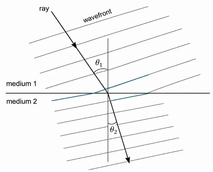
The diagram shows this idea using wavefronts. A wavefront represents points on the light wave that are moving together. The ray is drawn at right angles to the wavefronts, showing the direction in which the light travels. In medium 1, the wavefronts have one direction. After crossing into medium 2, the wavefronts turn to a new direction, and the ray turns with them.
This turning happens at the boundary because the speed change begins there. One edge of the incoming wavefront reaches medium 2 first and changes speed first. The other edge is still in medium 1 for a short time. Since the two edges do not move the same distance during that short interval, the wavefront rotates. Once the whole wavefront has entered medium 2, all parts of it again travel at the same speed, so it continues in a straight line in the new direction.
This is why refraction is not caused by the material “pulling” the ray sideways. The ray bends because the wavefront changes direction when different parts of it experience different speeds while crossing the boundary. After the beam has fully entered the second medium, there is no further bending unless it meets another boundary.
The angles θ1 and θ2 are measured from the normal, not from the surface. The normal is the line drawn at right angles to the boundary. If light enters a medium where it travels more slowly, the ray bends toward the normal. If it enters a medium where it travels faster, the ray bends away from the normal. The wavefront picture helps explain why this bending happens, while Snell’s Law gives the exact mathematical relationship between the two angles.
This diagram shows refraction using wavefronts: when light crosses from one medium into another, the ray changes direction at the boundary because the wavefront changes orientation.
This technical illustration explains refraction using the wavefront model. A light ray enters from medium 1, crosses the boundary, and continues into medium 2 with a changed direction. The wavefronts above and below the boundary show how the orientation of the wave changes as light enters the second medium. The normal is drawn at the point of incidence, and the angles θ₁ and θ₂ are measured from the normal. The diagram helps students connect the bending of a ray with the change in wavefront direction at the boundary between two media.
What Refraction Really Means
Refraction occurs when light crosses a boundary between two materials and changes speed. For example, light travels at different speeds in air, water, glass, plastic, diamond, and optical fibre. If a light ray enters the new material at an angle, one side of the wavefront slows down or speeds up before the other side. This causes the ray to change direction.
The ray does not bend because it is “pulled” by the material in a mechanical sense. It changes direction because the speed of light is different in the two media. The ray model gives us a simple way to represent this change: we draw the incoming ray, the boundary, the normal, and the refracted ray.
The normal is an imaginary line drawn perpendicular to the boundary at the point where the ray enters the new medium. Angles in refraction are always measured from the normal, not from the surface. This is one of the most important habits students need to develop when solving refraction problems.
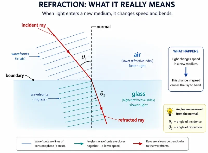
This diagram shows that refraction happens when light enters a new medium, changes speed, and bends, with all angles measured from the normal.
This educational illustration explains what refraction really means. A light ray travels from air into glass, crossing a boundary and bending toward the normal because light moves more slowly in glass than in air. The diagram shows the incident ray, the refracted ray, the boundary between the two media, the normal, and the angles of incidence and refraction. It also uses wavefronts to suggest that the change in direction happens because light changes speed in the new medium, helping students connect the ray model with the deeper physical idea behind refraction.
Key Terms in Refraction
Incident ray
The incoming ray that reaches the boundary between two materials.
Refracted ray
The ray that continues into the second material after changing direction.
Normal
An imaginary line drawn at 90° to the boundary at the point where the ray meets the surface.
Angle of incidence
The angle between the incident ray and the normal. It is commonly written as θ1.
Angle of refraction
The angle between the refracted ray and the normal. It is commonly written as θ2.
Medium
A material through which light travels, such as air, water, glass, or plastic.
Refractive index
A number that describes how much a material slows light compared with its speed in vacuum.
Refractive Index
The refractive index of a material tells us how much light slows down in that material. It is usually represented by n. A larger refractive index means light travels more slowly in that material.
The refractive index is defined as:
$$n = \frac{c}{v}$$
Here, c is the speed of light in vacuum and v is the speed of light in the material. Since light travels fastest in vacuum, the refractive index of ordinary transparent materials is greater than 1.
Medium
Approximate Refractive Index
Meaning
Air
1.00
Light travels almost as fast as it does in vacuum.
Water
1.33
Light slows down noticeably compared with air.
Glass
About 1.5
Light slows further, allowing lenses and prisms to bend rays strongly.
Diamond
About 2.42
Light slows greatly, producing strong refraction and brilliant internal reflections.
Snell’s Law
Snell’s Law describes how a light ray changes direction when it passes from one medium into another. It is written as:
$$n_1 \sin \theta_1 = n_2 \sin \theta_2$$
Here, n1 is the refractive index of the first medium, n2 is the refractive index of the second medium, θ1 is the angle of incidence, and θ2 is the angle of refraction. Both angles are measured from the normal.
Snell’s Law helps us calculate the refracted angle when light passes from air into glass, water into air, glass into air, or one transparent material into another. It is one of the central equations of geometrical optics because it turns a visual bending effect into a predictable relationship.
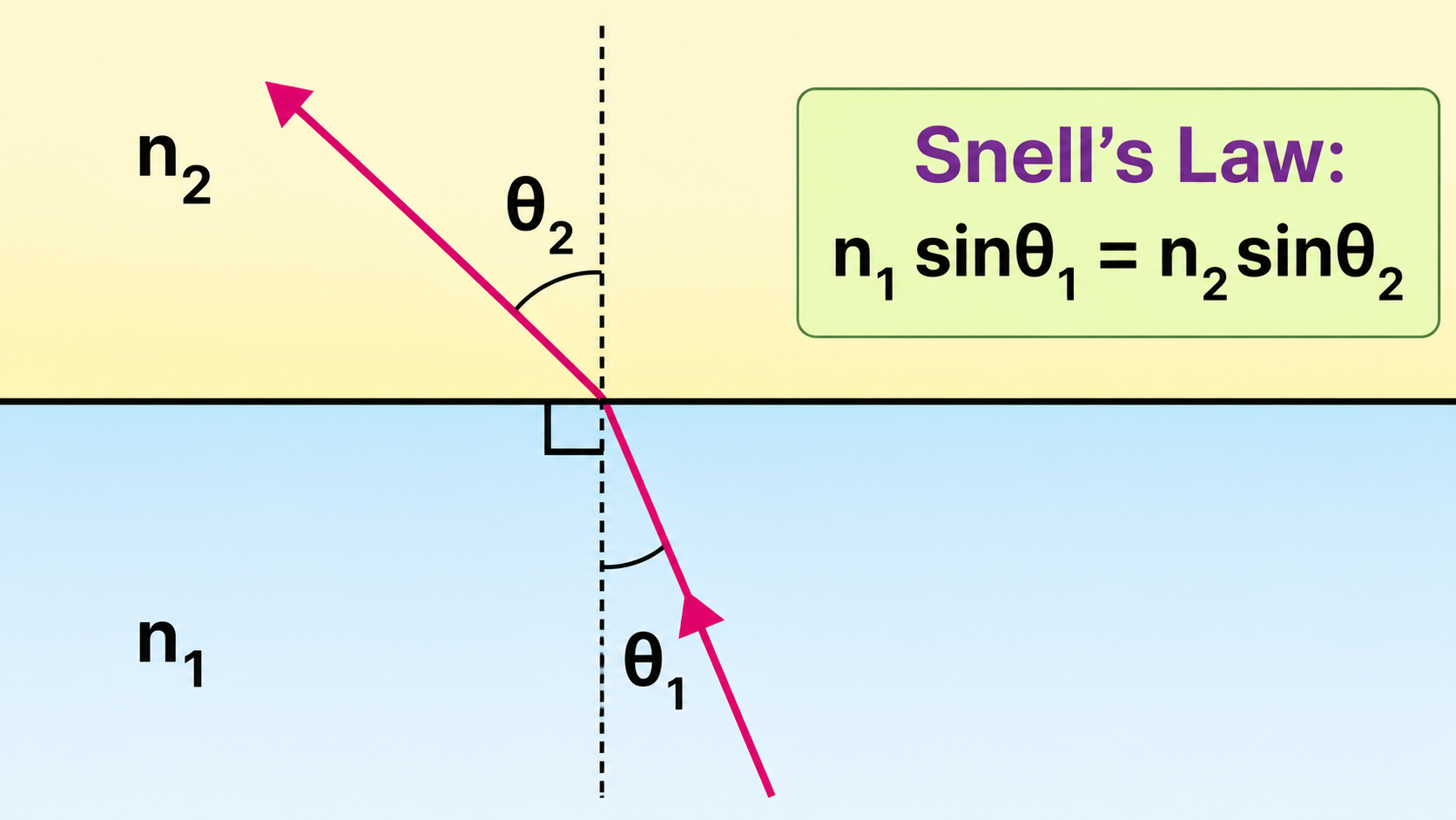
This diagram illustrates Snell’s Law by showing how a light ray changes direction at a boundary between two media with different refractive indices.
This educational diagram explains Snell’s Law using a simple ray-tracing view of refraction at a flat boundary. Two media are shown, labelled n1 and n2, separated by a horizontal boundary. A light ray crosses the boundary and bends as it passes from one medium into the other. A dashed vertical normal is drawn at the point of incidence, and the angles theta1 and theta2 are measured from this normal. A boxed equation shows Snell’s Law, n1 sin theta1 = n2 sin theta2, helping students connect the visual bending of the ray with the mathematical rule used to calculate the refracted angle.
Bending Toward and Away from the Normal
When light enters a medium with a higher refractive index, it slows down and bends toward the normal. For example, light travelling from air into glass bends toward the normal.
When light enters a medium with a lower refractive index, it speeds up and bends away from the normal. For example, light travelling from glass into air bends away from the normal.
Light Travels From
Light Travels Into
Speed Change
Direction Change
Lower n
Higher n
Slows down
Bends toward the normal
Higher n
Lower n
Speeds up
Bends away from the normal
Same n
Same n
No speed change
No bending at the boundary
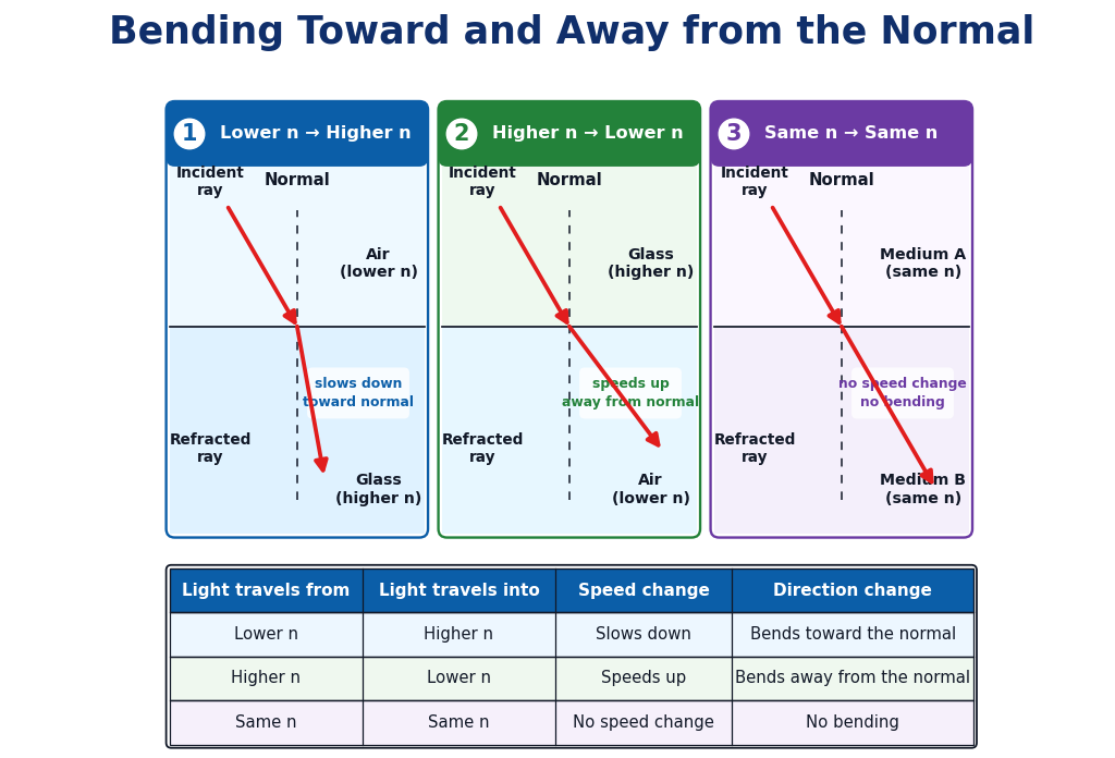
Light bends toward the normal when it slows down in a higher-index medium, bends away from the normal when it speeds up in a lower-index medium, and does not bend when the refractive index is unchanged.
This constructed educational diagram compares three basic refraction cases. In the first panel, light travels from a lower refractive index medium into a higher refractive index medium, slows down, and bends toward the normal. In the second panel, light travels from a higher refractive index medium into a lower refractive index medium, speeds up, and bends away from the normal. In the third panel, light passes between two media with the same refractive index and continues in a straight line without bending. The table below the panels summarises the speed and direction changes for each case.
Why the Normal Matters
A common mistake is to measure angles from the surface instead of from the normal. In reflection and refraction, the normal is the reference line. If the angle is measured from the surface, the calculation will usually be wrong.
The normal also helps students interpret the direction of bending. Saying “toward the normal” means the refracted ray has a smaller angle from the normal. Saying “away from the normal” means the refracted ray has a larger angle from the normal.
Quick Check: Toward or Away from the Normal?
1. Light travels from air into glass at an angle. Does it bend toward or away from the normal?
A. Toward the normal
B. Away from the normal
C. It must travel straight without bending
D. It reflects completely every time
Answer: A. Glass has a higher refractive index than air, so light slows down and bends toward the normal.
2. Light travels from glass into air at an angle. What happens to the refracted ray?
A. It bends toward the normal.
B. It bends away from the normal.
C. It stops at the boundary.
D. It becomes a sound wave.
Answer: B. Air has a lower refractive index than glass, so light speeds up and bends away from the normal.
3. From which line should angles of incidence and refraction be measured?
A. From the surface
B. From the normal
C. From the edge of the page
D. From the refractive index number
Answer: B. In refraction problems, both angles are measured from the normal, not from the surface.
Rigorous Technical Worked Examples
Worked Example 1: Air to Glass
Problem: A ray of light travels from air into glass. The refractive index of air is 1.00, and the refractive index of glass is 1.50. If the angle of incidence is 30°, find the angle of refraction.
Answer: The angle of refraction is approximately 19.5°. Because the light bundle passes into a denser material with a higher refractive index, the ray paths rotate closer toward the normal axis.
Worked Example 2: Water to Air
Problem: A ray of light travels from water into air. The refractive index of water is 1.33, and the refractive index of air is 1.00. If the angle of incidence in water is 30°, find the angle of refraction in air.
Answer: The angle of refraction resolves to approximately 41.7°. Moving out into a lower-index medium causes light velocity to rise, steering the ray path outwards away from the normal line.
Apparent Depth
Refraction explains why objects under water often appear closer to the surface than they really are. Light from the underwater object bends as it leaves the water and enters the air. The eye traces the incoming rays backward in straight lines, so the object appears to come from a shallower position.
This is why a swimming pool may look shallower than it is, and why a coin at the bottom of a cup may appear to shift position when water is added. The object has not moved. The path of light reaching the eye has changed.
This approximation is useful for simple reasoning, but more exact situations require careful ray tracing and Snell’s Law.
Total Internal Reflection
Total internal reflection occurs when light tries to travel from a higher-index medium into a lower-index medium at a sufficiently large angle. Instead of refracting out, all the light reflects back into the original medium.
This can happen only when light travels from a more optically dense medium to a less optically dense medium, such as from glass to air or from water to air. It cannot happen when light travels from air into glass.
The angle at which the refracted ray would just skim along the boundary is called the critical angle. At this point, the angle of refraction is 90°. The critical angle can be found from:
$$\sin \theta_c = \frac{n_2}{n_1}$$
This formula applies when n1 is greater than n2. If the angle of incidence is greater than the critical angle, total internal reflection occurs.
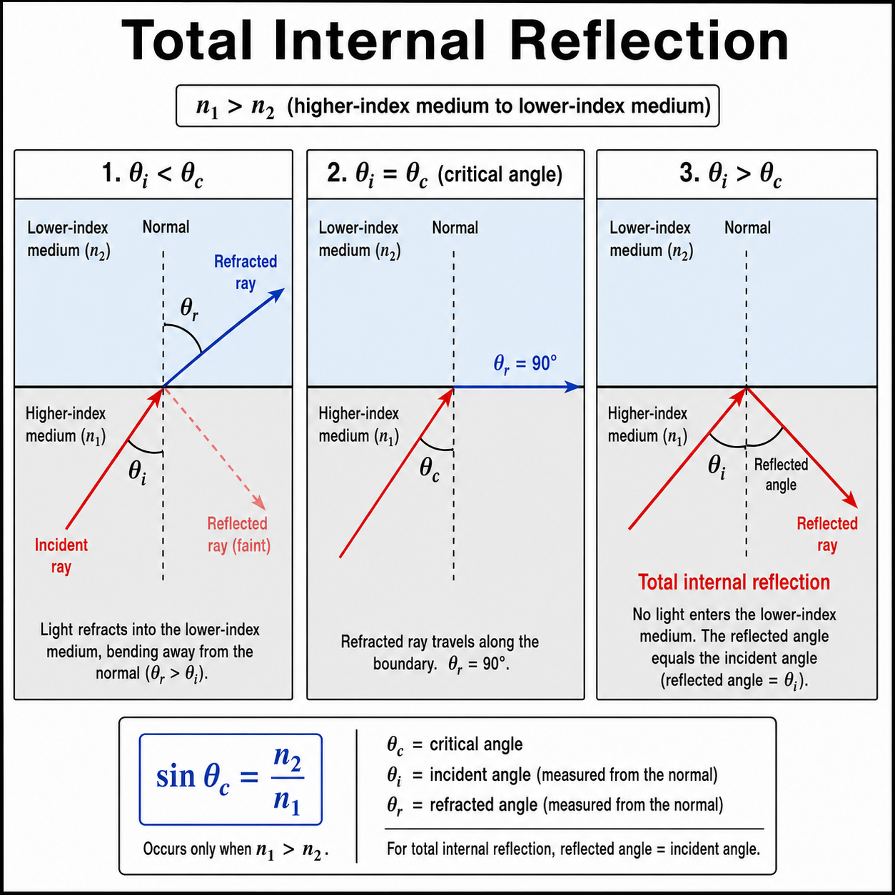
This diagram shows how light behaves at a boundary when it travels from a higher-index medium to a lower-index medium: ordinary refraction below the critical angle, a refracted ray along the boundary at the critical angle, and total internal reflection above the critical angle.
This technical illustration explains total internal reflection using three side-by-side cases for light travelling from a higher-index medium into a lower-index medium. In the first case, the angle of incidence is less than the critical angle, so part of the light refracts into the lower-index medium and bends away from the normal. In the second case, the angle of incidence equals the critical angle, so the refracted ray travels along the boundary and the angle of refraction is 90 degrees. In the third case, the angle of incidence is greater than the critical angle, so no refracted ray enters the lower-index medium and the light is totally internally reflected back into the original medium. The diagram also includes the critical-angle formula sin θc = n2 / n1 and notes that total internal reflection occurs only when n1 is greater than n2.
Why Total Internal Reflection Follows from Snell’s Law
Total internal reflection may look like a separate optical rule, but it is actually a direct consequence of Snell’s Law. Snell’s Law tells us what angle the refracted ray should have when light crosses from one medium into another:
$$n_1 \sin \theta_1 = n_2 \sin \theta_2$$
For total internal reflection to become possible, light must travel from a medium with a higher refractive index into a medium with a lower refractive index. In symbols, this means:
$$n_1 > n_2$$
This condition matters because the refracted ray bends away from the normal. As the angle of incidence θ1 increases, Snell’s Law requires the angle of refraction θ2 to increase even more. Eventually, the refracted ray reaches the limiting case where it travels exactly along the boundary between the two media.
At this limiting position, the angle of refraction is:
$$\theta_2 = 90^{\circ}$$
Substituting this into Snell’s Law gives:
$$n_1 \sin \theta_c = n_2 \sin 90^{\circ}$$
Since $\sin 90^{\circ} = 1$, this becomes:
$$n_1 \sin \theta_c = n_2$$
So the critical angle is found from:
$$\sin \theta_c = \frac{n_2}{n_1}$$
This equation shows why a critical angle exists only when n1 > n2. If n1 is greater than n2, then n2/n1 is less than 1, so a real value of θc can exist. But if light travels from a lower-index medium into a higher-index medium, then n2/n1 would be greater than 1, and no angle can have a sine greater than 1. In that case, total internal reflection cannot occur.
Now imagine increasing the angle of incidence beyond the critical angle. Snell’s Law would then require:
$$\sin \theta_2 > 1$$
But this is impossible, because the sine of an angle cannot be greater than 1. Therefore, no refracted ray can exist in the lower-index medium. Instead, the light is reflected completely back into the higher-index medium. This is total internal reflection.
In simple words, total internal reflection happens because Snell’s Law reaches a mathematical limit. Below the critical angle, refraction is possible. At the critical angle, the refracted ray travels along the boundary. Beyond the critical angle, Snell’s Law no longer allows a refracted ray, so the light remains inside the original medium by reflection.
Angle of Incidence
What Snell’s Law Predicts
What Happens Physically
θ1 < θc
A possible refracted angle less than 90°
Light refracts into the lower-index medium.
θ1 = θc
θ2 = 90°
The refracted ray travels along the boundary.
θ1 > θc
No possible refracted angle
Total internal reflection occurs.
Worked Example 3: Critical Angle
Problem: Light travels from glass into air. The refractive index of glass is 1.50 and the refractive index of air is 1.00. Find the critical angle.
Answer: The critical angle is approximately 41.8°. For any incident paths arriving at angles larger than this threshold value inside the glass, light undergoes total internal reflection.
Pause and Think: Total Internal Reflection
1. Why can total internal reflection happen from glass to air, but not from air to glass?
Total internal reflection requires light to travel from a higher refractive index to a lower refractive index. Glass has a higher refractive index than air, so glass-to-air can produce total internal reflection. Air-to-glass cannot, because the ray is entering a higher-index material instead.
2. If a glass-air critical angle is about 42°, what happens when the angle of incidence inside the glass is 50°?
Since 50° is greater than the critical angle, the ray undergoes total internal reflection. It does not refract out into the air.
3. Why is total internal reflection important in optical fibres?
Optical fibres guide light by repeated total internal reflection. This allows light signals to travel along thin fibres even when the fibre bends gently.
Refraction in Everyday Life
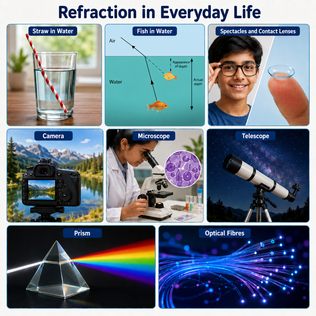
Refraction appears in many everyday situations. A straw in water appears bent because light from the underwater part changes direction as it leaves the water. Fish appear at different positions from where they really are because light bends at the water-air boundary. Spectacles correct vision by refracting light before it enters the eye.
Lenses in cameras, microscopes, telescopes, and projectors rely on refraction to bring rays together or spread them apart. Prisms use refraction and dispersion to separate white light into colours. Optical fibres use refraction and total internal reflection to transmit signals over long distances.
Spectacles and Contact Lenses
Corrective lenses adjust the path of incoming light so that the eye can focus images properly on the retina.
Cameras
Camera lenses refract light from a scene to form a real image on a sensor or film.
Microscopes
Microscope lenses use refraction to magnify tiny structures and make fine details visible.
Telescopes
Refracting telescopes use lenses to collect and focus light from distant objects.
Prisms
Prisms refract light and may separate white light into different colours because each wavelength bends by a different amount.
Optical Fibres
Optical fibres guide light by total internal reflection, allowing signals to travel through long, thin strands of glass or plastic.
Refraction appears in many familiar situations, from bent straws and apparent fish depth to spectacles, cameras, microscopes, telescopes, prisms, and optical fibres.
Refraction, Dispersion, and Colour
Refraction tells us that light bends when its speed changes. Dispersion adds another important idea: different colours of light may travel at slightly different speeds in the same material. Because of this, different colours may refract by slightly different amounts.
This is why a prism can spread white light into a spectrum. Violet light and red light do not bend by exactly the same amount. The same effect can also create chromatic aberration in lenses, where different colours focus at slightly different positions.
Refraction therefore connects directly to optical design. If a lens designer wants a sharp, colour-accurate image, it is not enough to know that light bends. The designer must also consider how different wavelengths bend.
Common Misconceptions About Refraction
Misconception 1: Refraction Happens Because Light Is Attracted to Glass or Water
Refraction is not caused by a pulling force in the ordinary mechanical sense. It happens because light travels at different speeds in different media, and this change in speed changes the direction of the ray when it crosses the boundary at an angle.
Misconception 2: Light Always Bends Toward the Normal
Light bends toward the normal only when it enters a medium with a higher refractive index. When it enters a lower-index medium, it bends away from the normal.
Misconception 3: Angles Are Measured from the Surface
In refraction problems, angles are measured from the normal, not from the boundary surface. Measuring from the surface gives the complementary angle and can lead to incorrect calculations.
Misconception 4: A Higher Refractive Index Means Light Travels Faster
A higher refractive index means light travels more slowly in that material. Since n = c / v, a smaller value of v gives a larger value of n.
Misconception 5: Total Internal Reflection Can Happen in Any Direction
Total internal reflection can occur only when light travels from a higher-index medium to a lower-index medium and the angle of incidence is greater than the critical angle.
Review Questions and Answers
1. What is refraction?
Answer: Refraction is the change in direction of light when it passes from one medium into another and changes speed.
2. What is the normal?
Answer: The normal is an imaginary line drawn perpendicular to the boundary at the point where the ray meets the surface.
3. From what line are angles of incidence and refraction measured?
Answer: They are measured from the normal reference axis line.
4. State Snell’s Law.
Answer: Snell’s Law is written as $n_1 \sin \theta_1 = n_2 \sin \theta_2$.
5. What happens when light enters a medium with a higher refractive index?
Answer: It decreases its travel velocity and bends toward the normal line.
6. What happens when light enters a medium with a lower refractive index?
Answer: It increases its travel velocity and bends away from the normal line.
7. What is refractive index?
Answer: Refractive index is a dimensionless value ratio ($n = c / v$) tracking how much a material slows light compared with its speed in vacuum.
8. What is total internal reflection?
Answer: Total internal reflection occurs when light travelling from a higher-index medium to a lower-index medium reflects completely back into the original medium because the angle of incidence is greater than the critical angle.
9. Why does a pool look shallower than it really is?
Answer: Light from the bottom of the pool bends outwards as it leaves water and enters air. The human eye traces the rays straight backward, causing the floor boundary to appear elevated.
10. Why are optical fibres connected to refraction?
Answer: Optical fibres guide light signals along curved tracks via repeated total internal reflection, which is a mathematical limiting condition of refraction logic.
Thought-Provoking Questions with Answers
1. Why is the ray model useful even though light is also a wave?
Answer: The ray model simplifies tracking light fields by treating straight paths as directional vectors. While it bypasses macro diffraction effects, it accurately predicts macro refraction, mirror reflection coordinates, and tracking geometry for complex instruments.
2. Why might refraction make objects appear displaced?
Answer: The brain operates on a straight-line light trace assumption. When refraction alters real vector angles at an interface, our visual center projects the rays back linearly, mapping an apparent virtual object position away from its true coordinate.
3. Why does Snell’s Law help connect observation with calculation?
Answer: Qualitative monitoring shows light path bending, but Snell’s Law provides structural predictability. It converts an observation into an analytical, solvable balance sheet matching material constants against geometric sine properties.
4. Why is total internal reflection useful rather than merely an unusual optical effect?
Answer: Traditional metallic mirror coatings suffer from minor structural absorption losses, but total internal reflection drops zero energy across its reflection transition. This flawless trap efficiency allows data signals to span long fiber lines with minimal dissipation.
5. Why must optical designers consider both refraction and dispersion?
Answer: Refraction dictates how an incoming ray changes its coordinates, but dispersion tracks the reality that separate colors experience distinct refraction curves. Designers must combine opposing material characteristics to achieve sharp color focus.
Comprehensive Numerical Problems with Answers
Problem 1: Light travels from air into water. The refractive index of air is 1.00, and the refractive index of water is 1.33. If the angle of incidence is 40°, find the angle of refraction.
Problem 4: The refractive index of water is approximately 1.33. Estimate the apparent depth of a coin at the bottom of water of real depth 24 cm, using the near-normal approximation.
Answer: The system critical angle boundary is approximately 48.8°.
Glossary
Apparent Depth
The visually perceived shallow coordinate height of a submerged object caused by refractive path bending at the air interface.
Critical Angle (θc)
The minimum incident parameter inside a denser medium that forces the outgoing refracted wavefront angle to track flat at 90°.
Dispersion
The physical property where distinct light wavelengths propagate through a medium at changing relative speeds, causing spectral color separation.
Medium
Any physical translucent or transparent substance through which light energy propagates, such as glass, gas, or water layers.
Normal
The fundamental structural baseline axis perpendicular (90°) to a material surface junction.
Refraction
The angular direction change experienced by a light wavefront when it steps across a multi-medium boundary and updates its phase speed.
Refractive Index (n)
A dimensionless material value parameter ($n = c / v$) measuring a medium’s capacity to slow down light wave propagation velocities.
Snell’s Law
The mathematical framework ($n_1 \sin \theta_1 = n_2 \sin \theta_2$) tracking the geometric correlation between incoming and outgoing angles across an interface.
Total Internal Reflection
A total reflecting trap transition occurring when light hits a less dense medium past the critical angle threshold, creating zero output leakage.
Refraction is the bending of light when it passes between materials and changes speed. The direction of bending depends on whether light enters a material with a higher or lower refractive index. Angles must always be measured from the normal, not from the surface.
Snell’s Law gives the mathematical rule for refraction: n1 $\sin \theta_1$ = n2 $\sin \theta_2$. It allows students to calculate refracted angles and understand how optical systems behave. Refraction also explains apparent depth, lenses, prisms, dispersion, and total internal reflection in optical fibres.
By studying refraction and Snell’s Law, students gain one of the central tools of geometrical optics. This tool supports later understanding of lenses, optical instruments, vision correction, fibre optics, and optical design.
Reflection Question
If refraction depends on how light changes speed in different materials, how might changing the material, shape, or angle of a transparent object allow us to design better lenses, prisms, fibres, and optical instruments?