Prepare for University Studies & Career Advancement

Mirrors and Image Formation

Mirrors are among the simplest optical devices, yet they reveal one of the most important ideas in geometrical optics: an image can be formed when light rays are redirected in a predictable way. A flat mirror forms a familiar virtual image, while curved mirrors can make light rays spread apart, come together, enlarge an image, shrink an image, or project a real image onto a screen.
This page extends the basic idea of reflection from plane mirrors to curved mirrors. It introduces plane, concave, and convex mirrors, explains how they form images, and shows why mirror shape matters in telescopes, vehicle mirrors, headlights, dental mirrors, solar concentrators, and many optical instruments.
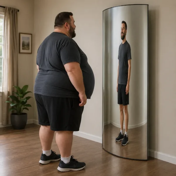
Artist impression of a larger-built person standing in front of a vertically curved mirror, with an upright virtual image that appears narrower while keeping roughly the same height.
A vertically curved mirror can distort the apparent width of an image while keeping it upright, helping students see how mirror shape affects image formation.

This artist impression shows a person standing in front of a mirror shaped like the surface of a vertical cylinder. The reflected image appears upright and about the same height, but noticeably narrower. The picture gives students an intuitive introduction to how curved mirrors can change image proportions, showing that image formation depends not only on reflection itself but also on the shape of the reflecting surface.

Geometrical Optics: Mirrors Within the Study of Light

Mirrors and image formation belong to geometrical optics because we can understand many mirror effects by drawing light rays. The ray model is not the whole story of light, but it is a powerful first model for understanding how images are formed by reflection.

Light and Optics

Connects mirror image formation to the wider study of light, including wave optics, lenses, lasers, fibres, photonics, and visual optics.

Geometrical Optics

Introduces the ray model of light and explains how reflection, refraction, lenses, mirrors, and optical instruments can be studied using geometry.

Refraction and Snell’s Law

Shows how light bends when it passes between different materials, forming the foundation for lenses, prisms, and optical fibres.

Mirrors and Image Formation

Extends reflection from flat mirrors to concave and convex mirrors used in imaging, safety, lighting, astronomy, and optical instruments.

Optical Instruments

Brings together mirrors, lenses, apertures, and image formation in cameras, microscopes, telescopes, projectors, and the human eye.

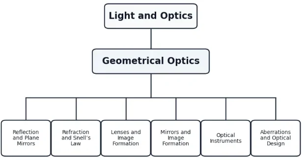
Simple 1-1-6 tree chart showing Light and Optics, Geometrical Optics, and six child topics: Reflection and Plane Mirrors, Refraction and Snell’s Law, Lenses and Image Formation, Mirrors and Image Formation, Optical Instruments, and Aberrations and Optical Design.
This 1-1-6 tree chart shows how Mirrors and Image Formation fits within the Geometrical Optics cluster.
This clean hierarchy chart presents Mirrors and Image Formation within the wider study of geometrical optics. Light and Optics appears as the top-level parent, Geometrical Optics appears as the middle-level topic, and six related subtopics branch from it: Reflection and Plane Mirrors, Refraction and Snell’s Law, Lenses and Image Formation, Mirrors and Image Formation, Optical Instruments, and Aberrations and Optical Design. The chart helps students see that mirrors are studied through the ray model of light alongside reflection, refraction, lenses, optical instruments, and optical design.

The Evolution of Mirror Design: History, Technical Hurdles, and Future Horizons

Catoptrics—the formal study of images formed by mirrors—represents one of humanity’s earliest endeavors to manipulate paths of light. The technology has scaled from reflective obsidian pools to complex giant telescope mirrors orbiting in space.

The Historical Journey

The earliest artificial mirrors were made of polished stones like volcanic obsidian, dating back to 6000 BCE in ancient Anatolia. Bronze and metal alloy mirrors emerged later in Egypt and Mesopotamia. The modern silvered-glass mirror was invented in 1835 by the German chemist Justus von Liebig, who developed a chemical deposition process that laid a microscopic film of metallic silver directly onto transparent glass.
In astronomy, early telescopes relied on glass lenses that suffered from severe chromatic distortion. In 1668, Sir Isaac Newton bypassed this limitation entirely by introducing the **Newtonian Reflector**, substituting the primary focusing lens with a curved metal mirror. Because reflection properties do not depend on light passing through a medium, mirrors allowed astronomers to observe deep space completely free of color fringing.

Contemporary Physics & Engineering Challenges

While spherical surfaces are the easiest to grind and polish mechanically, they do not bring parallel incoming light rays to a singular focus point. Outer border rays reflect more steeply than central rays, generating a blurry region known as **spherical aberration**.
To form flawless point images, mirrors must be configured into precise parabolic, hyperbolic, or elliptical cross-sections. Manufacturing these complex aspheric surfaces requires extreme mechanical precision, down to fractions of the wavelength of light. Furthermore, large glass mirrors deform under their own physical weight, creating structural distortions that degrade focus performance.

The Future: Liquid Mirrors and Segmented Adaptive Arrays

Modern mirror engineering is overcoming weight limitations through two bold concepts:
  • Adaptive Optic Segmented Mirrors: Instead of casting single massive glass monoliths, modern observatories use hundreds of smaller hexagonal segments actively managed by computational actuators. These actuators adjust the mirror’s profile thousands of times per second to neutralize atmospheric turbulence distortion instantly.
  • Liquid Mirror Telescopes (LMTs): By spinning a container of liquid mercury at a highly constant speed, centripetal force naturally shapes the liquid surface into a mathematically flawless, low-cost parabolic mirror. This technology provides incredibly crisp astronomical observations at a fraction of the cost of solid glass.

What Mirror Image Formation Really Is

Image formation by mirrors is not magic. It is geometry. Light from an object travels in many directions. Some of that light reaches a mirror, reflects according to the law of reflection, and then enters the eye or an optical instrument. The reflected rays either actually meet or appear to come from a common point. That point is interpreted as the location of the image.
When reflected rays really meet, the image is a real image. A real image can be formed on a screen because light actually passes through the image position. When reflected rays only appear to come from a point, the image is a virtual image. A virtual image cannot be caught on a screen because the rays do not actually meet there.

Real Image

A real image is formed when reflected rays actually meet. It can be projected onto a screen.

Virtual Image

A virtual image is formed when reflected rays appear to come from a point. It cannot be projected onto a screen.

Mirror Shape

The shape of the mirror determines how rays are redirected. A flat surface preserves ray spacing, a concave surface can converge rays, and a convex surface diverges rays.

The Law of Reflection Still Applies

All mirrors obey the law of reflection. The angle of incidence is equal to the angle of reflection:
$$\theta_i = \theta_r$$
For a plane mirror, the normal is easy to draw because the surface direction is the same everywhere. For a curved mirror, the normal changes from point to point. At any point on a spherical mirror, the normal is drawn along the radius toward the centre of curvature.
This is the key idea behind curved mirrors. The law of reflection has not changed, but the surface direction changes across the mirror. As a result, different parts of the mirror send reflected rays in different directions.

Types of Mirrors

Three mirror types are especially important in introductory geometrical optics: plane mirrors, concave mirrors, and convex mirrors.

Plane Mirror

A plane mirror is flat. It forms an upright virtual image that appears the same distance behind the mirror as the object is in front of it.

Concave Mirror

A concave mirror curves inward like the inside of a bowl. It can bring parallel rays together and may form real or virtual images depending on the object position.

Convex Mirror

A convex mirror curves outward like the outside of a ball. It spreads reflected rays apart and forms an upright, smaller virtual image.

Plane Mirrors

A plane mirror is the simplest mirror. It does not converge or diverge light rays in the way curved mirrors do. Instead, it redirects rays in an orderly way so that the image appears behind the mirror.
For a plane mirror:
  • The image is upright.
  • The image is virtual.
  • The image is the same size as the object.
  • The image appears the same distance behind the mirror as the object is in front of it.
  • The image is laterally inverted.
The object distance and image distance are related by:
$$d_i = d_o$$
The magnification is:
$$M = 1$$
This means a plane mirror does not enlarge or shrink the image. If the object is 1.5 m tall, the image also appears 1.5 m tall.
Artist impression of a short-haired lady standing in front of a full-length plane mirror, carrying a handbag on her right shoulder, with her upright reflected image shown in the mirror.
A plane mirror forms an upright image that appears behind the mirror, with the reflected figure matching the person’s posture, clothing, and shoulder bag.

This artist impression shows a short-haired lady standing in front of a full-length plane mirror while carrying a handbag on her right shoulder. Her reflected image appears upright and natural inside the mirror, but with the handbag on the left shoulder, helping students connect everyday mirror use with the idea of virtual image formation. The scene provides a simple visual example of how a plane mirror redirects light so that an image appears behind the mirror surface.

Concave Mirrors

A concave mirror is a converging mirror. Its reflecting surface curves inward. When parallel rays arrive near the principal axis, they reflect and pass through a point called the focal point.
Concave mirrors are useful because they can concentrate light. This is why they are used in reflecting telescopes, headlights, shaving mirrors, dental mirrors, solar furnaces, and some scientific instruments.

Key Points for a Concave Mirror

Centre of Curvature

The centre of curvature is the centre of the sphere of which the mirror surface is a part. It is usually labelled C.

Principal Axis

The principal axis is the straight line passing through the centre of the mirror and the centre of curvature.

Focal Point

The focal point is the point where rays parallel to the principal axis meet after reflection. It is usually labelled F.

Focal Length

The focal length is the distance from the mirror to the focal point. It is usually labelled f.

For a spherical mirror, paraxial geometry shows that the focal length is exactly half the radius of curvature:
$$f = \frac{R}{2}$$
Here, R is the radius of curvature and f is the focal length.

Convex Mirrors

A convex mirror is a diverging mirror. Its reflecting surface curves outward. Parallel rays reflect as if they came from a focal point behind the mirror.
A convex mirror always forms an image that is:
  • virtual,
  • upright,
  • smaller than the object,
  • formed behind the mirror.
Convex mirrors are useful when a wide field of view is more important than image size. This is why they are used in vehicle side mirrors, security mirrors, road safety mirrors, and shop surveillance mirrors.

The Mirror Equation and Magnification Engine

For spherical mirrors under the paraxial approximation, the geometric coordinates of object and image distance are governed by the mirror equation:
$$\frac{1}{f}=\frac{1}{d_o}+\frac{1}{d_i}$$
Here, f is the focal length, do is the object distance, and di is the image distance.
Linear magnification scales according to the following ratio:
$$M=\frac{h_i}{h_o}=-\frac{d_i}{d_o}$$
Here, M is magnification, hi is image height, and ho is object height. The explicit negative sign ensures that real images formed by reflection are properly mathematically flagged as inverted under standard Cartesian sign conventions.
Different textbooks may use slightly different sign conventions. The important idea is not to memorise signs blindly, but to connect the signs with the physical nature of the image: real or virtual, upright or inverted, enlarged or reduced.

Ray Diagrams for Concave Mirrors

Ray diagrams help students locate images without relying only on equations. For a concave mirror, three common rays are especially useful.

Parallel Ray

A ray travelling parallel to the principal axis reflects through the focal point.

Focal Ray

A ray travelling through the focal point reflects parallel to the principal axis.

Centre Ray

A ray travelling through the centre of curvature reflects back along the same path because it strikes the mirror normally.
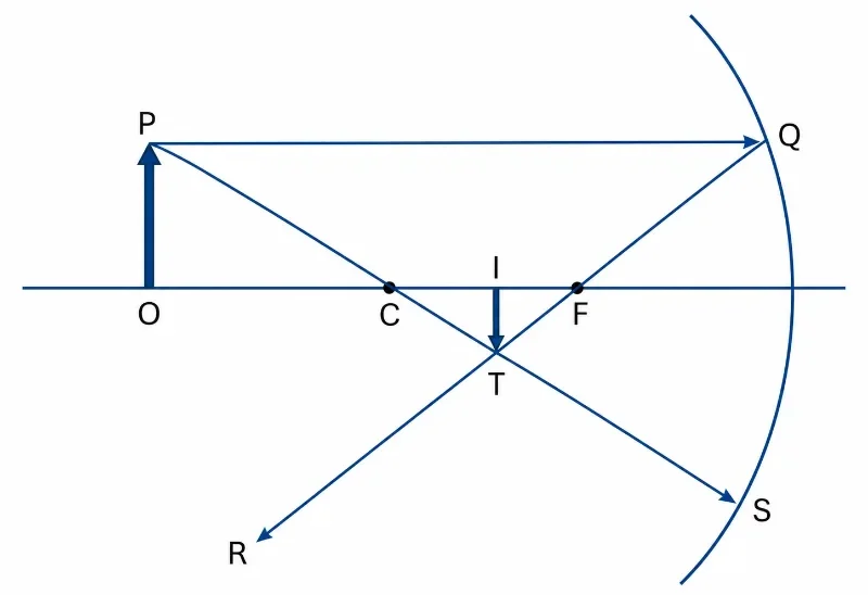
Where the reflected rays meet, a real image is formed. If the reflected rays spread apart, their backward extensions can be used to locate a virtual image.
Ray diagram showing an object before a concave mirror, with one ray parallel to the principal axis reflecting through the focal point and another ray through the centre of curvature reflecting back along the same path.
A concave mirror forms a real, inverted image when reflected rays from the top of the object meet below the principal axis.

This ray diagram shows how a concave mirror forms a real, inverted image. A ray from the top of the object travels parallel to the principal axis, strikes the mirror at Q, and reflects through the focal point F toward R. A second ray travels from P through the centre of curvature C to the mirror at S and reflects back along the same path. The reflected rays intersect at T, giving the top of the image, while I marks the image position on the principal axis.

Ray Diagrams for Convex Mirrors

For a convex mirror, reflected rays diverge. The focal point and centre of curvature are located behind the mirror. Because the rays do not really meet in front of the mirror, the image is found by extending the reflected rays backward.

Parallel Ray

A ray parallel to the principal axis reflects as if it came from the focal point behind the mirror.

Focal Direction Ray

A ray aimed toward the focal point behind the mirror reflects parallel to the principal axis.

Centre Direction Ray

A ray aimed toward the centre of curvature behind the mirror reflects back along the same path.
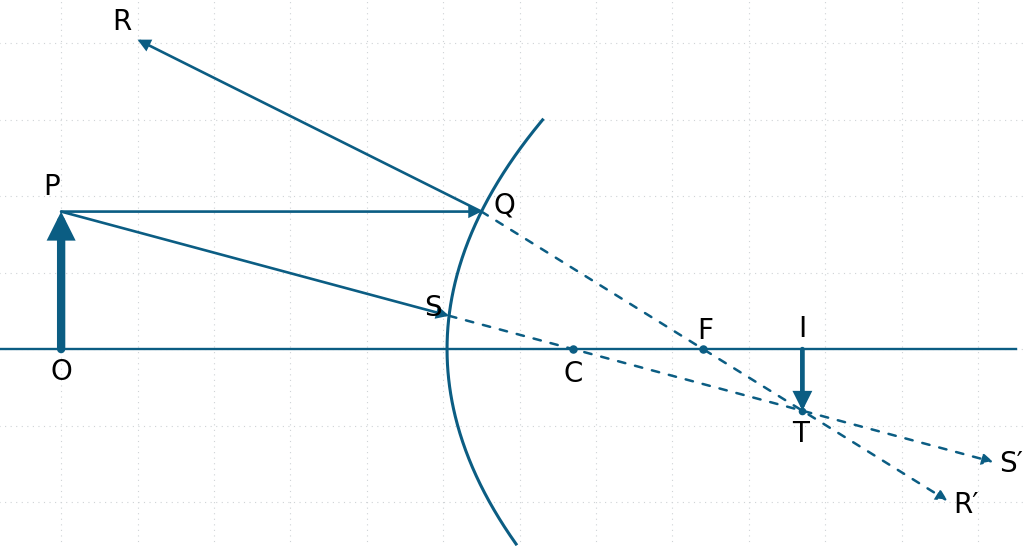
The image formed by a convex mirror is always virtual, upright, and reduced. This makes convex mirrors useful for seeing a wide area, but not for showing objects at their true size.
Ray diagram showing a convex mirror forming a virtual, upright, diminished image using reflected rays and dashed backward extensions.
A convex mirror forms a virtual, upright, diminished image where the backward extensions of the reflected rays meet behind the mirror.

This diagram shows image formation by a convex mirror. A ray from the top of the object travels parallel to the principal axis and reflects from Q as if it came from the focal point F behind the mirror. A second ray from P strikes the mirror at S, with its backward extension continuing along the straight line P–S–C–T–S′. The dashed extensions of the reflected rays meet at T, giving the top of the virtual image, while I marks the image position on the principal axis.

Image Formation by Object Position

For concave mirrors, the image depends strongly on where the object is placed relative to the focal point and centre of curvature.

Object Beyond the Centre of Curvature

The image is real, inverted, smaller than the object, and formed between the focal point and the centre of curvature.

Object at the Centre of Curvature

The image is real, inverted, the same size as the object, and formed at the centre of curvature.

Object Between Centre and Focus

The image is real, inverted, enlarged, and formed beyond the centre of curvature.

Object at the Focal Point

The reflected rays are parallel, so the image is formed very far away in the ideal ray model.

Object Between Focus and Mirror

The image is virtual, upright, enlarged, and formed behind the mirror.

Any Object in Front of a Convex Mirror

The image is virtual, upright, reduced, and formed behind the mirror.

Rigorous Technical Worked Examples

Worked Example 1: Image Distance for a Concave Mirror

Problem: A concave mirror has a focal length of 10 cm. An object is placed 30 cm in front of the mirror. Find the image distance.
Solution:
Use the thin mirror equation:
$$\frac{1}{f}=\frac{1}{d_o}+\frac{1}{d_i}$$
Substitute f = 10 cm and do = 30 cm:
$$\frac{1}{10}=\frac{1}{30}+\frac{1}{d_i}$$
$$\frac{1}{d_i}=\frac{1}{10}-\frac{1}{30} = \frac{3}{30}-\frac{1}{30}=\frac{2}{30}=\frac{1}{15}$$
$$d_i=15\text{ cm}$$
Answer: The image distance is 15 cm. The positive distance coordinate validates that it is a real image formed in front of the reflecting surface.

Worked Example 2: Magnification of a Mirror Image

Problem: An object is 4 cm tall and is placed 30 cm from a concave mirror. The image is formed 15 cm from the mirror. Find the magnification and the image height.
Solution:
Using the geometric magnification formula:
$$M=-\frac{d_i}{d_o}$$
$$M=-\frac{15}{30}=-0.5$$
Now link magnification to structural height:
$$M=\frac{h_i}{h_o} \Rightarrow -0.5=\frac{h_i}{4\text{ cm}}$$
$$h_i=-2\text{ cm}$$
Answer: The system magnification parameter evaluates to -0.5, yielding an image height coordinate of -2 cm. The mathematical negative prefix structurally confirms that the final image is inverted.

Worked Example 3: Radius of Curvature

Problem: A spherical mirror has a focal length of 12 cm. What is its radius of curvature?
Solution:
For a standard spherical boundary profile:
$$f=\frac{R}{2}$$
Rearranging the radius parameter gives:
$$R=2f$$
$$R=2 \times 12\text{ cm} = 24\text{ cm}$$
Answer: The mechanical radius of curvature evaluates to exactly 24 cm.

Everyday Applications of Mirrors

Mirrors are used wherever light must be redirected, concentrated, spread out, or used to form an image. The same basic reflection rules appear in simple household mirrors and advanced scientific instruments.

Bathroom and Dressing Mirrors

Plane mirrors form upright virtual images that help people inspect appearance, clothing, and movement.

Vehicle Mirrors

Convex mirrors give drivers a wider field of view, helping them see more of the road and nearby vehicles.

Dental Mirrors

Concave mirrors can produce enlarged upright images when used at close distances, helping dentists inspect small details.

Reflecting Telescopes

Large concave mirrors collect and focus faint light from distant astronomical objects.

Headlights and Torches

Curved reflectors help direct light into useful beams for illumination.

Security Mirrors

Convex mirrors allow shops, car parks, and corridors to be monitored over a wider angle.

Common Misconceptions About Mirrors

Mirror image formation is often introduced early in physics, but several misconceptions can remain hidden. Clearing them up helps students avoid confusion when they later study lenses and optical instruments.

Misconception 1: All Mirror Images Are Virtual

Plane mirrors and convex mirrors form virtual images, but concave mirrors can form real images when the object is placed outside the focal point.

Misconception 2: A Concave Mirror Always Magnifies

A concave mirror may magnify, reduce, or produce an image of the same size depending on where the object is placed.

Misconception 3: A Convex Mirror Shows True Size

A convex mirror gives a wider field of view but forms reduced images. This is why objects may appear smaller or farther away.

Misconception 4: The Focal Point Is a Physical Mark on the Mirror

The focal point is a geometric location where rays meet or appear to come from. It is not a physical dot on the mirror surface.

Misconception 5: Real Images Are More “Real” Than Virtual Images

Both real and virtual images can be seen. The difference is whether light rays actually meet at the image position.

Misconception 6: Mirror Equations Replace Ray Diagrams

Equations calculate image location and size, but ray diagrams explain the geometry and help students understand what the calculation means.
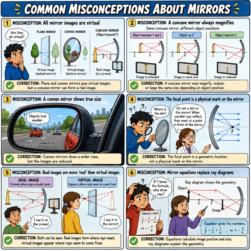
Educational comic explaining common misconceptions about mirror image formation, including real and virtual images, concave and convex mirrors, focal points, and ray diagrams.
Mirror image formation becomes clearer when students compare real and virtual images, concave and convex mirrors, focal points, and the role of ray diagrams.
This educational comic addresses six common misconceptions about mirrors. It explains that not all mirror images are virtual, since concave mirrors can form real images when the object is outside the focal point. It also shows that concave mirrors do not always magnify, convex mirrors provide a wider view while reducing image size, and the focal point is a geometric location rather than a physical mark on the mirror. The comic further clarifies that both real and virtual images can be seen, and that mirror equations should be used together with ray diagrams to understand image position, size, and geometry.

Connection to Other Optics Topics

Mirrors and image formation connect naturally to several other parts of optics. Reflection is the starting point, but the same idea of image formation appears in lenses, cameras, telescopes, the human eye, and optical design.

Optical Instruments

Shows how mirrors and lenses are combined in telescopes, microscopes, cameras, projectors, and other instruments.

Quick Check: Concepts and Calculations

1. A light ray strikes a concave mirror along a path that passes directly through its centre of curvature (C). What is the angle of reflection ($\theta_r$) for this ray?
A. $\theta_r = 90^{\circ}$
B. $\theta_r = 0^{\circ}$
C. $\theta_r = 45^{\circ}$
D. The ray scales based on the mirror power.


Answer: B. Any line drawn from the centre of curvature to a spherical surface is a normal line to that surface. Since the ray strikes along the normal, its angle of incidence is $0^{\circ}$, causing it to reflect directly back along its original path ($\theta_r = 0^{\circ}$).
2. An object is placed 10 cm in front of a convex mirror that has a focal length of -10 cm. Calculate the resulting image distance ($d_i$).
A. $d_i = -5\text{ cm}$
B. $d_i = -20\text{ cm}$
C. $d_i = +5\text{ cm}$
D. $d_i = \infty$


Answer: A. Applying the mirror equation:
$$\frac{1}{f} = \frac{1}{d_o} + \frac{1}{d_i} \Rightarrow \frac{1}{-10} = \frac{1}{10} + \frac{1}{d_i}$$
$$\frac{1}{d_i} = -\frac{1}{10} – \frac{1}{10} = -\frac{2}{10} = -\frac{1}{5} \Rightarrow d_i = -5\text{ cm}$$

Review Questions and Answers

1. What is a mirror?
Answer: A mirror is a highly polished reflecting surface that redirects light field fronts systematically to project an optical image map.
2. What is the difference between a real image and a virtual image?
Answer: A real image forms where reflected rays physically cross in front of the mirror plane. A virtual image forms where diverging rays only appear to cross when extended backward behind the mirror surface.
3. What type of image does a plane mirror form?
Answer: A plane mirror always projects an upright, virtual, laterally inverted image that matches the exact dimensions of the physical object.
4. What type of mirror can form a real image?
Answer: A concave mirror can project real images, provided the physical object is placed anywhere outside the primary focal point boundary.
5. What type of image does a convex mirror always form?
Answer: A convex mirror exclusively forms a virtual, upright, and diminished image behind its reflecting surface.
6. What is the focal point of a concave mirror?
Answer: It is the precise coordinate point along the optical axis where all parallel incoming light paths intersect after interacting with the mirror surface.
7. Why are convex mirrors used in vehicle side mirrors?
Answer: Their diverging nature compresses image representations, allowing a significantly wider field of view to be compressed onto the mirror area to reduce blind spots.
8. What is the relationship between focal length and radius of curvature for a spherical mirror?
Answer: Under the paraxial approximation, the focal length is exactly half of the physical radius of curvature: $f = R / 2$.
9. What does magnification tell us?
Answer: Magnification gauges the scale of the image relative to the object and dictates whether the image is upright (positive value) or inverted (negative value).
10. Why are ray diagrams useful?
Answer: They map out the literal spatial paths of photons, allowing students to geometrically trace image creation and verify calculated values visually.

Thought-Provoking Questions and Answers

1. Why can a concave mirror behave like a magnifying mirror at close range but form an inverted image when the object is farther away?
Answer: Within the focal distance, incoming rays reflect out in a diverging pattern, forcing the eye to track them back to an enlarged virtual point behind the mirror. Moving past the focal point shifts the geometry entirely, causing the mirror to converge the rays into a real inverted focus in front of the mirror.
2. Why is a convex mirror useful even though it makes images smaller?
Answer: The smaller image footprint is a deliberate engineering trade-off. Shrinking the image allows a vast panoramic landscape to be captured on a small surface area, which is vital for traffic safety and security monitoring.
3. Why do large telescopes often use mirrors instead of only lenses?
Answer: Large mirrors completely avoid chromatic aberration, can be structurally reinforced across their entire back surface to avoid physical sagging, and allow light paths to be folded down compact telescope structures.
4. Why should students not rely only on the mirror equation?
Answer: Formulas yield values but hide the physical mechanisms at play. Combining the equations with manual ray tracing helps students understand the geometry behind light paths.
5. Why does mirror shape have such a strong effect on image formation?
Answer: The mirror profile defines the slope of the surface normal at every coordinate. Since the angle of reflection is calculated relative to this shifting normal, changing the surface geometry reshapes the entire wavefront.

Comprehensive Numerical Problems with Solutions

Problem 1: A spherical mirror has a radius of curvature of 40 cm. Find its focal length.
Solution:
$$f=\frac{R}{2} \Rightarrow f=\frac{40\text{ cm}}{2}=20\text{ cm}$$
Answer: The focal length is 20 cm.
Problem 2: A concave mirror has a focal length of 15 cm. An object is placed 45 cm in front of the mirror. Find the image distance.
Solution:
$$\frac{1}{f}=\frac{1}{d_o}+\frac{1}{d_i} \Rightarrow \frac{1}{15}=\frac{1}{45}+\frac{1}{d_i}$$
$$\frac{1}{d_i}=\frac{1}{15}-\frac{1}{45} = \frac{3}{45}-\frac{1}{45}=\frac{2}{45}$$
$$d_i=22.5\text{ cm}$$
Answer: The image forms 22.5 cm in front of the mirror surface.
Problem 3: An object 6 cm tall forms an image with magnification -0.5. Find the image height.
Solution:
$$M=\frac{h_i}{h_o} \Rightarrow -0.5=\frac{h_i}{6\text{ cm}}$$
$$h_i=-3\text{ cm}$$
Answer: The image height evaluates to -3 cm, indicating an inverted orientation.
Problem 4: A convex mirror forms an image that is 2 cm tall from an object 8 cm tall. Find the magnification.
Solution:
$$M=\frac{h_i}{h_o} \Rightarrow M=\frac{2\text{ cm}}{8\text{ cm}}=0.25$$
Answer: The system magnification parameter is 0.25.
Problem 5: A concave mirror has a focal length of 20 cm. An object is placed at the centre of curvature. Where is the image formed?
Solution:
The center of curvature is located at:
$$d_o = R = 2f = 2 \times 20\text{ cm} = 40\text{ cm}$$
$$\frac{1}{20} = \frac{1}{40} + \frac{1}{d_i} \Rightarrow \frac{1}{d_i} = \frac{2}{40} – \frac{1}{40} = \frac{1}{40} \Rightarrow d_i = 40\text{ cm}$$
Answer: The image forms exactly at the centre of curvature, 40 cm away from the mirror.

Glossary

Concave Mirror

An inward-curving reflective surface that acts as a converging element for paraxial light fields.

Convex Mirror

An outward-curving reflective surface that acts as a diverging element for paraxial light fields.

Focal Length (f)

The linear metric tracking the distance between the mirror vertex and its principal focus plane.

Focal Point (F)

The axis coordinate where incoming parallel light fields converge or appear to expand outwards from after reflection.

Magnification (M)

The geometric scaling parameter comparing image height performance against object profile specifications.

Mirror

A boundary layer designed to interact with and redirect incident light wavefronts through reflection.

Plane Mirror

A completely flat mirror that preserves beam profiles to generate unmagnified, virtual, upright images.

Principal Axis

The baseline optical track vector crossing normal to the mirror center and through its center of curvature.

Real Image

An optical field map projected by the intersection of actual light rays in front of a mirror.

Virtual Image

An optical field map generated behind a mirror where diverging paths only appear to meet when projected backward.

External References

Summary

Mirrors form images by reflecting light. A plane mirror forms an upright virtual image of the same size as the object. A concave mirror can converge light and form real or virtual images depending on where the object is placed. A convex mirror spreads light apart and always forms an upright, reduced virtual image.
The same law of reflection applies to every mirror, but curved mirrors have changing surface directions. This changes the direction of the reflected rays and allows curved mirrors to form different kinds of images.
Mirror image formation is important because it connects simple ray diagrams to real optical devices. From bathroom mirrors to telescopes, from vehicle mirrors to dental tools, mirrors show how geometry can guide light and shape what we see.

Reflection Question

If a mirror can form an image without creating light of its own, what does that tell us about the difference between “seeing an object” and “seeing where light appears to come from”?
Last updated: 13 Jul 2026