
Electromagnetic induction is one of the great turning points in physics. It explains how a changing magnetic environment can produce an electric effect. When magnetic flux through a circuit changes, an electromotive force can be induced, and if the circuit is closed, an induced current may flow. This simple idea connects magnetism, electricity, motion, energy transfer, and many of the machines that power modern life.
Within electricity & magnetism, electromagnetic induction marks a shift from static fields to changing fields. In electrostatics, charges are often treated as still or slowly arranged. In magnetostatics, magnetic fields are studied mainly under steady conditions. Electromagnetic induction belongs to a more dynamic world, where motion, changing current, and changing magnetic flux can create new electrical effects.
The central idea is captured by Faraday’s Law: a changing magnetic flux induces an emf. This may happen when a magnet moves near a coil, when a coil rotates in a magnetic field, when the area or orientation of a circuit changes, or when current in one coil changes the magnetic field linked with another coil. Lenz’s Law then tells us the direction of the induced effect: the induced current or induced emf acts in a way that opposes the change that produced it. This is why induction is not only about producing electricity, but also about conserving energy.
Electromagnetic Induction Learning Pathway
Explore the core foundational sub-pages of this cluster path to trace how mechanical changes and varying source currents translate directly into physical vector fields and modern engineering hardware:
Magnetic Flux and Faraday’s Law
Quantifies how variations in magnetic line counts piercing a geometric area over time translate directly into a scalar induced electromotive force.
Lenz’s Law and Energy Conservation
The physical vector verification proving why induced field orientations must actively fight their source changes to prevent broken energy limits.
Self-Inductance and Mutual Inductance
Analyzes how time-dependent current updates generate self-reactive backing potentials inside single isolated loops or bleed across neighboring networks.
Generators, Motors, and Transformers
The ultimate engineering application block detailing how flux dynamics are harnessed to mechanical grids to convert, step-up, and distribute global power.
Electromagnetic induction also connects naturally with electrical circuits. Induced emf can drive current, oppose changing current, store energy in magnetic fields, and affect how circuits respond when switches open or close. This is why inductors, transformers, relays, motors, generators, wireless chargers, and power supplies all depend on induction in different ways.
At a deeper level, induction belongs to electrodynamics, the study of how electric and magnetic fields change and influence one another. It is closely linked to magnetic fields, because magnetic flux is the quantity that must change for electromagnetic induction to occur. Later, these ideas lead toward electromagnetic waves, where changing electric and magnetic fields support one another as energy travels through space.
The importance of induction is not limited to classroom coils and bar magnets. In power stations, generators convert mechanical motion into electrical energy. In the electrical grid, transformers raise and lower voltage for efficient transmission and safe use. In homes and vehicles, motors convert electrical energy into motion. In wireless charging, changing magnetic fields transfer energy without direct metal contact. In advanced fields such as superconductivity and magnetohydrodynamics (MHD), induction helps explain persistent currents, plasma behaviour, and magnetic field generation in large natural systems.
For students, electromagnetic induction is best understood as a story of change. A changing magnetic flux can create an electric response. A changing current can create a changing magnetic field. A changing field can transfer energy from one place to another. Once this idea becomes clear, generators, transformers, inductors, motors, and many modern electrical technologies become much easier to understand.
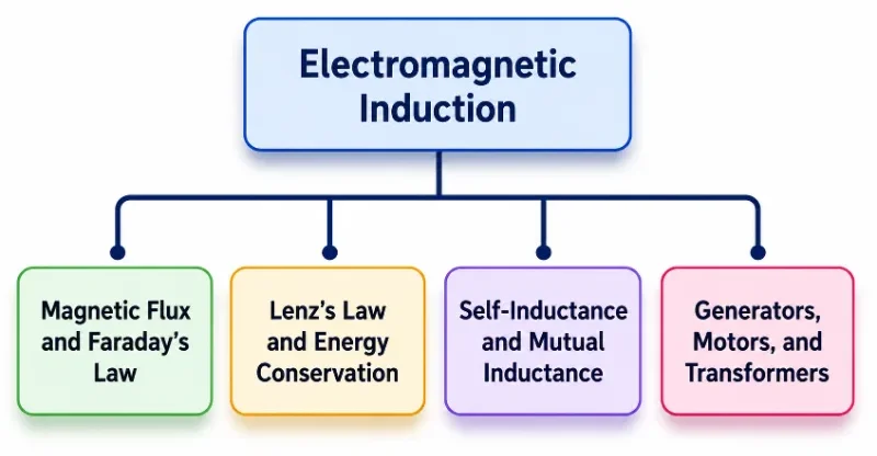
This simple tree chart shows the hierarchy of the Electromagnetic Induction cluster. The hub page sits at the top and connects to four subpages: Magnetic Flux and Faraday’s Law, Lenz’s Law and Energy Conservation, Self-Inductance and Mutual Inductance, and Generators, Motors, and Transformers. The picture helps students see the learning sequence from changing magnetic flux and induced emf to energy conservation, coil inductance, and practical electromagnetic devices.
Historical Background of Electromagnetic Induction
The story of electromagnetic induction begins in the early nineteenth century, when scientists were trying to understand whether electricity and magnetism were separate phenomena or different expressions of the same physical reality. The decisive breakthrough came from Michael Faraday, whose experiments in the 1830s showed that a changing magnetic situation could produce an electric current.
Faraday discovered that when a magnet is moved into or out of a coil of wire, a current can be produced in the coil. He also found that the effect depends on change. A stationary magnet near a stationary coil does not continuously generate current. The current appears only when the magnetic field linking the coil changes, such as when the magnet moves, the coil moves, or the magnetic field varies with time.
This was a profound discovery. It showed that electricity could be generated from motion and magnetism, providing the physical principle behind generators and much of the modern electrical age. Faraday’s experimental insight later became part of a larger theoretical structure when James Clerk Maxwell formulated Maxwell’s equations, which describe how electric and magnetic fields are connected in a unified electromagnetic theory.
Electromagnetic induction therefore stands at an important historical bridge. It connects laboratory observations with mathematical field theory, and it connects basic physics with real technologies such as power stations, transformers, motors, wireless charging systems, and sensors.
Theoretical Principles of Electromagnetic Induction
The two central principles of electromagnetic induction are Faraday’s Law and Lenz’s Law. Faraday’s Law tells us how much emf is induced when magnetic flux changes. Lenz’s Law tells us the direction of the induced emf or induced current.
Faraday’s Law of Induction
Magnetic flux describes how much magnetic field passes through a surface. For a uniform magnetic field passing through a flat area, magnetic flux can be written as:
\( \Phi_B = BA\cos\theta \)
\( \Phi_B \) is the magnetic flux, \( B \) is the magnetic field strength, \( A \) is the area, and \( \theta \) is the angle between the magnetic field and the normal to the surface.
Faraday’s Law states that an emf is induced when the magnetic flux through a circuit changes:
\( \varepsilon = -N\frac{\Delta \Phi_B}{\Delta t} \)
Here, \( \varepsilon \) is the induced emf, \( N \) is the number of turns in the coil, \( \Delta \Phi_B \) is the change in magnetic flux, and \( \Delta t \) is the time taken for the change. The larger the number of turns, or the faster the flux changes, the larger the induced emf.
In more advanced studies, Faraday’s Law may be written using calculus as:
\( \varepsilon = -N\frac{d\Phi_B}{dt} \)
This form expresses the same idea more precisely: the induced emf depends on the rate at which magnetic flux changes with time.
Lenz’s Law
Lenz’s Law gives the direction of the induced emf and induced current. It states that the induced current flows in a direction such that its own magnetic field opposes the change in magnetic flux that produced it.
This opposition is not a small detail. It is the reason electromagnetic induction respects energy conservation. If induced currents helped the original change instead of opposing it, energy could appear without work being done. Lenz’s Law prevents this by ensuring that induction always resists the change that causes it.
For example, if the magnetic flux through a coil is increasing, the induced current creates a magnetic field that opposes the increase. If the flux is decreasing, the induced current acts to maintain the original flux. This is why the negative sign appears in Faraday’s Law.
Mathematical Formulation
At school level, electromagnetic induction is usually introduced through flux, coil turns, and induced emf. At university level, the idea is expressed more generally through electric and magnetic fields.
A common integral form of Faraday’s Law is:
\( \oint_C \mathbf{E} \cdot d\mathbf{l} = -\frac{d}{dt}\int_S \mathbf{B} \cdot d\mathbf{A} \)
The left side represents the circulation of the electric field around a closed path. The right side represents the negative rate of change of magnetic flux through the surface bounded by that path.
This form shows a deeper idea: a changing magnetic field can create a circulating electric field. The induced electric field does not need a battery in the ordinary sense. It arises from the changing magnetic field itself. This concept becomes important in electrodynamics and later in the study of electromagnetic waves.
Vector Calculus Integration: The Differential Formulation of Faraday’s Law
While the integral form of Faraday’s Law successfully calculates the collective electromotive force generated around an extended physical loop, university-level electrodynamics requires a point-by-point spatial analysis. To understand how a changing magnetic field modifies space at an exact coordinate, we map the integral boundary law down to a localized point using Stokes’ Theorem. This foundational vector identity relates the line integral of a vector field around a closed loop path (\(C\)) directly to the flux of its curl across the bounded surface area (\(S\)):
$$ \oint_C \mathbf{E} \cdot d\mathbf{l} = \int_S (\nabla \times \mathbf{E}) \cdot d\mathbf{A} $$We substitute this surface integral into the integral formulation of Faraday’s Law:
$$ \int_S (\nabla \times \mathbf{E}) \cdot d\mathbf{A} = -\frac{d}{dt} \int_S \mathbf{B} \cdot d\mathbf{A} $$For a rigid, stationary surface boundary, the time derivative operator on the right side can move cleanly inside the integral as a partial derivative, altering only the temporal component:
$$ \int_S (\nabla \times \mathbf{E}) \cdot d\mathbf{A} = \int_S \left( -\frac{\partial \mathbf{B}}{\partial t} \right) \cdot d\mathbf{A} $$Because this mathematical equivalence holds true for any completely arbitrary surface geometry choice, the integrands themselves must be identical at every single position vector in space. This completes the transformation into the final differential form of Faraday’s Law, as organized inside Maxwell’s central field equations:
$$ \nabla \times \mathbf{E} = -\frac{\partial \mathbf{B}}{\partial t} $$This vector sentence states that a time-varying magnetic field density vector dynamically generates a curling, non-conservative electric field vector at that exact point in space, independent of whether a physical copper wire is present to receive it.
The Electromechanical Link: Lenz’s Law and Magnetic Braking Forces
Lenz’s Law is often introduced as a conceptual rule about arrow directions, but it has a real physical impact on moving machines. When a solid, non-magnetic conductive metal plate (such as copper or aluminum) swings through a highly localized magnetic field, the changing flux induces swirling loops of current—known as eddy currents—directly inside the bulk metal volume.
As these induced charges move with a local drift velocity through the metal lattice, they cut across the lines of the external magnetic field (\(\mathbf{B}\)). According to the Lorentz force expression, these moving currents experience a mechanical retarding force vector:
$$ \mathbf{F} = \int I(d\mathbf{l} \times \mathbf{B}) $$Lenz’s Law ensures that this resulting force vector points in the opposite direction of the plate’s physical velocity, creating a powerful mechanical drag known as Eddy Current Braking. The kinetic energy of the moving plate is converted into heat inside the metal through ohmic dissipation (\(I^2R\)). This kinetic-to-thermal transformation is used as a smooth, wear-free braking mechanism in high-speed trains, roller coasters, and industrial machinery.
AC Network Basics: Phase Behavior of Pure Inductors
The self-inductance behavior studied in transient switch-on events is also essential for understanding alternating current (AC) networks. When you drive a pure inductor with a time-varying sinusoidal current, \(i(t) = I_0 \sin(\omega t)\), the coil generates a continuous self-induced backing potential drop that opposes the current changes:
$$ v_L(t) = L\frac{di(t)}{dt} $$Substituting the time derivative of the current expression into this self-induction equation reveals the phase profile of the voltage drop:
$$ v_L(t) = L \frac{d}{dt}\left[ I_0 \sin(\omega t) \right] = \omega L I_0 \cos(\omega t) $$Using trigonometric identities, we rewrite this cosine expression back into a standard phase-shifted sine wave format:
$$ v_L(t) = \omega L I_0 \sin\left(\omega t + \frac{\pi}{2}\right) $$This mathematical derivation shows that the voltage wave across a pure inductor peaks earlier than the current wave. Specifically, the voltage leads the current by exactly \(90^\circ\) (\(\frac{\pi}{2}\) radians). This phase shift is a direct result of self-inductance and underpins the concept of inductive reactance (\(X_L = \omega L\)) explored in advanced AC network analysis.
Experimental Confirmation
Faraday’s original experiments used coils, magnets, iron rings, and galvanometers. When he moved a magnet near a coil, the galvanometer needle deflected, showing that a current had been induced. When the magnet stopped moving, the deflection disappeared. This showed that induction depends on changing magnetic flux, not simply the presence of a magnetic field.
Further experiments showed that the size of the induced emf depends on several factors: how quickly the magnetic flux changes, how many turns the coil has, how strong the magnetic field is, and how the coil is oriented relative to the field.
Heinrich Lenz later clarified the direction of the induced current. His work showed that the induced current always acts against the change that produces it. Together, Faraday’s Law and Lenz’s Law provide both the size and direction of induction effects.
Modern experiments use oscilloscopes, digital sensors, motion probes, and data loggers to measure induced emf more precisely. Yet the basic lesson remains the same as in Faraday’s original laboratory: changing magnetic flux produces electrical effects.
Practical Applications of Electromagnetic Induction
Electromagnetic induction is not only a theoretical idea. It is one of the main principles behind electrical energy production, transmission, conversion, and control.
Electric Generators
Generators convert mechanical energy into electrical energy. When a coil rotates in a magnetic field, or when magnetic flux through the coil changes, an emf is induced and electrical energy can be delivered to a circuit.Transformers
Transformers use mutual induction between coils to step AC voltage up or down. They are essential in power transmission because high voltage reduces energy losses over long distances.Induction Cooktops
Induction cooktops use rapidly changing magnetic fields to induce currents in suitable cookware. These induced currents produce heating inside the cookware itself, making the process fast and efficient.Wireless Charging
Wireless charging uses magnetic coupling between coils. A changing current in the charging pad produces changing magnetic flux, which induces voltage in a receiving coil inside the device.Sensors and Transducers
Many sensors use induction to detect motion, position, speed, or the presence of metal objects. Changes in magnetic flux or induced emf can be converted into useful measurement signals.Motors and Power Electronics
Induction effects appear in motor windings, switching circuits, power supplies, and energy conversion systems. They influence how current grows, decays, transfers energy, and produces motion.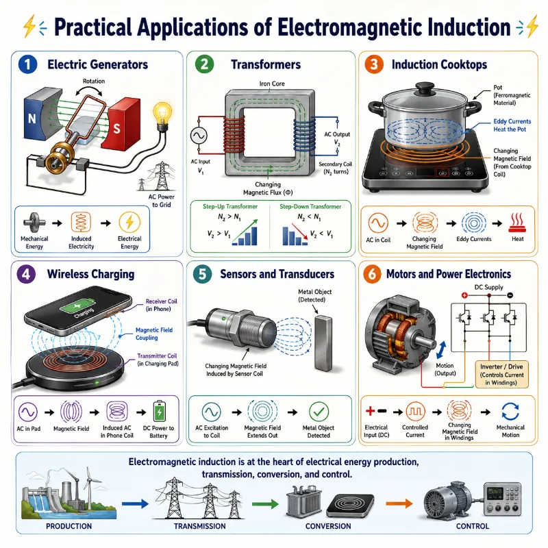
This illustration shows how electromagnetic induction appears in practical electrical systems. Electric generators convert mechanical motion into electrical energy, while transformers use mutual induction to step voltage up or down for efficient power transmission. Induction cooktops use changing magnetic fields to heat suitable cookware, and wireless chargers transfer energy through magnetic coupling between coils. Sensors and transducers use induction to detect motion, position, speed, or nearby metal objects. Motors and power electronics also depend on changing currents and magnetic fields to control energy flow and produce useful motion. The picture helps students see that electromagnetic induction is not only a classroom concept, but a working principle behind energy production, transmission, conversion, and control.
Advanced Topics and Future Directions
As science and engineering advance, electromagnetic induction continues to appear in new forms. The same basic idea of changing magnetic flux remains important, but the systems using it are becoming smaller, faster, smarter, and more efficient.
Energy Harvesting
Small induction-based devices can harvest energy from vibration, motion, or changing magnetic environments. Such systems may help power remote sensors and low-energy electronic devices.Renewable Energy Systems
Electromagnetic induction is central to wind, hydroelectric, and many other generator-based renewable energy systems. Improvements in generator and power-conversion design can make energy systems more efficient and reliable.Wireless Power Transfer
Wireless charging is expanding beyond phones into electric vehicles, medical devices, robotics, and industrial systems. These applications depend on controlled mutual induction and efficient magnetic coupling.Metamaterials and Magnetic Design
Engineered materials may help guide, concentrate, or shape electromagnetic fields in new ways. This could improve transformers, sensors, shielding systems, and wireless power devices.Superconducting Systems
In superconductivity, induced currents can persist with extremely low or zero resistance. This opens possibilities in magnetic levitation, powerful magnets, and advanced energy systems.From Classical Fields to Quantum Theory
At very small scales, electromagnetic interactions are studied through quantum electrodynamics. While school-level induction is classical, it belongs to the larger story of how fields, charges, light, and matter interact.Why Study Electromagnetic Induction?
Electromagnetic induction is worth studying because it explains how changing fields become useful electrical effects. It links basic physics to power generation, engineering design, modern electronics, and future energy systems.
Understanding Changing Fields
Electromagnetic induction helps students move beyond static pictures of electricity and magnetism. It shows how changing magnetic flux can produce induced emf and current.Explaining Power Generation
Most large-scale electricity generation depends on induction. Whether turbines are driven by steam, water, wind, or other sources, the generator principle depends on changing magnetic flux.Connecting Physics with Engineering
Induction appears in generators, transformers, motors, wireless chargers, sensors, power supplies, and electric vehicles. It is one of the clearest bridges between physics concepts and working machines.Building Mathematical Thinking
Students use equations involving magnetic flux, time rate of change, coil turns, current, voltage, and energy. This strengthens preparation for circuit analysis, electromagnetism, and engineering mathematics.Supporting Hands-On Learning
Experiments with coils, magnets, galvanometers, and oscilloscopes make invisible field effects visible. Students can see that current appears only when something changes.Preparing for Advanced Electrodynamics
Electromagnetic induction is one of the foundations of Maxwell’s equations, electromagnetic waves, AC circuits, field theory, and modern electrical technologies.Conclusion on Electromagnetic Induction
Electromagnetic induction is one of the most important ideas in classical physics. It shows that electricity and magnetism are not isolated topics, but deeply connected field phenomena. A changing magnetic flux can produce an electric effect, and this simple principle has transformed the way energy is generated, transmitted, converted, and used.
From Faraday’s early coil-and-magnet experiments to modern power grids, wireless charging systems, renewable energy generators, and precision sensors, electromagnetic induction continues to shape technology. It also prepares students for deeper study in circuits, electrodynamics, energy systems, and modern engineering.
The key lesson is simple but powerful: change matters. When magnetic flux changes, nature responds with induced emf. From that response comes much of the electrical world we depend on every day.
Numerical Examples on Electromagnetic Induction
Worked Numerical Examples
Example 1: EMF Induced in a Moving Conductor
Problem: A conductor of length \( 0.50 \ \text{m} \) moves perpendicular to a magnetic field of \( 0.20 \ \text{T} \) at a speed of \( 3.0 \ \text{m/s} \). Find the induced emf.
\( \varepsilon = Blv \)
\( \varepsilon = 0.20 \times 0.50 \times 3.0 \)
\( \varepsilon = 0.30 \ \text{V} \)
Answer: The induced emf is \( 0.30 \ \text{V} \).
Example 2: Faraday’s Law with a Coil
Problem: A coil with \( 200 \) turns experiences a change in magnetic flux from \( 0.010 \ \text{Wb} \) to \( 0.040 \ \text{Wb} \) in \( 0.20 \ \text{s} \). Find the magnitude of the induced emf.
\( |\varepsilon| = N\left|\frac{\Delta \Phi_B}{\Delta t}\right| \)
\( \Delta \Phi_B = 0.040 – 0.010 = 0.030 \ \text{Wb} \)
\( |\varepsilon| = 200 \times \frac{0.030}{0.20} \)
\( |\varepsilon| = 200 \times 0.15 = 30 \ \text{V} \)
Answer: The magnitude of the induced emf is \( 30 \ \text{V} \).
Example 3: Self-Inductance
Problem: A coil with self-inductance \( 2.0 \ \text{H} \) has its current increased by \( 5.0 \ \text{A} \) in \( 1.0 \ \text{s} \). Find the magnitude of the induced emf.
\( |\varepsilon_L| = L\left|\frac{\Delta I}{\Delta t}\right| \)
\( |\varepsilon_L| = 2.0 \times \frac{5.0}{1.0} \)
\( |\varepsilon_L| = 10 \ \text{V} \)
Answer: The magnitude of the induced emf is \( 10 \ \text{V} \).
Example 4: Transformer Voltage
Problem: A transformer has \( 500 \) turns on the primary coil and \( 100 \) turns on the secondary coil. If the primary voltage is \( 220 \ \text{V} \), find the secondary voltage.
\( \frac{V_s}{V_p} = \frac{N_s}{N_p} \)
\( V_s = V_p\frac{N_s}{N_p} \)
\( V_s = 220 \times \frac{100}{500} \)
\( V_s = 220 \times 0.20 = 44 \ \text{V} \)
Answer: The secondary voltage is \( 44 \ \text{V} \).
Example 5: Magnetic Flux Through a Loop
Problem: A loop of area \( 0.050 \ \text{m}^2 \) is placed in a magnetic field of \( 0.40 \ \text{T} \). The angle between the magnetic field and the normal to the loop is \( 30^\circ \). Find the magnetic flux.
\( \Phi_B = BA\cos\theta \)
\( \Phi_B = 0.40 \times 0.050 \times \cos 30^\circ \)
\( \Phi_B = 0.020 \times 0.866 \)
\( \Phi_B \approx 0.0173 \ \text{Wb} \)
Answer: The magnetic flux is approximately \( 0.0173 \ \text{Wb} \).
Multiple Choice Questions on Electromagnetic Induction
Quick Review MCQs
1. Who discovered electromagnetic induction?
A. James Clerk Maxwell
B. Michael Faraday
C. André-Marie Ampère
D. Heinrich Hertz
Answer: B. Michael Faraday discovered electromagnetic induction through experiments with magnets and coils.
2. Which law explains the direction of induced current?
A. Coulomb’s Law
B. Ohm’s Law
C. Lenz’s Law
D. Gauss’s Law
Answer: C. Lenz’s Law explains the direction of induced current by showing that it opposes the change that produces it.
3. What is the SI unit of magnetic flux?
A. Tesla
B. Weber
C. Henry
D. Volt
Answer: B. The SI unit of magnetic flux is the weber, symbol \( \text{Wb} \).
4. Which change increases the induced emf in a coil?
A. Reducing the rate of flux change
B. Increasing the rate of flux change
C. Keeping the magnetic flux constant
D. Removing the coil from the circuit
Answer: B. A faster change in magnetic flux produces a larger induced emf.
5. Which equation represents Faraday’s Law for a coil?
A. \( \varepsilon = IR \)
B. \( F = qvB \)
C. \( \varepsilon = -N\frac{\Delta \Phi_B}{\Delta t} \)
D. \( V = \frac{W}{q} \)
Answer: C. Faraday’s Law relates induced emf to the rate of change of magnetic flux through a coil.
6. A transformer works mainly by:
A. Mutual induction
B. Static electricity
C. Thermal expansion
D. Gravitational attraction
Answer: A. A transformer works by mutual induction between primary and secondary coils.
7. Which device converts mechanical energy into electrical energy using induction?
A. Electric motor
B. Electric generator
C. Capacitor
D. Resistor
Answer: B. An electric generator uses electromagnetic induction to convert mechanical energy into electrical energy.
8. Lenz’s Law is closely connected to which principle?
A. Conservation of energy
B. Conservation of mass only
C. Newton’s first law only
D. Boyle’s law
Answer: A. Lenz’s Law reflects conservation of energy because the induced effect opposes the change that produces it.
9. What happens to induced emf if magnetic flux remains constant?
A. It becomes very large
B. It becomes zero
C. It changes direction continuously
D. It doubles
Answer: B. If magnetic flux does not change, there is no induced emf due to Faraday’s Law.
10. In a coil, increasing the number of turns usually does what to the induced emf?
A. It reduces the induced emf to zero
B. It has no effect
C. It increases the induced emf for the same flux change per turn
D. It prevents induction from occurring
Answer: C. A coil with more turns has greater total flux linkage, so the induced emf is larger for the same rate of flux change per turn.
Common Misconceptions about Electromagnetic Induction
Electromagnetic induction can be confusing because the cause is often invisible. Students may see a coil, a magnet, or a circuit, but the real physical change is the changing magnetic flux through a surface. These misconceptions help clarify what induction is, and what it is not.
A Magnetic Field Alone Always Produces Current
A magnetic field by itself does not necessarily produce an induced current. Induction requires a change in magnetic flux. A stationary magnet near a stationary coil does not continuously generate current.Only Moving Magnets Can Cause Induction
Moving magnets are one way to change magnetic flux, but they are not the only way. Induction can also occur when a coil moves, rotates, changes area, changes orientation, or when current in another nearby coil changes.Lenz’s Law Is Only about Direction
Lenz’s Law does give the direction of induced current, but its deeper meaning is energy conservation. The induced effect opposes the change that produces it, so energy cannot appear without work being done.The Negative Sign Means the EMF Is Always Negative
The negative sign in Faraday’s Law is not simply a sign for numerical calculation. It represents opposition to change. In many school-level problems, students calculate the magnitude first and then discuss direction separately.Transformers Work with Steady DC
A transformer requires changing current to produce changing magnetic flux. Steady direct current may produce a brief induction effect when switched on or off, but it does not continuously induce voltage in the secondary coil.Induction Creates Energy from Nothing
Induction converts or transfers energy. In a generator, mechanical work is needed to rotate the coil or magnet. In a transformer, electrical energy is transferred from one circuit to another through changing magnetic flux.What Students Usually Get Wrong
Student Check: Avoiding Common Mistakes
1. A student says, “A stronger magnet always means a larger induced emf.” What is missing from this statement?
The statement misses the importance of change. A stronger magnet can help produce a larger emf, but only if the magnetic flux through the circuit changes. A strong stationary magnet near a stationary coil does not continuously induce emf.
2. A student calculates \( \varepsilon = -30 \ \text{V} \) and says the answer must be a physically negative voltage. What should be corrected?
The negative sign represents Lenz’s Law. It gives the direction of the induced emf relative to the chosen sign convention. For many introductory problems, the magnitude is written as \( 30 \ \text{V} \), while the direction is explained separately.
3. A student says that a transformer changes voltage because the two coils are electrically connected. What is wrong?
In a transformer, the primary and secondary coils are usually electrically separate. Energy is transferred by mutual induction through changing magnetic flux in the core.
4. A student says that Lenz’s Law makes induction weaker and therefore less useful. How should this be improved?
Lenz’s Law is not a flaw. It is a statement of energy conservation. The opposition means work must be done to produce electrical energy, which is exactly why generators convert mechanical energy into electrical energy instead of creating energy from nothing.
Bridge to University Thinking
At introductory level, electromagnetic induction is often introduced through magnets, coils, and changing flux. At university level, the same topic becomes part of field theory. Students learn that changing magnetic fields produce circulating electric fields, and that electric and magnetic fields are linked parts of one electromagnetic structure.
This deeper view leads naturally to Maxwell’s equations. Faraday’s Law becomes more than a rule for coils; it becomes a statement about space itself. A changing magnetic field can create an electric field even when there is no battery pushing charges around a wire.
This idea also prepares students for AC circuits, electromagnetic waves, motors, generators, transformers, antennas, power electronics, wireless energy transfer, and advanced topics in modern engineering. The coil-and-magnet experiment is simple, but the principle behind it reaches very far.
AC Network Basics: Phase Behavior of Pure Inductors
The self-inductance behavior studied in transient switch-on events is also essential for understanding alternating current (AC) networks. When you drive a pure inductor with a time-varying sinusoidal current, \(i(t) = I_0 \sin(\omega t)\), the coil generates a continuous self-induced backing potential drop that opposes the current changes:
$$ v_L(t) = L\frac{di(t)}{dt} $$Substituting the time derivative of the current expression into this self-induction equation reveals the phase profile of the voltage drop:
$$ v_L(t) = L \frac{d}{dt}\left[ I_0 \sin(\omega t) \right] = \omega L I_0 \cos(\omega t) $$Using trigonometric identities, we rewrite this cosine expression back into a standard phase-shifted sine wave format:
$$ v_L(t) = \omega L I_0 \sin\left(\omega t + \frac{\pi}{2}\right) $$This mathematical derivation shows that the voltage wave across a pure inductor peaks earlier than the current wave. Specifically, the voltage leads the current by exactly \(90^\circ\) (\(\frac{\pi}{2}\) radians). This phase shift is a direct result of self-inductance and underpins the concept of inductive reactance (\(X_L = \omega L\)) explored in advanced AC network analysis.
Reflection Questions
Think More Deeply
1. Why is change more important than strength in electromagnetic induction?
A strong magnetic field does not necessarily induce emf if it remains constant through the circuit. Induction depends on the rate of change of magnetic flux. A weaker field that changes quickly may induce a larger emf than a stronger field that does not change.
2. Why does electromagnetic induction show that electricity and magnetism are connected?
A changing magnetic field can produce an electric effect. This means magnetism can generate voltage and current under changing conditions. The connection is one of the central ideas that led to the unified theory of electromagnetism.
3. Why is electromagnetic induction central to modern power systems?
Most large-scale electricity generation uses induction. Generators convert mechanical motion into electrical energy, while transformers use induction to change voltage levels for efficient transmission and safer distribution.
Glossary
- Electromagnetic Induction
- The production of induced emf or current due to changing magnetic flux.
- Magnetic Flux
- A measure of how much magnetic field passes through a surface.
- Induced EMF
- The voltage produced when magnetic flux through a circuit changes.
- Faraday’s Law
- The law stating that induced emf depends on the rate of change of magnetic flux.
- Lenz’s Law
- The rule stating that the induced effect opposes the change that produces it.
- Flux Linkage
- The total magnetic flux linked with all turns of a coil, often written as \( N\Phi_B \).
- Self-Inductance
- The ability of a coil to induce emf in itself when its own current changes.
- Mutual Inductance
- The ability of one coil to induce emf in another coil through changing magnetic flux.
- Generator
- A device that converts mechanical energy into electrical energy using electromagnetic induction.
- Transformer
- A device that uses mutual induction to change AC voltage levels between two circuits.
Frequently Asked Questions about Electromagnetic Induction
FAQ
1. What is electromagnetic induction in simple terms?
Electromagnetic induction is the production of voltage or current when the magnetic flux through a circuit changes.
2. Does a magnetic field always induce current?
No. A magnetic field must change, or the flux through the circuit must change, for induction to occur.
3. What does Faraday’s Law tell us?
Faraday’s Law tells us that the induced emf depends on how quickly magnetic flux changes through a circuit.
4. What does Lenz’s Law tell us?
Lenz’s Law tells us that the induced current or emf acts in a direction that opposes the change that produced it.
5. Why is electromagnetic induction important?
It is important because it explains how generators, transformers, inductors, wireless chargers, motors, and many power systems work.
6. Why does a transformer need AC?
A transformer needs changing current to create changing magnetic flux. AC naturally provides this changing current, while steady DC does not continuously induce voltage.
7. Is electromagnetic induction only used in power stations?
No. It is also used in wireless charging, sensors, microphones, motors, power supplies, induction cooktops, electric vehicles, and many electronic systems.
8. What is the difference between self-inductance and mutual inductance?
Self-inductance happens when a changing current induces emf in the same circuit. Mutual inductance happens when changing current in one circuit induces emf in another magnetically linked circuit.