Prepare for University Studies & Career Advancement

Electrical Circuits

Electrical circuits are the branch of physics where electrical principles transition into functional networks. Instead of evaluating electrostatic charge, field vector lines, and potential thresholds strictly as isolated parameters, circuits demonstrate how these foundational mechanisms cooperate to channel energy, modulate currents, power loads, and process complex signal streams across modern technological systems.
A circuit is an engineered, continuous closed pathway optimized for directed charge migration and energetic transmission. An electromotive force or voltage source inputs potential energy per unit charge, moving current through the network, while interconnected passive components like resistors, capacitors, and inductors dynamically shape the system’s global impedance response. Consequently, circuit dynamics serve as the direct bridge linking elementary field theories to macro-scale applications such as telemetry networks, sensor arrays, industrial power grids, and digital microprocessors.
This hub establishes the analytical frameworks required to evaluate network behaviors before moving into complex node matrices. The core learning trajectory starts with current, resistance dynamics, and basic load profiles, where the linear relationships governing voltage gradients are defined. It then expands into composite network topologies, where the physical geometric arrangement of components dictates whether current remains uniform across a branch, divides into distinct parallel paths, or generates predictable step-down voltage drops.
When network architectures scale beyond basic series-parallel reductions, advanced loop rules become mandatory. More general matrix methods derive from fundamental physics invariants: the absolute conservation of electric charge at branching junctions and the absolute conservation of energy around closed loops. These governing principles allow for the simultaneous solution of multi-source, multi-branch network equations, making them indispensable for analyzing industrial-grade electrical systems.
This curriculum track also introduces time-dependent transient states and alternating-current steady states. You will analyze how energy storage elements accumulate and discharge charge configurations over time, where resistance and capacitance parameters together regulate the precise exponential rate of potential shifts. Alternating-current analysis then extends these models into time-varying sinusoidal regimes, where resistance, capacitive reactance, inductive reactance, driving frequency, and phase angle configurations dominate system behaviors.
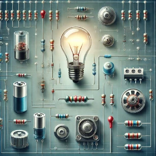
A conventional electrical circuit, including classic components like resistors, capacitors, inductors, a battery, a glowing light bulb, and a power grid representation.

Circuit Dynamics Through the Lens of Charge Conservation and Network Equilibrium

Electrical Circuits – Hub Overview

Establishes the complete network analysis framework, mapping charge migration and energy transfer rules across closed loops.

Current, Resistance, & Ohm’s Law

Defines charge drift velocity, material resistivity constraints, and the linear voltage-to-current proportionality limits.

Series & Parallel Circuits

Analyzes equivalent resistance reductions, current tracking, and node voltage dividers in multi-load grids.

Kirchhoff’s Laws & Network Analysis

Deploys Junction and Loop rules to build simultaneous linear matrix equations for complex multi-source systems.

RC Circuits & Transient Time Constants

Models the time-dependent exponential charging and discharging profiles of electrostatic storage components.

AC Circuits & Complex Impedance

Extends circuit mechanics into sinusoidal steady-states, evaluating frequency responses and phase vectors.

Electrical Circuits Learning Pathway

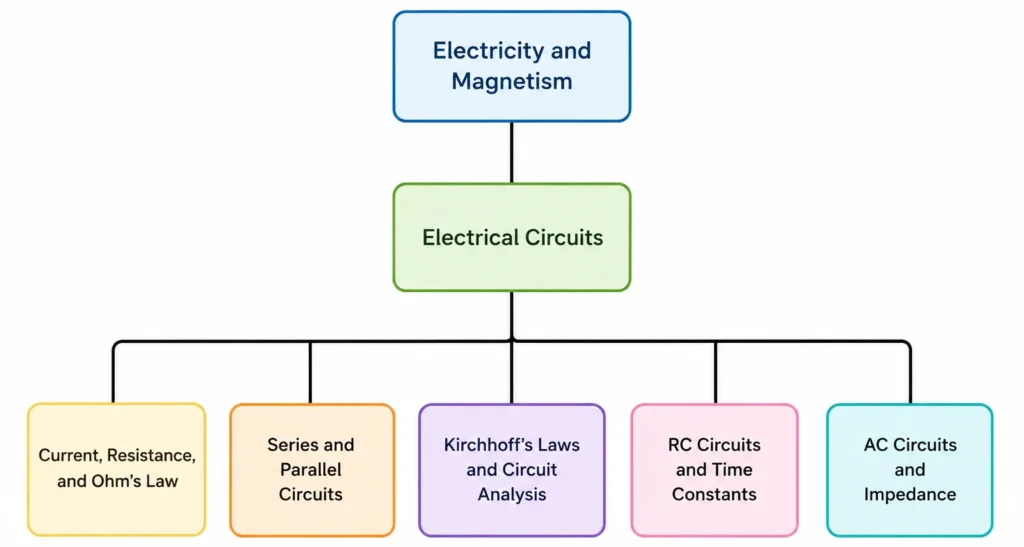
Simple hierarchy chart showing Electrical Circuits connected to Current, Resistance, and Ohm’s Law, Series and Parallel Circuits, Kirchhoff’s Laws and Circuit Analysis, RC Circuits and Time Constants, and AC Circuits and Impedance.
Electrical Circuits connects the study of current, resistance, circuit structure, circuit analysis, time-dependent behaviour, and AC impedance.
This simple tree chart shows Electrical Circuits as the parent topic for five connected learning pages: Current, Resistance, and Ohm’s Law; Series and Parallel Circuits; Kirchhoff’s Laws and Circuit Analysis; RC Circuits and Time Constants; and AC Circuits and Impedance. The chart helps students see the learning pathway clearly, beginning with basic current and resistance, then moving into circuit structure, loop and junction analysis, time-dependent capacitor behaviour, and alternating-current impedance.

Macroscopic Charge Transport and Drift Velocity Models

To evaluate electrical networks fundamentally, macro-scale lumped circuit properties must map back to microscopic charge carrier interactions inside an idealized conductor. While an applied potential difference creates a longitudinal electric field accelerating free charge carriers, frequent scattering mechanisms from localized material lattices establish a steady state average drift velocity vector, \(\mathbf{v}_d\). This transport behavior forms the basis for defining current density through the structural vector expression:
$$ \mathbf{J} = nq\mathbf{v}_d $$
Moving from micro-scale properties directly into macro-scale parameters allows the system to satisfy linear Ohm’s law transformations, mapping physical resistivity parameters across specific layout dimensions directly into a constant lumped resistance scalar value. For university preparation, establishing this deep link ensures that abstract circuit nodes are correctly understood as energy transformation boundaries governed by fundamental thermodynamics and conservation constraints.

The Drude Electron Scattering Model

Micro-to-Macro Parameter Invariants

In the absence of an external field, conduction electrons bounce randomly within a metal lattice at high thermal speeds, yielding zero net macroscopic charge transport. When a potential gradient introduces an electric field \(\mathbf{E}\), electrons experience a steady net directional force \(\mathbf{F} = q\mathbf{E}\). The relationship between this acceleration field and the resulting micro-scale drift response is derived through the average time between collisions \(\tau\):
$$ \mathbf{v}_d = \frac{q\tau}{m}\mathbf{E} $$
Where m is the electron mass and q is the elementary charge. Substituting this expression into the current density equation recovers the microscopic formulation of Ohm’s Law, \(\mathbf{J} = \sigma\mathbf{E}\), where conductivity \(\sigma\) is a pure material invariant property defined by \(\sigma = \frac{nq^2\tau}{m}\).

Geometrical Derivation of Lumped Resistance

To scale these vector field behaviors down into a practical scalar parameter that a page-builder or textbook schematic can track, microscopic conductivity must be integrated over a physical cylinder of cross-sectional area A and length L:
Physical VariableMicro-Field Vector FormMacro-Lumped Scalar Form
Charge Flux Rate\(\mathbf{J} = \sigma\mathbf{E}\)\(I = \int \mathbf{J} \cdot d\mathbf{A}\)
Potential Gradient\(\mathbf{E} = -\nabla V\)\(V = E \cdot L\)
Geometrical Scaling\(\rho = 1/\sigma\)\(R = \rho \frac{L}{A}\)
This rigorous reduction proves that macroscopic resistance R is not an arbitrary variable, but a direct geometric manifestation of structural lattice collision rates scaling across defined physical footprints.

Interactive Concepts Check & System Validation

Active Thought Experiment: Drastic Thermal Expansion

When the temperature of an ideal metallic conductor spikes significantly, how do the microscopic mean free time parameter \tau and the macroscopic lumped resistance value R adapt?

Show Microscopic Verification
Elevated thermal kinetic states cause the localized material lattice ions to vibrate with greater amplitude. This dramatic expansion of the effective scattering window cross-section increases the collision frequency, thereby forcing the mean free time between collisions (τ) to decrease.Because conductivity tracks proportionally with collision cycles (σ ∝ τ), a shrinking time step drops the global material conductivity, causing the macroscopic lumped resistance value (R) to rise linearly.

Core Analytical Frameworks: Network Modeling Foundations

The Hydrodynamic Analogy of Closed Networks

Visualizing Potential and Flow Invariants

To decouple intuitive misconceptions, university-level analysis leverages a rigorous fluid analogy. Electric potential or voltage drop maps directly to pressure differentials inside a closed piping system, where a battery behaves as a mechanical water pump raising the fluid’s potential height. Electric current matches the volumetric flow rate of water running through the conduit, while resistors act as restrictive bottlenecks that generate friction, creating a pressure drop across the restriction zone without consuming the fluid itself.

Macroscopic Network Energy Balance

Core Mechanism: Poynting Flux and Joule Dissipation

Energy in an active circuit is not technically pushed inside the volume of the copper wires; rather, it propagates through the electromagnetic field space surrounding the conductors, guided by the wire boundaries. The rate of total electrical work or power dissipation expression across a linear resistive element evaluates via:
$$ P = V \cdot I = I^2 R $$
Where V represents the electric potential drop across the component boundaries, I is the net charge current passing the boundary plane, and R tracks the material’s structural resistance value. This power manifests instantly as thermal energy, matching the fundamental conservation laws of the system.

Interactive Concepts Check & Network Intuition

Active Thought Experiment: Continuous Branch Flow

If electric current passes through a series network of three sequentially shrinking resistors, how does the magnitude of the current passing through the final, smallest resistor compare to the first?

Show System Verification
The electric current passing through all components arranged in a single series branch is exactly identical.According to the continuity principle and the conservation of charge, electric charge cannot accumulate or dissipate at any intermediate point inside a uniform wire branch. While the individual potential drops or localized voltage steps across each resistor vary based on their size, the total volume of charge passing a reference plane per unit time remains perfectly uniform throughout the branch.

Table of Contents

Core Components of Electrical Circuits

Electrical circuits are built from a small number of component types that work together to control current, voltage, energy transfer, timing, switching, and signal behaviour. Some components provide energy, some guide charge flow, some limit or store energy, and others control the direction or strength of electrical signals.

Power Sources

Batteries provide direct current by converting chemical energy into electrical energy. Generators convert mechanical energy into electrical energy, often producing alternating current. A power supply converts and regulates electrical energy so that devices receive a suitable voltage.

Conductors

Conductors such as copper and aluminium wires provide low-resistance paths for current. They connect components so that charge can move through a complete circuit.

Resistors

Resistors oppose current and transfer electrical energy, often as heat. They are used to limit current, divide voltage, protect components, and control circuit behaviour.

Capacitors

Capacitors store separated charge and energy in an electric field. They are used in timing circuits, filters, smoothing circuits, memory elements, and energy-storage applications.

Inductors

Inductors store energy in a magnetic field when current flows through a coil. They are important in filters, power supplies, motors, transformers, and AC circuit behaviour.

Switches

Switches control whether a circuit path is open or closed. A closed switch allows current to flow, while an open switch interrupts the circuit.

Diodes

Diodes allow current to flow more easily in one direction than the other. They are widely used in rectification, protection circuits, signal control, and electronic logic.

Transistors

Transistors act as electronic switches or amplifiers. They are fundamental to digital circuits, sensors, power control, computing, and communication systems.

Types of Electrical Circuits

Circuit behaviour depends strongly on how components are connected. The same components can produce different results if they are arranged in series, in parallel, or in a mixed network. Students should therefore learn to read circuit structure before applying formulas.

Series Circuits

In a series circuit, components are connected along one path. The same current flows through each component, while the supply voltage is divided among them. For resistors in series:

$$ R_{\text{total}} = R_1 + R_2 + R_3 + \cdots $$

Parallel Circuits

In a parallel circuit, components are connected across the same two points. Each branch has the same voltage, while the total current divides among the branches. For resistors in parallel:

$$ \frac{1}{R_{\text{total}}} = \frac{1}{R_1} + \frac{1}{R_2} + \frac{1}{R_3} + \cdots $$

Series-Parallel Circuits

Many real circuits combine series and parallel sections. These circuits are analysed step by step by identifying smaller groups of components and replacing them with equivalent resistances where possible.

Open Circuits

An open circuit contains a break in the path, so current cannot complete a loop. A switch in the OFF position creates an open circuit.

Short Circuits

A short circuit provides a very low-resistance path for current. This can cause excessive current, overheating, component damage, or safety hazards.

Fundamental Laws of Electrical Circuits

Circuit laws are not arbitrary rules. They express deeper physical principles such as conservation of charge, conservation of energy, and the relationship between voltage, current, resistance, and power.

Ohm’s Law

Relying on material properties under thermal equilibrium, Ohm’s law maps linear performance configurations via:

$$ V = IR $$

It tells us that current increases when voltage increases and decreases when resistance increases.

Kirchhoff’s Current Law (KCL)

Kirchhoff’s current law applies conservation of charge at an isolated junction node:

$$ \sum I_{\text{in}} = \sum I_{\text{out}} $$

The total current entering a node must equal the total current leaving it.

Kirchhoff’s Voltage Law (KVL)

Kirchhoff’s voltage law applies conservation of energy around a closed schematic loop:

$$ \sum V = 0 $$

Voltage rises and voltage drops around a complete loop must balance.

Power in Circuits

Electrical power measures the rate of work performance and thermodynamic energy transfer:

$$ P = VI = I^2R = \frac{V^2}{R} $$

Power helps explain heating, lighting, motor output, and energy consumption.

Advanced Network Simplification: Thevenin and Norton Invariants

When analyzing real-world circuit networks containing multiple active energy sources and mesh loops, calculating voltage drops across an isolated variable load using standard Kirchhoff systems becomes mathematically inefficient. Advanced network modeling relies instead on Thevenin’s and Norton’s Theorems, which state that any linear two-terminal circuit matrix can be reduced entirely to an equivalent single source paired with a single lumped internal impedance.

The Linear Equivalence Model

Dualities of Voltage and Current Source Reduction

Thevenin’s model provides a voltage-source perspective, matching an ideal open-circuit voltage source Vth connected in series alongside an equivalent internal network resistance Rth. Alternatively, Norton’s theorem provides a current-source duality, replacing the exact same complex multi-loop network with a single ideal short-circuit current source Ino wired in parallel with a Norton resistance. This structural symmetry is governed by the source transformation expression:

$$ V_{\text{th}} = I_{\text{no}} \cdot R_{\text{th}} $$

Where Rth equals the looking-in resistance measured across the target load terminals when all independent internal voltage sources are replaced with short circuits (zero potential drops) and all internal current sources are open-circuited (zero branch loops).

Maximum Power Transfer Condition

This network reduction directly unlocks the Maximum Power Transfer Theorem, which is a critical constraint inside audio amplification, telemetry processing, and radio transmission systems. To extract the absolute maximum potential power output from a fixed circuit network across an adjustable external load resistor RL, the load’s structural resistance must precisely match the network’s internal Thevenin source resistance:

$$ R_L = R_{\text{th}} $$

Under this matched condition, exactly half of the source energy is dissipated as internal heat within the network itself (I2Rth), while the remaining half is safely delivered to the functional application load, yielding an operational power transfer efficiency threshold of precisely 50%. Attempting to decrease or increase the load resistance away from this balance point causes a non-linear drop in the power transfer curve.

DC and AC Circuit Behaviour

Electrical circuits may operate with direct current or alternating current. The distinction is important because DC circuits often focus on steady values, while AC circuits require attention to frequency, reactance, impedance, and phase.

Direct Current Circuits

In a direct current circuit, current flows in one main direction. Batteries, solar cells, many electronic devices, sensors, and low-voltage control systems commonly use DC.

Alternating Current Circuits

In an alternating current circuit, voltage and current change direction periodically. Household and industrial power systems commonly use AC because it can be generated, transformed, and transmitted efficiently.

Time-Varying Voltage

A simple sinusoidal AC voltage may be written as:

$$ V(t) = V_0 \sin(2\pi ft) $$

Here, V_0 is the peak voltage and f is the driving frequency.

Reactance and Impedance in AC Circuits

In AC circuits, capacitors and inductors do more than simply oppose current. Their opposition depends on frequency and also affects the timing relationship between voltage and current. This is why AC circuits require the ideas of reactance and impedance.

Capacitive Reactance

A capacitor opposes alternating current through capacitive reactance:

$$ X_C = \frac{1}{2\pi fC} $$

As frequency increases, capacitive reactance decreases.

Inductive Reactance

An inductor opposes alternating current through inductive reactance:

$$ X_L = 2\pi fL $$

As frequency increases, inductive reactance increases.

Impedance

Impedance combines resistance and net reactance:

$$ Z = \sqrt{R^2 + (X_L – X_C)^2} $$

It describes the total opposition to alternating current and helps determine both current size and phase behaviour.

Applications of Electrical Circuits

Electrical circuits are used wherever energy, information, information tracking, control, measurement, or communication must be managed. Their importance reaches far beyond classroom diagrams.

1. Power Systems

Core Scope: Generation & Distribution Networks

Electrical circuits are used in generation, transmission, distribution, protection, and control of massive grid power networks.

2. Solid-State Electronics

Core Scope: Logic Processing & Signal Systems

Smartphones, microprocessors, biomedical monitors, and computer systems all depend on micro-scaled integrated circuit designs.

3. Automotive Systems

Core Scope: Powertrain Control & Energy Delivery

Modern consumer vehicles use dense electrical networks for powertrain management, array telemetry, vehicle charging loops, and sensor processing.

4. Industrial Automation & Robotics

Core Scope: Feedback Loops & Actuator Drives

Automated machines, industrial robotics, sensor feedback systems, and motor control drivers require circuit tracking frameworks.

5. Communication Architectures

Core Scope: Wave Modulation & Filtering

Broadcasting, satellite links, fibre-linked equipment, and mobile transceiver arrays rely on tuned frequency circuit nodes for filtering and signal amplification.

Worked Examples in Circuit Thinking

Numerical examples help students connect circuit diagrams with calculation. The aim is not only to substitute into formulas, but also to interpret what the result means physically.

Example 1: Series Resistance

Problem: Find the total resistance in a series circuit with R1 = 5 Ω, R2 = 10 Ω, and R3 = 15 Ω.
Solution:

$$ R_{\text{total}} = R_1 + R_2 + R_3 $$
$$ R_{\text{total}} = 5 + 10 + 15 = 30\ \Omega $$

Answer: The total lump sum series resistance evaluates to 30 Ω.

Example 2: Parallel Resistance Reduction

Problem: Find the total resistance in a parallel circuit configuration featuring branch assets R1 = 6 Ω, R2 = 3 Ω, and R3 = 2 Ω.
Solution:

$$ \frac{1}{R_{\text{total}}} = \frac{1}{6} + \frac{1}{3} + \frac{1}{2} $$
$$ \frac{1}{R_{\text{total}}} = \frac{1}{6} + \frac{2}{6} + \frac{3}{6} = \frac{6}{6} = 1\ \Omega^{-1} $$
$$ R_{\text{total}} = 1\ \Omega $$

Answer: The equivalent lumped parallel network resistance decreases to 1 Ω.

Example 3: Ohm’s Law

Problem: A 12 V battery source drives an isolated 4 Ω load resistor. Determine the branch current.
Solution:

$$ I = \frac{V}{R} = \frac{12}{4} = 3\ \text{A} $$

Answer: The steady state current evaluates to 3 A.

Example 4: Power Dissipation

Problem: Calculate the operational rate of thermal energy transfer produced by a 10 Ω resistor wire carrying a steady current value of 5 A.
Solution:

$$ P = I^2R $$
$$ P = 5^2 \times 10 = 25 \times 10 = 250\ \text{W} $$

Answer: The system transfers internal potential into thermal dissipation fields at a rate of 250 Watts.

Example 5: Capacitive Reactance Calculation

Problem: Find the capacitive reactance of a 100 μF storage element operating inside a steady AC frequency frame of 50 Hz.
Solution:

$$ X_C = \frac{1}{2\pi fC} $$
$$ X_C = \frac{1}{2\pi(50)(100 \times 10^{-6})} = \frac{1}{0.031416} \approx 31.83\ \Omega $$

Answer: The frequency dependent capacitive opposition evaluates to approximately 31.83 Ω.

Why Study Electrical Circuits?

Electrical circuits are worth studying because they make abstract electrical ideas visible, measurable, and useful. They show how energy moves, how devices are controlled, and how physical laws become working technology.

Understand Current Flow

Circuits help students understand how charge moves through components, how voltage drives current, and how resistance limits that flow.

Predict Component Behaviour

Students learn how resistors, capacitors, inductors, sources, switches, diodes, and transistors affect voltage, current, timing, and energy transfer.

Build Practical Skills

Circuit study supports hands-on work with multimeters, oscilloscopes, breadboards, power supplies, sensors, and electronic modules.

Use Analysis Tools

Ohm’s law, Kirchhoff’s laws, power formulas, equivalent resistance, and impedance give students structured methods for solving circuit problems.

Conclusion on Electrical Circuits

Electrical circuits form the working language of modern electrical and electronic systems. They connect physical ideas such as charge, voltage, current, resistance, capacitance, inductance, energy, and power to real technologies used in homes, vehicles, laboratories, industries, communication networks, and computing devices.
A strong understanding of circuits helps students see why components behave differently in series, parallel, DC, AC, steady-state, and time-varying conditions. Foundational principles such as Ohm’s law, Kirchhoff’s laws, power relationships, capacitor behaviour, and impedance provide the tools needed to analyse and design systems in energy, electronics, and communication systems.

Electrical Circuits — FAQ

What does the Electrical Circuits hub cover?
The Electrical Circuits hub introduces the main ideas needed to understand how circuits work: current, voltage, resistance, power, series and parallel connections, Kirchhoff’s laws, RC circuits, and AC impedance. It serves as a learning pathway from simple direct-current circuits to time-dependent and alternating-current behaviour.
What is an electrical circuit in simple terms?
An electrical circuit is a complete conducting path that allows electric charge to move. A simple circuit usually includes a voltage source, connecting wires, and one or more components such as resistors, switches, lamps, capacitors, or inductors. For steady current to flow, the circuit must form a closed loop.
What is the difference between current and voltage?
Current is the rate at which electric charge flows through a circuit. Voltage is the energy difference per unit charge between two points. A useful way to think about them is this: voltage provides the driving energy, while current describes how much charge is flowing each second.
What does resistance do in a circuit?
Resistance limits current flow. For a given voltage, a larger resistance produces a smaller current. Resistors are used to control current, divide voltage, protect components, transfer energy as heat, and shape how a circuit behaves.
What is Ohm’s law?
Ohm’s law relates voltage, current, and resistance:
$$ V = IR $$
It tells us that current increases when voltage increases and decreases when resistance increases, provided the component behaves ohmically. It is one of the first tools students use to analyse simple circuits.
What is the difference between series and parallel circuits?
In a series circuit, components are connected along one path, so the same current flows through every component. In a parallel circuit, components are connected across the same two points, so each branch has the same voltage while the total current divides among the branches.
Why are household circuits usually connected in parallel?
Household circuits are usually arranged in parallel so that each appliance receives the same supply voltage and can operate independently. If one device is switched off or fails, the other devices can still work because they are on separate branches.
What are Kirchhoff’s laws used for?
Kirchhoff’s laws are used to analyse circuits with branches and loops. Kirchhoff’s current law applies conservation of charge at junctions: total current entering equals total current leaving. Kirchhoff’s voltage law applies conservation of energy around loops: voltage rises and voltage drops must balance.
How is electrical power calculated?
Electrical power is the rate at which electrical energy is transferred or converted. It can be calculated using:
$$ P = VI $$
For mechanical or thermodynamic energy transfer across a linear resistor, it can also be evaluated using:
$$ P = I^2R $$
or alternatively:
$$ P = \frac{V^2}{R} $$
Power helps explain heating, lighting, motor output, energy use, and component power ratings.
What does a capacitor do in a circuit?
A capacitor stores separated charge and energy in an electric field. In an RC circuit, a capacitor does not charge or discharge instantly. Its voltage changes gradually, and the time constant \tau = RC controls how quickly the change happens.
What is the difference between DC and AC circuits?
In a direct-current circuit, current flows in one main direction. In an alternating-current circuit, voltage and current change direction periodically. AC circuits require extra ideas such as frequency, reactance, impedance, and phase difference.
What is impedance in AC circuits?
Impedance is the total opposition to alternating current. It includes ordinary resistance and frequency-dependent reactance from capacitors and inductors. Impedance affects both how much current flows and how voltage and current are timed relative to each other.
What are common mistakes students make when learning circuits?
Common mistakes include thinking current is “used up,” confusing voltage with current, mixing up series and parallel rules, applying Ohm’s law to non-ohmic devices without checking, and forgetting that voltage is measured across components while current is measured through components.
Why are electrical circuits important for university preparation?
Electrical circuits prepare students for physics, electrical engineering, electronics, computer engineering, robotics, control systems, power systems, and communication technologies. Circuit learning builds both mathematical skill and physical intuition because students must connect equations with real current paths, voltage changes, energy transfer, and component behaviour.

Review Questions and Answers

  1. What is an electrical circuit?
    Answer: An electrical circuit is a complete path that allows electric current to flow. A simple circuit usually includes a source of voltage, conducting wires, and components such as resistors, capacitors, lamps, switches, or other devices that control or use electrical energy.
  2. How are series and parallel circuits different?
    Answer: In a series circuit, components are connected along one path, so the same current flows through every component. In a parallel circuit, components are connected across separate branches, so the same voltage appears across each branch while the total current divides among the branches.
  3. What does Ohm’s law tell us?
    Answer: Ohm’s law relates voltage, current, and resistance:

    $$ V = IR $$

    It tells us that current increases when voltage increases and decreases when resistance increases, provided the component behaves ohmically.
  4. Why are Kirchhoff’s laws useful in circuit analysis?
    Answer: Kirchhoff’s laws help analyse circuits with several branches and loops. Kirchhoff’s current law says that current entering a junction must equal current leaving it. Kirchhoff’s voltage law says that voltage rises and voltage drops around a closed loop must balance.
  5. How does a resistor affect current flow?
    Answer: A resistor opposes the flow of current. For a fixed voltage, a larger resistance produces a smaller current. Resistors are also used to control current, divide voltage, protect components, and transfer electrical energy as heat.
  6. What does a capacitor do in a circuit?
    Answer: A capacitor stores separated charge and energy in an electric field. Capacitors are used in timing circuits, smoothing circuits, filters, flash units, and many electronic systems where voltage needs to change gradually.
  7. What does an inductor do in a circuit?
    Answer: An inductor stores energy in a magnetic field when current flows through it. It opposes sudden changes in current and is important in filters, motors, transformers, power supplies, and AC circuits.
  8. What is impedance in an AC circuit?
    Answer: Impedance is the total opposition to alternating current. It includes resistance and reactance, and it affects both the size of the current and the phase relationship between voltage and current.
  9. How are power and energy related in electrical circuits?
    Answer: Electrical power is the rate of energy transfer. It can be calculated using:

    $$ P = VI $$

    Electrical energy is power multiplied by time:

    $$ E = Pt $$

    These relationships help us understand heating, lighting, motor output, battery use, and energy consumption.
  10. Why are circuit diagrams important?
    Answer: Circuit diagrams use symbols to show how components are connected. They make circuits easier to analyse, build, test, troubleshoot, and explain.

Thought-Provoking Questions and Answers

  1. Why is it misleading to think of current as something that gets “used up”?
    Suggested answer: Current is the rate of charge flow. Charge moves around the circuit and is not normally consumed by components. What is transferred to components is energy, not charge. For example, a resistor receives electrical energy and converts it mainly into thermal energy.
  2. Why do real circuits often combine series and parallel sections?
    Suggested answer: Real circuits need to control voltage, current, resistance, timing, and reliability in different parts of the system. Series connections can divide voltage or limit current, while parallel branches allow components to operate independently or share the same voltage.
  3. Why are household appliances usually connected in parallel rather than series?
    Suggested answer: Parallel wiring allows each appliance to receive the same supply voltage and operate independently. If one appliance is switched off or fails, the others can still work.
  4. Why does circuit analysis become harder when there are many branches and loops?
    Suggested answer: In complex circuits, current can split and recombine in several places, and voltage changes can occur around several loops. Kirchhoff’s laws provide a systematic way to write equations for these junctions and loops.
  5. How do capacitors make circuits time-dependent?
    Suggested answer: A capacitor does not charge or discharge instantly. Its voltage changes gradually, and the rate of change depends on the resistance and capacitance in the circuit. This gives RC circuits their time-dependent behaviour.
  6. Why does AC circuit analysis require more than ordinary resistance?
    Suggested answer: In AC circuits, voltage and current change with time. Capacitors and inductors respond differently depending on frequency, producing reactance and phase shifts. Impedance is needed to describe this combined opposition to alternating current.
  7. How can simulation tools help students and engineers understand circuits?
    Suggested answer: Simulation tools allow circuits to be tested before they are built physically. They help predict voltage, current, timing, power, and signal behaviour under different conditions. This makes design faster, safer, and easier to refine.
  8. Why are circuit design skills important in renewable energy systems?
    Suggested answer: Renewable energy systems require circuits for power conversion, voltage regulation, battery charging, energy storage, monitoring, and grid connection. Good circuit design helps maintain efficiency, safety, and reliability when energy supply changes over time.
  9. How does miniaturisation affect modern circuit design?
    Suggested answer: Miniaturisation allows many circuit functions to fit into small devices such as phones, sensors, wearables, and medical equipment. However, it also creates challenges in heat management, power use, signal interference, and manufacturing precision.
  10. Why is electromagnetic interference important in circuit design?
    Suggested answer: Electromagnetic interference can disturb signals and cause circuits to behave unpredictably. Designers use shielding, grounding, filtering, and careful layout to reduce unwanted noise and improve reliability.
  11. What makes circuits for space, deep-sea, or industrial environments difficult to design?
    Suggested answer: Circuits in extreme environments may face radiation, heat, cold, pressure, vibration, corrosion, or limited access for repair. Designers must choose robust materials, add protection, and often include redundancy.
  12. What ethical issues are connected with the rapid growth of electronic circuits?
    Suggested answer: Circuit technology supports communication, medicine, education, and automation, but it also raises issues such as electronic waste, unequal access to technology, privacy, energy use, and dependence on digital systems. Responsible design must consider both performance and social impact.

Numerical Problems and Solutions

1. A resistor of 220 Ω is connected to a 9 V battery. Find the current.

Solution: Applying standard linear current parameters:

$$ I = \frac{V}{R} $$
$$ I = \frac{9}{220} \approx 0.0409\ \text{A} $$

Answer: The current is approximately 0.041 A, or 41 mA.

2. Two resistors, 100 Ω and 300 Ω, are connected in parallel. Find the equivalent resistance.

Solution: Solving parallel reciprocal constraint pathways:

$$ \frac{1}{R_{\text{eq}}} = \frac{1}{100} + \frac{1}{300} $$
$$ \frac{1}{R_{\text{eq}}} = \frac{3}{300} + \frac{1}{300} = \frac{4}{300}\ \Omega^{-1} $$
$$ R_{\text{eq}} = 75\ \Omega $$

Answer: The equivalent resistance is 75 Ω.
3. Three resistors, 50 Ω, 100 Ω, and 150 Ω, are connected in series with a 12 V source. Find the current.
Solution: Combining linear parameters constructively:

$$ R_{\text{eq}} = 50 + 100 + 150 = 300\ \Omega $$
$$ I = \frac{V}{R_{\text{eq}}} = \frac{12}{300} = 0.040\ \text{A} $$

Answer: The current is 0.040 A, or 40 mA.

4. A capacitor of 100 μF is connected to a 5 V source. Find the charge stored.

Solution: Evaluating electrostatic potential storage formulas:

$$ Q = CV $$
$$ Q = (100 \times 10^{-6})(5) $$
$$ Q = 500 \times 10^{-6}\ \text{C} = 5.0 \times 10^{-4}\ \text{C} $$

Answer: The stored charge is 5.0 × 10⁻⁴ C, or 500 μC.

5. An inductor of 0.5 H carries a current of 2.0 A. Find the stored energy.

Solution: Computing inductive core field energy loops:

$$ U = \frac{1}{2}LI^2 $$
$$ U = \frac{1}{2}(0.5)(2.0)^2 $$
$$ U = 1.0\ \text{J} $$

Answer: The stored energy is 1.0 J.

6. In a purely resistive AC circuit, VRMS = 120 V and R = 240 Ω. Find IRMS.

Solution: Calculating the Root-Mean-Square value transforms:

$$ I_{\text{RMS}} = \frac{V_{\text{RMS}}}{R} $$
$$ I_{\text{RMS}} = \frac{120}{240} = 0.50\ \text{A} $$

Answer: The RMS current is 0.50 A.

7. A transformer has primary turns Np = 1000, secondary turns Ns = 250, and primary voltage Vp = 240 V. Find the secondary voltage Vs.

Solution: Applying core turn ratio transformations:

$$ V_s = V_p \frac{N_s}{N_p} $$
$$ V_s = 240 \times \frac{250}{1000} = 60\ \text{V} $$

Answer: The secondary voltage is 60 V.

8. In a parallel circuit, resistors of 150 Ω and 300 Ω are connected across a 12 V source. Find the current in each branch.

Solution: Solving individual independent branch nodes:

$$ I_1 = \frac{12}{150} = 0.080\ \text{A} $$
$$ I_2 = \frac{12}{300} = 0.040\ \text{A} $$

Answer: The branch currents are 0.080 A and 0.040 A.

9. A bulb is rated 60 W at 120 V. Find its resistance.

Solution: Transforming the electric power dissipation expression:

$$ R = \frac{V^2}{P} $$
$$ R = \frac{120^2}{60} = \frac{14400}{60} = 240\ \Omega $$

Answer: The resistance of the bulb is 240 Ω.

10. A 10 Ω resistor is in series with a parallel combination of 20 Ω and 30 Ω. Find the total resistance.

Solution: First calculate the equivalent resistance profile of the isolated parallel sub-network:

$$ \frac{1}{R_p} = \frac{1}{20} + \frac{1}{30} $$
$$ \frac{1}{R_p} = \frac{3}{60} + \frac{2}{60} = \frac{5}{60}\ \Omega^{-1} $$
$$ R_p = 12\ \Omega $$

Now add the remaining linear series component resistor value constructively:

$$ R_{\text{total}} = 10 + 12 = 22\ \Omega $$

Answer: The total network resistance evaluates to 22 Ω.
Last updated: 07 Jul 2026