
Generators, motors, and transformers are three of the most important machines built from electricity and magnetism. They may look different in real life, but they all depend on the interaction between magnetic fields, electric currents, motion, and energy transfer.
A generator converts mechanical motion into electrical energy. A motor converts electrical energy into mechanical motion. A transformer changes alternating voltage and current levels using changing magnetic flux between coils. Together, these devices explain how power stations generate electricity, how machines produce motion, and how electrical energy is transmitted across long distances.
This topic brings together many earlier ideas: magnetic force on current-carrying wires, magnetic flux, Faraday’s law, Lenz’s law, self-inductance, and mutual inductance. Instead of treating these laws as separate formulas, this page shows how they appear inside real devices.
For students, this topic is important because it reveals how invisible fields become useful work. A spinning coil can light a city. A current in a wire can turn a motor. A changing magnetic field can raise or lower voltage without direct electrical contact between circuits. Generators, motors, and transformers are not merely devices; they are organised ways of controlling energy.
Quick Answer: How Are Generators, Motors, and Transformers Connected?
Generators, motors, and transformers are connected by the same electromagnetic principles, but they arrange energy flow in different ways. A generator uses changing magnetic flux to convert motion into electrical energy. A motor uses magnetic force on current-carrying conductors to convert electrical energy into motion. A transformer uses changing magnetic flux between coils to change AC voltage levels.
The shared idea is that magnetic fields provide a bridge between circuits, motion, and energy transfer. Faraday’s law explains induced emf, magnetic force explains motor action, and mutual induction explains transformer action.
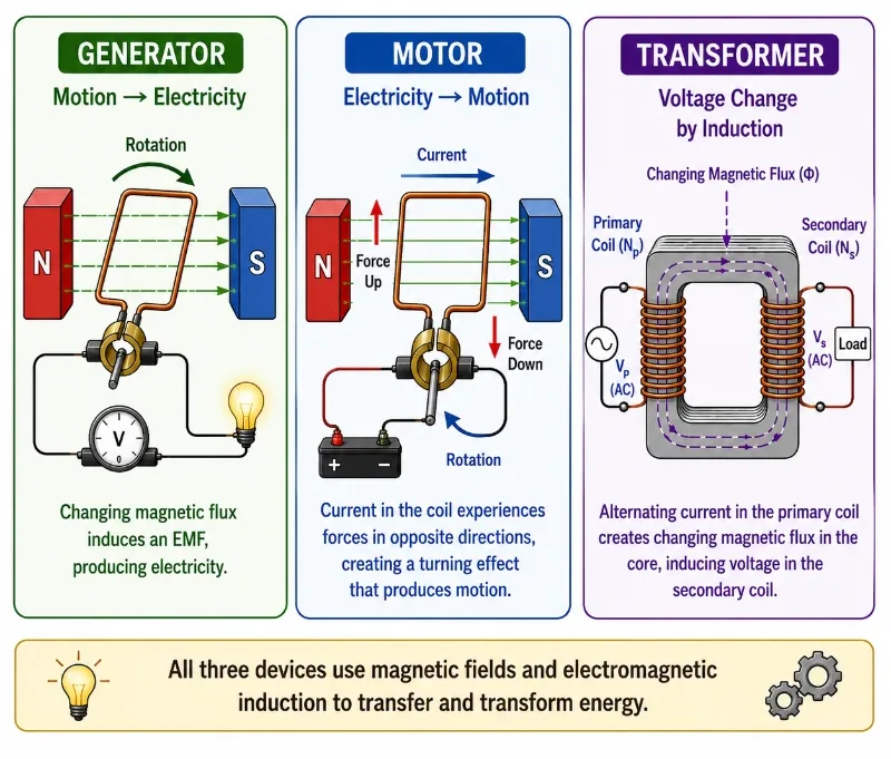
This overview diagram compares three important electromagnetic devices. A generator converts mechanical motion into electrical energy by changing magnetic flux. A motor converts electrical energy into mechanical motion using magnetic forces on a current-carrying coil. A transformer uses changing magnetic flux between primary and secondary coils to change AC voltage levels. The picture helps students see that all three devices are connected by the same physics of magnetic fields, currents, motion, and energy transfer.
Electromagnetic Induction Learning Pathway
This page completes the Electromagnetic Induction cluster by connecting the laws of induction to practical machines. Earlier pages explain magnetic flux, Faraday’s law, Lenz’s law, and inductance. This page shows how those ideas work together in devices that power daily life.
Electricity and Magnetism
Provides the wider physics context for electric fields, circuits, magnetic fields, induction, electromagnetic waves, and electrical technologies.Electromagnetic Induction
Introduces how changing magnetic fields and changing currents produce induced emf, induced current, and practical energy conversion.Magnetic Flux and Faraday’s Law
Explains how changing magnetic flux produces induced emf in coils and circuits.Lenz’s Law and Energy Conservation
Shows how induced currents oppose flux changes and why induction obeys energy conservation.Self-Inductance and Mutual Inductance
Explains how changing current in a coil can induce voltage in the same coil or in a neighbouring coil.Generators, Motors, and Transformers
Connects induction, magnetic force, and energy conversion to practical machines used in power generation, motion, and voltage transformation.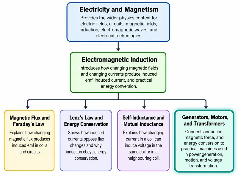
The diagram presents a 1-1-4 learning pathway for the Electromagnetic Induction cluster. It begins with Electricity and Magnetism as the wider physics context, then narrows to Electromagnetic Induction as the cluster overview. From there, it branches into four related pages: Magnetic Flux and Faraday’s Law, Lenz’s Law and Energy Conservation, Self-Inductance and Mutual Inductance, and Generators, Motors, and Transformers. The highlighted Generators, Motors, and Transformers branch indicates the final page in the cluster, helping students see how induction, magnetic force, and energy conversion come together in machines used for power generation, motion, and voltage transformation.
The Core Physical Idea
The core idea is that electric and magnetic systems can exchange energy through fields. A magnetic field can exert force on a current-carrying conductor. A changing magnetic flux can induce an emf in a coil. A changing current in one coil can induce voltage in another coil.
Generators, motors, and transformers use these ideas in different ways.
A generator uses changing magnetic flux to produce induced emf. In many generators, a coil rotates in a magnetic field, or a magnet rotates near a coil. This changes the magnetic flux linked with the coil, so Faraday’s law produces an emf.
A motor uses magnetic force to produce motion. When current flows through a coil in a magnetic field, forces act on opposite sides of the coil. These forces create a turning effect, allowing electrical energy to become mechanical energy.
A transformer uses mutual induction. Alternating current in the primary coil creates changing magnetic flux in the core. This changing flux links the secondary coil and induces voltage there. The number of turns in each coil determines whether the transformer steps voltage up or down.
Visual Guide to Generators, Motors, and Transformers
The following illustrations show the three major device types side by side: generators, motors, and transformers. They are grouped here so that students can first see the visual logic of energy conversion before moving into the separate explanations, equations, worked example, and applications.
1. Generator — Motion Produces Electricity
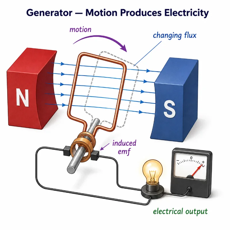
This illustration shows a simple generator with a coil rotating between north and south magnetic poles. As the coil turns, the magnetic flux through the coil changes, producing an induced emf. The induced electrical output is shown by the lamp and meter, helping students see why motion is needed for a generator to produce electricity.
2. Motor — Electricity Produces Motion
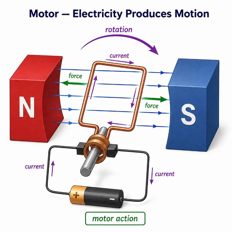
This illustration shows a simple electric motor with a current-carrying coil placed between north and south magnetic poles. Current flowing through the coil experiences magnetic forces on opposite sides, producing a turning effect and causing rotation. The diagram helps students connect electric current, magnetic field direction, force, and motor action.
3. Transformer — Changing Current Changes Voltage
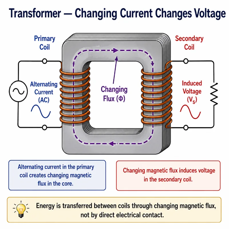
This illustration shows a transformer with a primary coil and a secondary coil wound around an iron core. Alternating current in the primary coil creates changing magnetic flux in the core, and this changing flux induces voltage in the secondary coil. The picture helps students see that transformer action depends on mutual induction, not direct electrical contact between the two circuits.
Generator: From Motion to Electrical Energy
A generator is a device that converts mechanical energy into electrical energy. In its simplest form, a coil rotates in a magnetic field. As the coil turns, the magnetic flux through the coil changes continuously. According to Faraday’s law, this changing flux induces an emf.
For a coil, Faraday’s law may be written as:
\( \varepsilon = -N\frac{\Delta\Phi}{\Delta t} \)
The generator does not create energy from nothing. Mechanical work is required to rotate the coil or magnet. That mechanical work is converted into electrical energy. Lenz’s law explains why the generator resists being turned when it supplies current to a load.
Coil or Magnet Rotates
Rotation changes the magnetic flux linked with the coil.Flux Changes with Time
Changing magnetic flux produces induced emf according to Faraday’s law.Current Flows in a Load
If the circuit is closed, the induced emf can drive current through an external device.Mechanical Work Is Required
Energy comes from the source turning the generator, such as a turbine, engine, wind rotor, or water wheel.Motor: From Electrical Energy to Motion
A motor works in the opposite energy direction from a generator. Instead of using motion to produce electricity, it uses electricity to produce motion.
When a current-carrying conductor is placed in a magnetic field, it experiences a force. For a straight wire of length \( L \), carrying current \( I \), at right angles to a magnetic field \( B \), the force magnitude is:
\( F = BIL \)
In a motor, the conductor is often wound into a coil. Forces on different sides of the coil act in opposite directions, producing a turning effect. With suitable design, the coil keeps rotating.
Electric motors appear in fans, pumps, washing machines, electric vehicles, lifts, hard drives, robots, drones, industrial tools, and many household devices.
Transformer: From One Voltage Level to Another
A transformer is a device that changes alternating voltage using mutual induction. It has at least two coils: a primary coil connected to an AC supply and a secondary coil connected to the output circuit.
Alternating current in the primary coil produces a changing magnetic field in the core. This changing field creates changing magnetic flux through the secondary coil. Faraday’s law then induces an emf in the secondary coil.
For an ideal transformer:
\( \frac{V_s}{V_p} = \frac{N_s}{N_p} \)
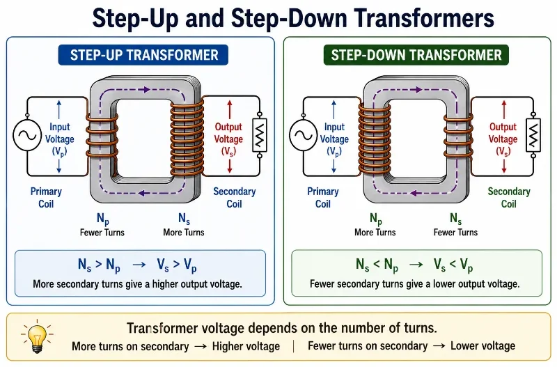
If the secondary coil has more turns than the primary coil, the transformer is a step-up transformer. If the secondary coil has fewer turns, it is a step-down transformer.
4. Step-Up and Step-Down Transformers
Three Machines, One Field-Based Story
It is easy to memorise generators, motors, and transformers as separate devices, but they are better understood as three organised uses of electromagnetic fields. The generator asks: how can motion create electricity? The motor asks: how can electricity create motion? The transformer asks: how can changing current in one circuit influence voltage in another circuit without direct contact?
In each case, the machine works because electric and magnetic effects are linked. Motion can change magnetic flux, current can experience force in a magnetic field, and changing current can create changing flux in a shared magnetic core. This shared field-based story is what makes the three devices part of the same electromagnetic induction cluster.
Comparing Generators, Motors, and Transformers
The three devices are easier to understand when compared by energy input, energy output, and the physical principle involved.
Generator
Input: mechanical motion. Output: electrical energy. Main idea: changing magnetic flux induces emf.Motor
Input: electrical energy. Output: mechanical motion. Main idea: magnetic force acts on current-carrying conductors.Transformer
Input: AC electrical energy. Output: AC electrical energy at a different voltage. Main idea: changing magnetic flux links two coils.Shared Theme
All three devices use magnetic fields to transfer or transform energy.5. Energy Flow in the Three Devices
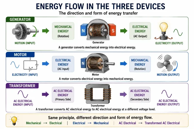
This illustration compares the energy flow in three electromagnetic devices. A generator converts mechanical energy into electrical energy, a motor converts electrical energy into mechanical motion, and a transformer transfers AC electrical energy to another AC electrical output at a different voltage level. The diagram helps students see that generators, motors, and transformers are related machines that organise energy flow in different directions.
Why Transformers Need Alternating Current
An ordinary transformer needs changing magnetic flux. Alternating current naturally changes direction and magnitude, so it produces changing magnetic flux in the transformer core.
A steady direct current does not continuously change after it becomes constant. Once the magnetic field is steady, the flux is steady, so no continuous emf is induced in the secondary coil.
This is why transformers are designed for AC systems or changing-current systems. The key requirement is not simply current, but changing current that produces changing magnetic flux.
Back EMF and Energy Conservation
Motors and generators both reveal energy conservation through electromagnetic opposition. In a generator, induced current produces effects that oppose the motion driving the generator. In a motor, the rotating coil can produce a back emf that opposes the applied voltage.
Back emf is not a mistake or nuisance. It is part of the energy balance of the motor. As the motor spins faster, back emf increases, reducing the net current drawn by the motor. When the motor is heavily loaded and slows down, back emf decreases, and the motor may draw more current.
This explains why motors can draw large current when starting or when stalled. At startup, the motor is not yet spinning fast, so back emf is small. The current is therefore limited mainly by the resistance and control circuit.
Advanced Analytical Modeling: The Practical Transformer Equivalent Circuit
While the ideal transformer equation assumes flawless energy coupling (\(V_s/V_p = N_s/N_p\)), real-world engineering devices face parasitic material limits. To track and optimize these non-ideal behaviors, university curricula represent the device using an lumped-parameter Equivalent Circuit Model. This circuit projects all secondary electrical quantities back to the primary side using the turns ratio \(a = N_p/N_s\):
In this advanced network diagram, the physical components map directly to the underlying loss mechanisms of electrodynamic field behavior:
- Winding Resistances (\(R_p\) and \(R_s\)): Account for real ohmic power losses (\(I^2R\)) as heat dissipated within the copper windings.
- Leakage Reactances (\(X_p\) and \(X_s\)): Model the reality that not all magnetic flux lines stay securely confined within the core. Some leak into the surrounding air, failing to couple the primary and secondary coils.
- The Core Magnetizing Branch (\(R_c \parallel X_m\)): Placed in parallel across the input, the shunt resistor \(R_c\) accounts for real core power waste (hysteresis loops and eddy currents), while the inductor \(X_m\) models the reactive energy required to continuously magnetize the domain walls of the iron core.
By applying standard complex circuit analysis to this framework, engineers can precisely forecast efficiency ratings and voltage regulations before building industrial scale power grid systems.
Electromechanical Field Distortions: Armature Reaction and Magnetic Saturation
In a simple motor model, students learn that a permanent external magnetic field (\(\mathbf{B}\)) exerts a linear Lorentz force on a current-carrying rotor coil. However, when an electric vehicle or industrial motor runs under heavy load conditions, the high current flowing through the rotating armature coils generates its own powerful, independent magnetic field.
The interaction of these two field systems creates a highly disruptive phenomenon known as Armature Reaction. The magnetic field from the armature distorts and twists the primary field lines out of shape:
This field distortion leads to two major engineering problems:
- Neutral Plane Shift: The magnetic neutral plane—the spatial orientation where the coil experiences zero induced emf—skews away from its geometric center. In brushed motors, this shift causes severe electric sparking and wear at the carbon contact brushes unless compensated for by auxiliary windings called interpoles.
- Flux Weakening: Because ferromagnetic cores exhibit non-linear behavior, the areas where the fields add together can hit Magnetic Saturation. The iron core reaches its physical limit for carrying flux lines, causing the crowded sections to saturate while the weakened sections drop off. The net result is a drop in total flux, which dramatically lowers the available motor torque.
This advanced perspective teaches students that electrical machines are not static environments. They are dynamic systems where currents actively deform the fields that drive them, requiring sophisticated electronic control algorithms to maintain peak performance.
Key Equations and What They Mean
Faraday’s law for an induced emf in a coil is:
\( \varepsilon = -N\frac{\Delta\Phi}{\Delta t} \)
\( \varepsilon \) — Induced emf, measured in volts. This is the voltage produced by changing magnetic flux.
\( N \) — Number of turns in the coil. More turns usually produce a larger induced emf.
\( \Delta\Phi \) — Change in magnetic flux through one turn of the coil.
\( \Delta t \) — Time taken for the flux change. A shorter time gives a larger induced emf.
The magnetic force on a straight current-carrying conductor at right angles to a magnetic field is:
\( F = BIL \)
\( F \) — Magnetic force on the conductor, measured in newtons.
\( B \) — Magnetic field strength, measured in tesla.
\( I \) — Current in the conductor, measured in amperes.
\( L \) — Length of conductor inside the magnetic field, measured in metres.
For an ideal transformer:
\( \frac{V_s}{V_p} = \frac{N_s}{N_p} \)
\( V_p \) — Primary voltage supplied to the input coil.
\( V_s \) — Secondary voltage produced at the output coil.
\( N_p \) — Number of turns in the primary coil.
\( N_s \) — Number of turns in the secondary coil.
For an ideal transformer, power is approximately conserved:
\( V_pI_p \approx V_sI_s \)
This means that if voltage is stepped up, current is stepped down, and if voltage is stepped down, current is stepped up, assuming losses are small.
Worked Example
Problem: A transformer has \( 200 \) turns in its primary coil and \( 1000 \) turns in its secondary coil. The primary voltage is \( 12 \ \text{V} \). Find the secondary voltage and state whether the transformer is step-up or step-down.
Given: \( N_p = 200 \), \( N_s = 1000 \), and \( V_p = 12 \ \text{V} \).
Method: Use the ideal transformer ratio:
\( \frac{V_s}{V_p} = \frac{N_s}{N_p} \)
Solution:
\( V_s = V_p\frac{N_s}{N_p} \)
\( V_s = 12\frac{1000}{200} \)
\( V_s = 12(5) \)
\( V_s = 60 \ \text{V} \)
Interpretation: The secondary voltage is \( 60 \ \text{V} \). Since the secondary coil has more turns than the primary coil and the voltage increases, this is a step-up transformer.
Worked Example Illustration
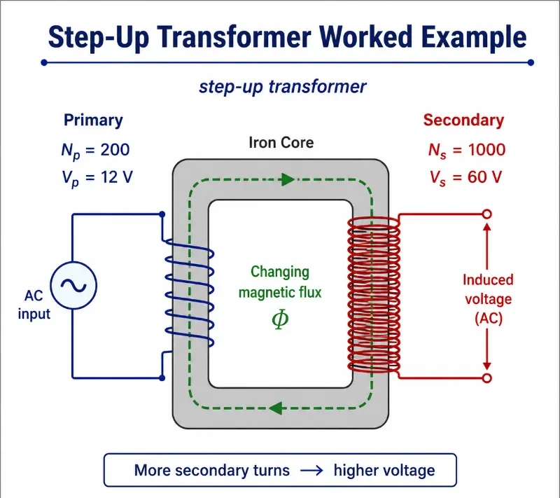
This worked-example illustration shows a step-up transformer with 200 turns in the primary coil and 1000 turns in the secondary coil. An AC input of 12 V on the primary side produces an induced AC output of 60 V on the secondary side. The diagram helps students see how a larger number of secondary turns gives a higher secondary voltage through changing magnetic flux in the iron core.
Advanced Analytical Mechanics: Deriving the Electromagnetic Wave Equation
The numerical problems above demonstrate how a rotating coil creates an alternating current. To understand the deeper physical reality behind this process, university-level electrodynamics shifts its focus from physical wires to empty space. In a complete vacuum—where there are no net electric charges (\(\rho = 0\)) and no conduction currents (\(\mathbf{J} = 0\))—Maxwell’s equations decouple into a highly symmetrical form:
$$ \nabla \cdot \mathbf{E} = 0 \quad \text{and} \quad \nabla \cdot \mathbf{B} = 0 $$
$$ \nabla \times \mathbf{E} = -\frac{\partial \mathbf{B}}{\partial t} \quad \text{and} \quad \nabla \times \mathbf{B} = \mu_0\varepsilon_0\frac{\partial \mathbf{E}}{\partial t} $$To isolate the electric field vector completely, we can apply the vector calculus identity for the curl of a curl (\(\nabla \times (\nabla \times \mathbf{A}) = \nabla(\nabla \cdot \mathbf{A}) – \nabla^2\mathbf{A}\)) directly to Faraday’s Law:
$$ \nabla \times (\nabla \times \mathbf{E}) = \nabla \times \left( -\frac{\partial \mathbf{B}}{\partial t} \right) $$
$$ \nabla(\nabla \cdot \mathbf{E}) – \nabla^2\mathbf{E} = -\frac{\partial}{\partial t}(\nabla \times \mathbf{B}) $$By substituting the empty-space Gauss’s law constraint (\(\nabla \cdot \mathbf{E} = 0\)) into the left side, and plugging the Ampère–Maxwell equation directly into the right side’s curl operator, the expression transforms into:
$$ \int_S (\nabla \times \mathbf{E}) \cdot d\mathbf{A} = \int_S \left( -\frac{\partial \mathbf{B}}{\partial t} \right) \cdot d\mathbf{A} $$
$$ \nabla^2 \mathbf{E} = \mu_0\varepsilon_0\frac{\partial^2 \mathbf{E}}{\partial t^2} $$This is the mathematical definition of a three-dimensional wave equation. Following the exact same steps for the magnetic field vector yields an identical wave expression:
$$ \nabla^2 \mathbf{B} = \mu_0\varepsilon_0\frac{\partial^2 \mathbf{B}}{\partial t^2} $$This calculus derivation shows that time-varying fields do not remain localized around a generator armature. Instead, they form a self-sustaining disturbance that propagates through empty space at a velocity of \(c = 1/\sqrt{\mu_0\varepsilon_0}\). This mathematically proves that light is an electromagnetic wave.
Advanced Treatment: Time-Dependent Generator Wave Functions
In the introductory worked example, we calculated the average voltage over an interval or assumed an ideal transformer turn ratio. For university physics and electrical engineering, we must upgrade this treatment to continuous, time-dependent wave functions to map the instantaneous dynamics of the system.
Consider the generator armature rotating at a uniform angular frequency \(\omega\). The instantaneous magnetic flux linking a single turn of the coil at any exact moment in time is governed by the angular position function:
$$ \Phi_B(t) = BA\cos(\omega t) $$To find the instantaneous electromotive force produced across a multi-turn coil system, we apply the rigorous derivative form of Faraday’s Law rather than an average rate of change:
$$ \varepsilon(t) = -N\frac{d\Phi_B}{dt} = -N \frac{d}{dt}\left[ BA\cos(\omega t) \right] $$Applying the chain rule to the trigonometric function converts the cosine into a negative sine, canceling the leading negative sign to yield the classic alternating voltage wave equation:
$$ \varepsilon(t) = NBA\omega\sin(\omega t) $$This advanced perspective allows us to analyze the system far beyond simple peak values. It models the real-world instantaneous power output, torque variations, and grid synchronization conditions essential for modern power systems engineering.
What Students Usually Get Wrong
Students often treat generators, motors, and transformers as separate facts to memorise. It is clearer to ask what each device receives, what it produces, and how magnetic fields help transfer energy.
Thinking Generators Create Energy
A generator converts mechanical energy into electrical energy. Mechanical work must be supplied to turn it.Confusing Motors and Generators
A motor uses electrical input to produce motion. A generator uses motion to produce electrical output.Forgetting That Transformers Need Changing Flux
Ordinary transformers do not work with steady DC because steady current does not produce continuously changing magnetic flux.Thinking Step-Up Means More Power Is Created
A step-up transformer increases voltage but decreases current in an ideal system. It does not create extra power.Ignoring Lenz’s Law
The opposition predicted by Lenz’s law explains why generators require work and why motors develop back emf.Focusing Only on Formulas
The formulas are useful, but the physical meaning is more important: fields transfer energy between motion and circuits.Where This Appears in Real Life
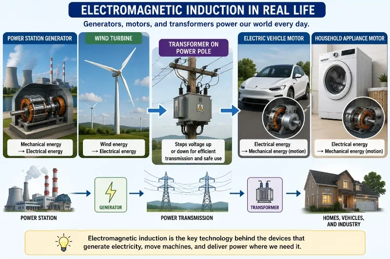
Generators, motors, and transformers are everywhere because they solve three essential problems: producing electricity, producing motion, and changing voltage for efficient energy transfer.
Power Stations
Turbines rotate generators to produce electricity from steam, falling water, wind, gas flow, or other energy sources.Electric Vehicles
Motors convert electrical energy from batteries into motion, and regenerative braking can convert motion back into electrical energy.Household Appliances
Fans, washing machines, refrigerators, vacuum cleaners, and pumps all use motors to create motion.Power Transmission
Transformers step voltage up for long-distance transmission and step it down again for safer local use.Phone Chargers and Adapters
Power supplies use transformer and induction principles, often combined with electronic switching circuits, to provide suitable output voltage.Renewable Energy Systems
Wind turbines and hydroelectric systems use generators, while transformers help connect generated power to the grid.Real-World Illustration
Bridge to University Thinking
At university level, generators, motors, and transformers are studied as electromagnetic energy-conversion systems. Students move beyond simple diagrams into magnetic circuits, rotating machinery, alternating-current analysis, power electronics, efficiency, losses, torque-speed curves, transformer equivalent circuits, and three-phase power systems.
The same basic principles remain: changing flux induces emf, current in magnetic fields experiences force, and energy must be conserved. What becomes more sophisticated is the modelling of real devices. Resistance, magnetic saturation, eddy currents, hysteresis, leakage flux, heating, mechanical friction, and electronic control all become important.
For engineering students, this topic is a gateway to electrical machines, mechatronics, renewable energy, robotics, power systems, electric vehicles, industrial automation, and smart-grid technologies. A simple coil in a magnetic field becomes the foundation for systems that move, generate, regulate, and distribute power.
Quick Interactive Check
Check Your Understanding of Generators, Motors, and Transformers
Use these short questions to test whether you understand the direction of energy conversion in each device.
What does a generator mainly convert?
Your thinking prompt: Think about what is supplied to a generator and what comes out.
Suggested answer: A generator converts mechanical energy into electrical energy using electromagnetic induction.
What does a motor mainly convert?
Your thinking prompt: Think about electricity producing motion.
Suggested answer: A motor converts electrical energy into mechanical motion using magnetic force on current-carrying conductors.
Why does a transformer need changing current?
Your thinking prompt: Think about changing magnetic flux.
Suggested answer: A transformer needs changing current because changing current produces changing magnetic flux, which induces voltage in the secondary coil.
Does a step-up transformer create extra power?
Your thinking prompt: Think about voltage, current, and energy conservation.
Suggested answer: No. A step-up transformer increases voltage but reduces current in an ideal system. It does not create extra power.
Why does a loaded generator require more mechanical work?
Your thinking prompt: Think about Lenz’s law and energy conservation.
Suggested answer: When a generator supplies current, induced effects oppose the motion that produces them. More mechanical work is needed because energy is being delivered to the electrical load.
Key takeaway: Generators, motors, and transformers are different arrangements of the same deep relationship between electric current, magnetic fields, motion, and energy conservation.
Review Questions and Answers
- What is the main function of a generator?Answer: A generator converts mechanical energy into electrical energy using electromagnetic induction.
- What is the main function of a motor?Answer: A motor converts electrical energy into mechanical motion using magnetic force on current-carrying conductors.
- What is the main function of a transformer?Answer: A transformer changes AC voltage levels using mutual induction between coils.
- Why does a generator produce emf when a coil rotates in a magnetic field?Answer: Rotation changes the magnetic flux through the coil, and Faraday’s law says changing flux induces emf.
- Why does a motor coil rotate in a magnetic field?Answer: Current in the coil experiences magnetic forces. These forces create a turning effect on the coil.
- Why do ordinary transformers require AC?Answer: Transformers require changing magnetic flux. AC produces changing current, which produces changing magnetic flux in the core.
- What is a step-up transformer?Answer: A step-up transformer has more secondary turns than primary turns, so the secondary voltage is higher than the primary voltage.
- What is a step-down transformer?Answer: A step-down transformer has fewer secondary turns than primary turns, so the secondary voltage is lower than the primary voltage.
Thought-Provoking Questions and Answers
- Why are motors and generators often described as reverse processes?Suggested answer: A generator uses motion to produce electrical energy, while a motor uses electrical energy to produce motion. The energy flow is reversed, although both depend on the relationship between current, magnetic fields, and motion.
- Why does a generator become harder to turn when it supplies more current?Suggested answer: Lenz’s law says induced currents oppose the change that produces them. When more electrical energy is delivered to a load, more mechanical work must be supplied to the generator.
- Why does a transformer not create extra energy when it increases voltage?Suggested answer: In an ideal transformer, power is conserved. Increasing voltage causes current to decrease, so energy is transferred rather than created.
- Why are transformers important for long-distance power transmission?Suggested answer: Transformers allow voltage to be increased for transmission. Higher voltage allows lower current for the same power, which reduces energy loss in transmission lines.
- Why are electrical machines a bridge between physics and engineering?Suggested answer: They turn field laws into useful devices. Physics explains the principles, while engineering shapes those principles into generators, motors, transformers, vehicles, factories, and power systems.
Numerical Problems and Solutions
- A transformer has \( N_p = 400 \) turns and \( N_s = 2000 \) turns. If \( V_p = 24 \ \text{V} \), find \( V_s \).Solution:\( \frac{V_s}{V_p} = \frac{N_s}{N_p} \)\( V_s = V_p\frac{N_s}{N_p} \)\( V_s = 24\frac{2000}{400} \)\( V_s = 24(5) \)\( V_s = 120 \ \text{V} \)Answer: The secondary voltage is \( 120 \ \text{V} \). This is a step-up transformer.
- A transformer steps \( 240 \ \text{V} \) down to \( 12 \ \text{V} \). If the primary coil has \( 1000 \) turns, find the number of secondary turns.Solution:\( \frac{V_s}{V_p} = \frac{N_s}{N_p} \)\( N_s = N_p\frac{V_s}{V_p} \)\( N_s = 1000\frac{12}{240} \)\( N_s = 1000(0.05) \)\( N_s = 50 \)Answer: The secondary coil has \( 50 \) turns.
- A straight wire of length \( 0.20 \ \text{m} \) carries a current of \( 5.0 \ \text{A} \) at right angles to a magnetic field of \( 0.30 \ \text{T} \). Find the magnetic force on the wire.Solution:\( F = BIL \)\( F = (0.30)(5.0)(0.20) \)\( F = 0.30 \ \text{N} \)Answer: The magnetic force on the wire is \( 0.30 \ \text{N} \).
- An ideal transformer has \( V_p = 120 \ \text{V} \), \( I_p = 2.0 \ \text{A} \), and \( V_s = 24 \ \text{V} \). Find the secondary current \( I_s \).Solution:For an ideal transformer:\( V_pI_p \approx V_sI_s \)\( I_s = \frac{V_pI_p}{V_s} \)\( I_s = \frac{(120)(2.0)}{24} \)\( I_s = 10 \ \text{A} \)Answer: The secondary current is \( 10 \ \text{A} \), assuming an ideal transformer.
Summary
Generators, motors, and transformers show how electricity and magnetism become useful technology. A generator converts motion into electrical energy by changing magnetic flux. A motor converts electrical energy into motion using magnetic force on current-carrying conductors. A transformer changes AC voltage using mutual induction between coils.
The three devices are connected by a common theme: energy is transferred through magnetic fields. Faraday’s law explains induced emf, Lenz’s law explains opposition and energy conservation, and magnetic force explains motor action.
In real life, these devices support electrical grids, household appliances, vehicles, factories, renewable energy systems, and electronic power supplies. They are among the most important practical outcomes of electromagnetic theory.
Final takeaway: Generators, motors, and transformers are different ways of arranging magnetic fields and currents so that energy can be generated, moved, transformed, and used.
Glossary
- Generator
- A device that converts mechanical energy into electrical energy using electromagnetic induction.
- Motor
- A device that converts electrical energy into mechanical motion using magnetic force on current-carrying conductors.
- Transformer
- A device that changes AC voltage levels using mutual induction between coils.
- Primary Coil
- The input coil of a transformer, connected to the AC supply.
- Secondary Coil
- The output coil of a transformer, where voltage is induced by changing magnetic flux.
- Step-Up Transformer
- A transformer that produces a higher secondary voltage than primary voltage.
- Step-Down Transformer
- A transformer that produces a lower secondary voltage than primary voltage.
- Back EMF
- An induced emf that opposes the applied voltage or the change causing it, commonly important in motors.
- Mutual Induction
- The process by which changing current in one coil induces emf in another nearby coil.
- Electrical Machine
- A device such as a motor or generator that converts energy between electrical and mechanical forms.
Frequently Asked Questions
What is the difference between a generator and a motor?
A generator converts mechanical energy into electrical energy, while a motor converts electrical energy into mechanical motion.
How does a generator produce electricity?
A generator changes magnetic flux through a coil. Faraday’s law says this changing flux induces an emf.
How does a motor produce motion?
A motor uses magnetic force on current-carrying conductors. These forces create a turning effect that produces rotation.
Why does a transformer need alternating current?
A transformer needs changing magnetic flux. Alternating current produces changing magnetic flux, which induces voltage in the secondary coil.
Does a step-up transformer create more energy?
No. A step-up transformer increases voltage but decreases current in an ideal system. It transfers energy; it does not create energy.
External References
- OpenStax University Physics: Electric Generators and Back EMF — Explains generator action and the role of induced emf in rotating electrical machines.
- OpenStax Physics: Electromagnetic Induction — Covers the relationship between electric and magnetic fields in generators, motors, and transformers.
- PhET: Generator Simulation — Interactive simulation showing how spinning magnets and coils can generate electricity.
- MIT OpenCourseWare: Magnetic Circuits and Transformers — University-level lecture material on magnetic circuits and transformer principles.