Prepare for University Studies & Career Advancement
Self-Inductance and Mutual Inductance
Self-inductance and mutual inductance explain how changing current can create electrical effects in coils. They are part of electromagnetic induction, but they shift attention from moving magnets and rotating coils to circuits whose own changing currents produce changing magnetic fields.
In self-inductance, a changing current in a coil changes the magnetic flux linked with that same coil. The coil responds by producing an induced emf that opposes the change in current. This is why an inductor resists sudden changes in current.
In mutual inductance, a changing current in one coil changes the magnetic flux linked with a nearby second coil. The second coil then experiences an induced emf. This is the physical idea behind transformers, wireless charging, induction sensors, and many signal-coupling devices.
The deeper lesson is that a circuit is not merely a path for current. A circuit also creates magnetic fields, stores magnetic energy, and can influence other circuits nearby. Inductance is the measure of this magnetic memory.
Self-inductance happens within one circuit, while mutual inductance happens between two circuits linked by changing magnetic flux.
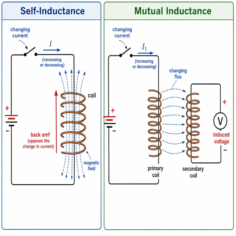
This illustration compares self-inductance and mutual inductance side by side. In self-inductance, a changing current in one coil produces a changing magnetic field, causing a back emf in the same circuit that opposes the change in current. In mutual inductance, a changing current in the primary coil produces changing magnetic flux that links to a nearby secondary coil, inducing voltage in the second circuit. The diagram helps students see that both effects come from changing magnetic flux, but self-inductance acts within one circuit while mutual inductance acts between two magnetically linked circuits.
Learning Pathway: From Changing Current to Induced Voltage
This page sits inside the Electromagnetic Induction cluster. It builds on magnetic flux, Faraday’s Law, and Lenz’s Law, then prepares students to understand transformers, inductors, coupled coils, and energy storage in magnetic fields.
Applies induction ideas to machines that convert motion, electricity, voltage, and energy in practical systems.
Core Physical Idea
A current in a wire produces a magnetic field. If the current changes, the magnetic field also changes. If the wire is shaped into a coil, the changing magnetic field links strongly with the coil and produces induced emf.
This gives rise to two related effects:
Self-inductance: a changing current in a coil induces an emf in the same coil.
Mutual inductance: a changing current in one coil induces an emf in another nearby coil.
The induced emf always follows Lenz’s Law. It acts in a direction that opposes the change in current or magnetic flux that caused it. For this reason, inductors do not oppose current itself. They oppose changes in current.
This is an important distinction. A steady direct current can flow through an ideal inductor without induced emf. But when the current is increasing or decreasing, the inductor produces a back emf that resists the change.
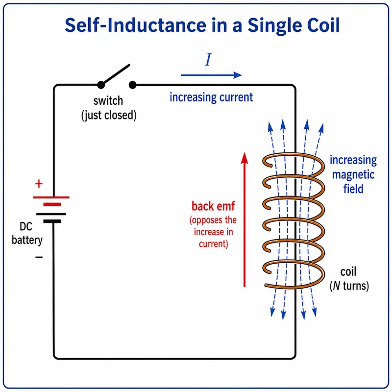
Pictorial Illustration 1: Self-Inductance in a Single Coil
A changing current in a coil produces a changing magnetic field, causing the coil to induce a back emf in itself.
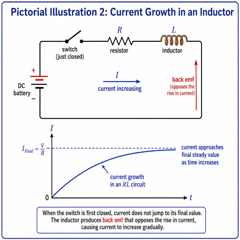
Pictorial Illustration 2: Current Growth in an Inductor
In an RL circuit, current rises gradually because the inductor produces a back emf that opposes the increase in current.
This illustration shows current growth in a circuit containing a battery, switch, resistor, and inductor. When the switch is first closed, the current does not jump immediately to its final steady value. Instead, the increasing current produces a changing magnetic field in the inductor, and the inductor responds with a back emf that opposes the rise in current. The graph shows the current increasing gradually with time, helping students see why inductors delay sudden changes in current.
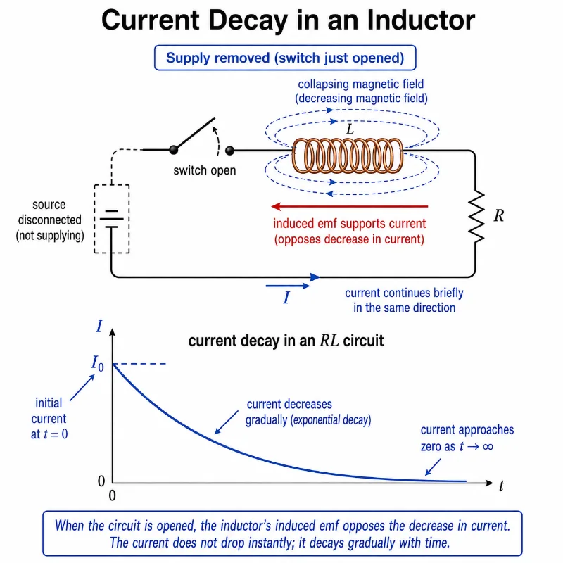
Pictorial Illustration 3: Current Decay in an Inductor
When the supply is removed, an inductor temporarily supports the original current direction, so current decreases gradually instead of stopping instantly.
This illustration shows current decay in an RL circuit after the supply has been removed and the switch is opened. The inductor’s magnetic field begins to collapse, producing an induced emf that supports the original current direction and opposes the decrease in current. The graph shows that current does not fall to zero instantly, but decays gradually with time. This helps students understand why inductors can briefly keep current flowing and may produce voltage surges when circuits are switched off.
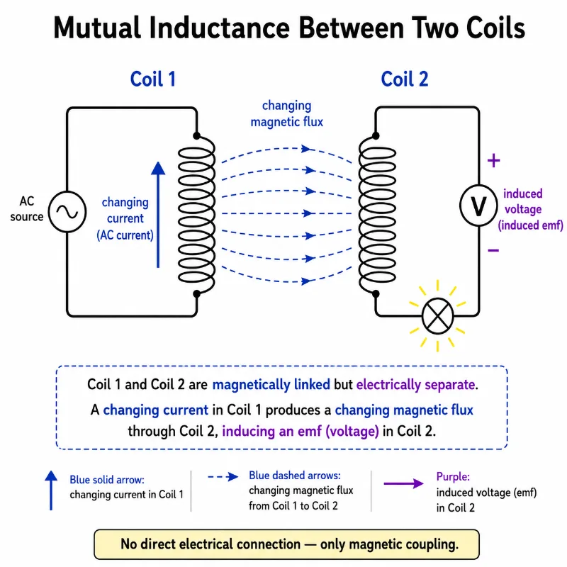
Pictorial Illustration 4: Mutual Inductance Between Two Coils
A changing current in one coil produces changing magnetic flux that links a nearby second coil and induces voltage in it.
This illustration shows mutual inductance between two nearby coils. Coil 1 is connected to an AC source, so its changing current produces a changing magnetic field and changing magnetic flux. Some of this changing flux links with Coil 2, even though the two coils are electrically separate. As a result, an induced emf appears in Coil 2, shown by the voltmeter and lamp. The picture helps students understand that mutual inductance is a magnetic interaction between circuits: energy is transferred through changing magnetic flux rather than through direct electrical contact.
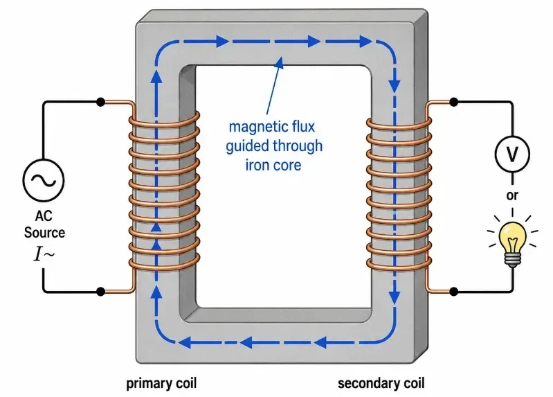
Pictorial Illustration 5: Magnetic Coupling Through an Iron Core
An iron core improves mutual inductance by guiding magnetic flux from the primary coil to the secondary coil.
This illustration shows how an iron core strengthens magnetic coupling between two coils. The primary coil is connected to an AC source, producing a changing current and a changing magnetic flux. The iron core guides much of this flux through a closed path so that it links strongly with the secondary coil. This stronger flux linkage induces voltage in the secondary circuit, shown by the voltmeter or lamp. The picture helps students see why transformers and coupled coils often use iron cores: the core does not conduct electricity between the coils, but it provides an easier magnetic path for flux transfer.
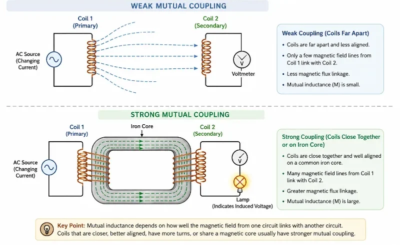
Pictorial Illustration 6: Weak and Strong Mutual Coupling
Mutual inductance is weak when little magnetic flux links the coils, and strong when many flux lines connect the two circuits.
This illustration compares weak and strong mutual coupling between two coils. In weak coupling, the coils are far apart, so only a small part of the magnetic field from the primary coil links with the secondary coil. The induced voltage is therefore small. In strong coupling, the coils are close together and share an iron core, which guides more magnetic flux from one coil to the other. The picture helps students see that mutual inductance depends on how effectively changing magnetic flux connects two circuits.
Key Equations and What They Mean
\( \lambda = N\Phi_B \) — Flux linkage. It is the total magnetic flux linked with all turns of a coil. \( N \) is the number of turns and \( \Phi_B \) is the magnetic flux through one turn.
\( L = \frac{N\Phi_B}{I} \) — Self-inductance of a coil. It measures how much flux linkage is produced per unit current in the same coil.
\( \varepsilon_L = -L\frac{\Delta I}{\Delta t} \) — Induced emf due to self-inductance, written for a finite change in current. The negative sign shows that the induced emf opposes the change in current.
\( \varepsilon_L = -L\frac{dI}{dt} \) — Instantaneous form of the self-induction equation. This is used when current changes continuously with time.
\( L = \mu \frac{N^2 A}{l} \) — Approximate inductance of a long solenoid. \( \mu \) is the magnetic permeability of the core material, \( N \) is the number of turns, \( A \) is the cross-sectional area, and \( l \) is the length of the solenoid.
\( U = \frac{1}{2}LI^2 \) — Energy stored in the magnetic field of an inductor. A larger inductance or larger current means more magnetic energy is stored.
\( \tau = \frac{L}{R} \) — Time constant of an RL circuit. It gives a measure of how quickly current rises or falls in a circuit containing resistance and inductance.
\( M = \frac{N_2\Phi_{21}}{I_1} \) — Mutual inductance between two coils. It measures how much flux linkage in coil 2 is produced per unit current in coil 1.
\( \varepsilon_2 = -M\frac{\Delta I_1}{\Delta t} \) — Induced emf in coil 2 due to a changing current in coil 1. The faster the current changes in coil 1, the larger the induced emf in coil 2.
\( \varepsilon_2 = -M\frac{dI_1}{dt} \) — Instantaneous form of the mutual induction equation.
\( k = \frac{M}{\sqrt{L_1L_2}} \) — Coupling coefficient. It describes how strongly two coils are magnetically linked. A value closer to 1 means stronger coupling.
Calculus Derivation: Stored Magnetic Energy and Field Energy Density
An inductor does not dissipate energy like a resistor; instead, it stores energy in its growing magnetic field. To understand where the equation \(U = \frac{1}{2}LI^2\) originates, we look at the calculus of electrical work. The instantaneous power \(P\) required by an external source to push current against an inductor’s back emf (\(\varepsilon_L = L \frac{dI}{dt}\)) is given by:
$$ P(t) = \varepsilon_L I = L I \frac{dI}{dt} $$
Because power is the rate of doing work (\(P = \frac{dW}{dt}\)), we can set up an integral to calculate the total work done (energy stored) as the current increases from zero to a final steady-state value \(I\):
$$ dW = P \, dt = L I \left(\frac{dI}{dt}\right) dt = L I \, dI $$
$$ U = \int_0^I L I’ \, dI’ = L \left[ \frac{(I’)^2}{2} \right]_0^I = \frac{1}{2}LI^2 $$
At the university level, we take this a step further by mapping this energy directly to the geometry of the magnetic field itself. For a long solenoid where inductance is \(L = \frac{\mu N^2 A}{l}\) and the interior magnetic field is \(B = \frac{\mu N I}{l}\), substituting these expressions into our energy formula yields:
$$ U = \frac{1}{2} \left( \frac{\mu N^2 A}{l} \right) \left( \frac{B l}{\mu N} \right)^2 = \frac{B^2}{2\mu} (A l) $$
Since \(A l\) represents the physical interior volume (\(V\)) of the solenoid, we divide the total energy by volume to determine the magnetic energy density (\(u_B\)) stored anywhere in free space or a magnetic medium:
$$ u_B = \frac{U}{V} = \frac{B^2}{2\mu} $$
Mathematical Analysis: Differential Equations for RL Transient Dynamics
When a switch in an inductive circuit is thrown, the resulting current adjustments are not instantaneous. By applying Kirchhoff’s Voltage Law (KVL) around a single loop containing a constant DC voltage source \(V_0\), a resistor \(R\), and an inductor \(L\), we obtain a first-order linear differential equation:
$$ V_0 – L\frac{dI}{dt} = I R \Rightarrow L\frac{dI}{dt} + I R = V_0 $$
To solve this for current growth over time, we separate the variables \(I\) and \(t\) and integrate, assuming an initial condition where \(I(0) = 0\):
where \(\tau = \frac{L}{R}\) is the structural inductive time constant. Conversely, if the voltage source is shorted out and the current decays from its maximum baseline value \(I_0\), the KVL equation simplifies to \(L\frac{dI}{dt} + IR = 0\), which yields an uninhibited exponential decay function:
$$ I(t) = I_0 e^{-\frac{t}{\tau}} $$
This rigorous presentation shows engineering students exactly why current lags behind voltage changes, giving them the differential calculus toolkit required for university circuit analytics.
Self-Inductance: A Coil Opposing Its Own Current Change
Self-inductance is easiest to understand by imagining a coil connected to a source whose current is increasing. As current increases, the magnetic field inside the coil becomes stronger. This means the magnetic flux linked with the coil is changing.
By Faraday’s Law, changing magnetic flux induces an emf. Because the changing flux is produced by the coil’s own current, the induced emf appears in the same coil. By Lenz’s Law, this induced emf opposes the increase in current.
If the current is decreasing, the inductor responds differently. It induces an emf that tries to keep the current flowing in the original direction. In both cases, the inductor opposes change, not the existence of current itself.
This is why inductors are sometimes described as electrical components with “inertia.” Just as a massive object resists sudden changes in motion, an inductor resists sudden changes in current.
Back EMF: The Electrical Sign of Resistance to Change
The induced emf in self-inductance is often called back emf. The word “back” does not mean that electricity literally travels backward. It means that the induced emf acts against the change being imposed on the circuit.
When current is rising, the back emf acts against the source and slows the rise. When current is falling, the induced emf acts to keep current going. The direction changes depending on whether the current is increasing or decreasing.
This explains why circuits with inductors behave differently from circuits with only resistors. In a resistor-only circuit, current changes almost immediately when voltage changes. In an inductor circuit, the magnetic field needs time to build up or collapse.
Mutual Inductance: One Coil Influencing Another Coil
Mutual inductance occurs when two circuits are linked by magnetic flux. If the current in the first coil changes, its magnetic field changes. If some of this changing magnetic field passes through the second coil, an emf is induced in the second coil.
The first coil is often called the primary coil, and the second coil is called the secondary coil. These names are common in transformer discussions, but the idea applies to many other devices too.
The two coils do not need to touch electrically. Energy can be transferred through the changing magnetic field. This is why transformers can transfer electrical energy between separate circuits while keeping them electrically isolated.
Mutual inductance depends on coil shape, number of turns, distance between coils, orientation, core material, and how much magnetic flux from one coil links the other coil.
Worked Example: Back EMF in an Inductor
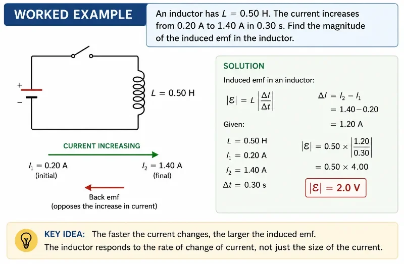
Problem: A coil has an inductance of \( 0.50 \ \text{H} \). The current through the coil increases from \( 0.20 \ \text{A} \) to \( 1.40 \ \text{A} \) in \( 0.30 \ \text{s} \). Find the magnitude of the induced emf.
Answer: The magnitude of the induced emf is \( 2.0 \ \text{V} \).
The negative sign in the full equation \( \varepsilon_L = -L\frac{\Delta I}{\Delta t} \) tells us the direction of the induced emf. Since the current is increasing, the induced emf acts to oppose that increase.
Worked Example Illustration
A faster change in current produces a larger induced emf, so the inductor responds to the rate of current change.
This worked example illustration shows a coil with inductance 0.50 H as the current increases from 0.20 A to 1.40 A in 0.30 s. The change in current produces a changing magnetic field, so the inductor induces a back emf that opposes the rise in current. Using the self-induction equation, the magnitude of the induced emf is 2.0 V. The picture helps students see that an inductor responds not only to current, but to how quickly the current changes.
Worked Example: Induced EMF by Mutual Inductance
Problem: Two coils have mutual inductance \( M = 0.080 \ \text{H} \). The current in coil 1 decreases from \( 3.0 \ \text{A} \) to \( 1.0 \ \text{A} \) in \( 0.50 \ \text{s} \). Find the magnitude of the induced emf in coil 2.
Answer: The magnitude of the induced emf in coil 2 is \( 0.32 \ \text{V} \).
Common Misconceptions: What Students Usually Get Wrong
Thinking Inductors Oppose Current Itself
An ideal inductor does not oppose steady current. It opposes changes in current. This is why the rate of change \( \frac{dI}{dt} \), not just \( I \), appears in the induced emf equation.
Forgetting the Meaning of the Negative Sign
The negative sign in \( \varepsilon = -L\frac{dI}{dt} \) or \( \varepsilon = -M\frac{dI}{dt} \) represents Lenz’s Law. It shows opposition to change, not simply a negative numerical answer.
Confusing Self-Inductance and Mutual Inductance
Self-inductance involves one coil inducing emf in itself. Mutual inductance involves one coil inducing emf in another coil.
Assuming a Constant Current Always Produces Induced EMF
A steady current may produce a steady magnetic field, but it does not produce induced emf unless the magnetic flux is changing.
Thinking Energy Disappears When Current Falls
The magnetic field around an inductor stores energy. When current decreases, this stored energy can return to the circuit.
Treating Mutual Inductance as Electrical Contact
Two coils can influence each other magnetically even when they are not electrically connected. The link is changing magnetic flux, not direct conduction.
Real-World Applications
Inductors in Electronic Circuits
Inductors are used in filters, power supplies, radio circuits, and timing circuits because they respond strongly to changing current.
Transformers
Transformers use mutual inductance between coils to step AC voltage up or down. Their operation depends on changing magnetic flux linking primary and secondary coils.
Wireless Charging
Wireless charging uses magnetic coupling between coils. A changing current in a charging pad induces voltage in a coil inside the device being charged.
Ignition Systems
Inductive effects can produce large voltage pulses when current changes quickly. This principle is used in ignition coils and switching circuits.
Electric Motors and Generators
Inductance affects how currents build up and change in motor and generator windings, influencing performance, efficiency, and control.
Signal Coupling and Isolation
Mutual inductance can transfer signals between circuits while maintaining electrical isolation, which helps protect sensitive equipment.
Real-World Illustration
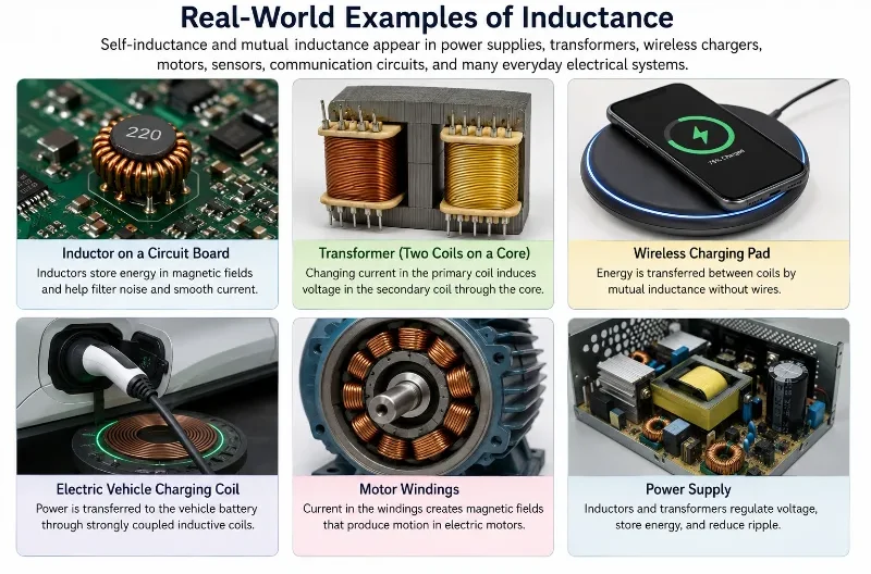
Self-inductance and mutual inductance appear in many everyday technologies, from power supplies and motors to transformers and wireless charging systems.
This illustration shows several real-world examples of inductance in modern electrical systems. Inductors on circuit boards help store magnetic energy, filter noise, and smooth changing current. Transformers use mutual inductance between coils to transfer energy and change voltage levels. Wireless charging pads and electric vehicle charging coils use magnetic coupling to transfer power without direct metal contact. Motor windings use current and magnetic fields to produce motion, while power supplies rely on inductors and transformers to regulate voltage and reduce ripple. The picture helps students see that self-inductance and mutual inductance are not only textbook ideas, but practical principles behind many devices used in daily life.
Bridge to University Thinking
At school level, inductance is often introduced through simple equations and coil diagrams. At university level, the same idea becomes part of a much larger field theory. Students learn that magnetic fields store energy, electromagnetic fields carry momentum, and changing fields can produce waves.
Self-inductance also becomes important in circuit analysis. In an RL circuit, current changes gradually because the inductor stores and releases magnetic energy. In AC circuits, inductors produce reactance, phase difference, filtering behaviour, and frequency-dependent responses.
Mutual inductance becomes central in transformer design, wireless power transfer, signal isolation, electric machines, communication systems, and high-frequency electronics. The simple school idea of “one coil inducing voltage in another” grows into a powerful engineering principle.
A good way to think about this topic is: resistors dissipate energy, capacitors store energy in electric fields, and inductors store energy in magnetic fields. This comparison becomes very useful in advanced physics and engineering.
Quick Interactive Check
Quick Check: Self-Inductance and Mutual Inductance
1. What does an ideal inductor mainly oppose?
A. Current itself
B. Voltage itself
C. Change in current
D. Resistance in a wire
Answer: C. An ideal inductor opposes changes in current. It produces induced emf when current is increasing or decreasing.
2. What is self-inductance?
A. A coil inducing emf in itself due to its own changing current
B. A magnet pushing a current through a wire
C. A resistor producing heat
D. A battery producing constant voltage
Answer: A. Self-inductance occurs when a changing current in a coil changes its own magnetic flux linkage and induces emf in the same coil.
3. What is mutual inductance?
A. A coil inducing emf in another coil through changing magnetic flux
B. A coil becoming hotter due to resistance
C. A wire carrying steady direct current
D. A switch stopping current completely
Answer: A. Mutual inductance occurs when changing current in one coil induces emf in another coil through magnetic coupling.
4. Why does the equation \( \varepsilon_L = -L\frac{dI}{dt} \) contain a negative sign?
A. Because voltage is always negative in an inductor
B. Because current cannot pass through an inductor
C. Because the induced emf opposes the change in current
D. Because inductance is always negative
Answer: C. The negative sign represents Lenz’s Law. The induced emf acts in a direction that opposes the current change that produces it.
5. What happens to the induced emf if the current changes more rapidly?
A. It becomes smaller
B. It becomes larger
C. It becomes zero
D. It becomes independent of inductance
Answer: B. Induced emf depends on the rate of change of current. A faster change in current produces a larger induced emf.
Review Questions and Answers
Review Questions
1. What is self-inductance?
Self-inductance is the property of a coil or circuit by which a changing current induces an emf in the same coil or circuit.
2. What is mutual inductance?
Mutual inductance is the property by which a changing current in one coil induces an emf in another nearby coil through changing magnetic flux.
3. Why is the induced emf in an inductor called back emf?
It is called back emf because it acts against the change in current that produces it.
4. Does an inductor oppose steady current?
An ideal inductor does not oppose steady current. It opposes changes in current.
5. What physical quantity is stored in an inductor?
An inductor stores energy in its magnetic field.
6. What is the unit of inductance?
The unit of inductance is the henry, symbol \( \text{H} \).
7. Why does an iron core increase mutual inductance?
An iron core guides and concentrates magnetic flux, allowing more flux from one coil to link with another coil.
8. What does the time constant \( \tau = \frac{L}{R} \) describe?
It describes how quickly current rises or falls in an RL circuit. A larger time constant means a slower change in current.
Thought-Provoking Questions and Answers
Deeper Thinking
1. Why can an inductor be compared to inertia in mechanics?
Inertia resists changes in motion, while inductance resists changes in current. Both ideas describe resistance to sudden change, although the physical mechanisms are different.
2. Why does self-inductance support energy conservation?
The induced emf opposes the change that produces it. Energy must be supplied to build the magnetic field, and this energy can later be returned when the field collapses.
3. Why is mutual inductance useful even when two circuits are not electrically connected?
Mutual inductance allows energy or signals to be transferred magnetically. This can provide electrical isolation, which is useful for safety and circuit protection.
4. Why does a transformer require changing current rather than steady direct current?
A transformer works through changing magnetic flux. A steady direct current produces a steady magnetic field after the initial moment, so it does not continuously induce emf in the secondary coil.
5. Why can switching off an inductive circuit sometimes produce a large voltage?
If current is forced to decrease very quickly, \( \frac{dI}{dt} \) becomes large. Since induced emf is proportional to the rate of change of current, a large voltage can appear briefly.
Numerical Problems and Solutions
Practice Problems
1. An inductor has \( L = 0.20 \ \text{H} \). The current changes from \( 0 \ \text{A} \) to \( 3.0 \ \text{A} \) in \( 0.60 \ \text{s} \). Find the magnitude of the induced emf.
4. Two coils have mutual inductance \( M = 0.12 \ \text{H} \). The current in coil 1 changes by \( 5.0 \ \text{A} \) in \( 0.25 \ \text{s} \). Find the magnitude of the induced emf in coil 2.
6. A coil has \( N = 200 \) turns. The magnetic flux through each turn is \( 4.0 \times 10^{-5} \ \text{Wb} \) when the current is \( 0.80 \ \text{A} \). Find the self-inductance.
Self-inductance and mutual inductance show how changing current and changing magnetic flux are connected. In self-inductance, a coil induces emf in itself when its own current changes. In mutual inductance, one coil induces emf in another coil when the current in the first coil changes.
The central rule is Lenz’s Law: induced effects oppose the change that produces them. This is why inductors resist sudden changes in current and why changing magnetic fields can transfer energy between separate circuits.
Inductance is not only a formula topic. It helps explain transformers, wireless charging, power electronics, motor windings, signal coupling, and energy storage in magnetic fields.
Glossary
Inductance
The property of a circuit or coil that relates changing current to induced emf.
Self-Inductance
The ability of a coil to induce emf in itself when its own current changes.
Mutual Inductance
The ability of one coil to induce emf in another coil through changing magnetic flux.
Back EMF
An induced emf that opposes the change in current that produces it.
Flux Linkage
The total magnetic flux linked with all turns of a coil, usually written as \( N\Phi_B \).
Inductor
A circuit component designed to store energy in a magnetic field and oppose changes in current.
Henry
The SI unit of inductance, symbol \( \text{H} \).
RL Circuit
A circuit containing resistance and inductance, often used to study current growth and decay.
Time Constant
A measure of how quickly current changes in an RL circuit, given by \( \tau = \frac{L}{R} \).
Coupling Coefficient
A number that describes how strongly two coils are magnetically linked.
Frequently Asked Questions
FAQ: Self-Inductance and Mutual Inductance
1. Is inductance the same as resistance?
No. Resistance opposes current and converts electrical energy into heat. Inductance opposes changes in current and stores energy in a magnetic field.
2. Why does an inductor resist sudden current changes?
A sudden current change would cause a rapid change in magnetic flux. The inductor responds by inducing an emf that opposes the change.
3. Can self-inductance happen in a straight wire?
Yes, any current-carrying conductor has some self-inductance, but coils are used because they greatly increase magnetic flux linkage.
4. Why are coils used instead of single loops?
More turns increase flux linkage, making inductive effects stronger.
5. Why does mutual inductance matter in transformers?
A transformer works because changing current in the primary coil induces emf in the secondary coil through mutual inductance.
6. Does mutual inductance require physical contact between coils?
No. The coils can be electrically separate. They are linked by changing magnetic flux.
7. Why is alternating current useful for mutual induction?
Alternating current continuously changes direction and magnitude, producing changing magnetic flux that can induce emf in another coil.
8. What happens to the magnetic energy when current in an inductor decreases?
The stored magnetic energy can be returned to the circuit as the magnetic field collapses.