Prepare for University Studies & Career Advancement
Lenses and Image Formation
Lenses are among the most important optical devices in everyday life. They help us read, take photographs, project images, correct vision, observe microscopic cells, and study distant stars. A lens may look like a simple piece of transparent material, but its power comes from a deep physical idea: when light changes speed as it enters and leaves a material, its direction changes. This bending of light is called refraction.
The study of lenses and image formation helps students connect ray diagrams, geometry, measurement, and real-world optical design. It also prepares them for later topics such as cameras, microscopes, telescopes, the human eye, optical fibres, and modern imaging technologies. Instead of treating lens diagrams as abstract drawings, this page explains how lenses guide light to form images that may be real or virtual, upright or inverted, magnified or diminished.
At its heart, image formation is a question of where light rays appear to meet. If actual rays meet after passing through a lens, a real image is formed. If rays only appear to come from a point when traced backward, a virtual image is formed. This simple distinction explains why a projector can throw an image onto a screen, while a magnifying glass creates an enlarged image that appears to exist behind the lens.
Lenses guide light to help us read, photograph, project images, observe tiny details, and study distant objects in the sky.
This artist impression introduces lenses and image formation through familiar examples. Spectacles, a magnifying glass, camera, projector, microscope, and telescope are shown around a central transparent lens, with gentle light paths suggesting how refraction redirects light. The image avoids technical ray-diagram detail while helping students see that lenses connect everyday vision, photography, projection, microscopy, astronomy, and modern optical technologies.
How This Page Fits into Light and Optics
Lenses belong to the wider study of light and optics. They build directly on reflection, refraction, ray diagrams, and the behaviour of light at boundaries between materials.
Extends ray optics into interference, diffraction, and the wave nature of light.
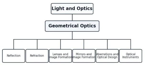
This 1-1-6 tree chart shows how the six Geometrical Optics sub-pages sit under the wider Light and Optics section.
This clean hierarchy chart presents the Geometrical Optics cluster as a simple 1-1-6 structure. Light and Optics appears as the top-level parent, Geometrical Optics appears as the second-level page, and six related sub-pages branch from it: Reflection, Refraction, Lenses and Image Formation, Mirrors and Image Formation, Aberrations and Optical Design, and Optical Instruments. The chart is designed to help students understand the page structure clearly without extra icons or decorative elements.
The Context of Lenses: History, Evolution, and Future Frontiers
Humanity’s mastery over light did not happen overnight. The development of lenses mirrors our drive to uncover the microscopic and astronomical secrets of our universe.
The Historical Journey
The earliest known manufactured lens is the Nimrud lens, a piece of rock crystal polished over 3000 years ago in ancient Assyria, likely used as a magnifying glass or burning glass. However, the foundational physics of refraction was truly unlocked in the 10th century by Ibn Sahl, who detailed how curved mirrors and lenses bend light, a principle later rediscovered and expanded by Willebrord Snellius in 1621 (Snell’s Law).
By the early 17th century, the accidental alignment of two glass lenses gave rise to the telescope and the microscope, completely reshaping human science. Hans Lippershey, Galileo Galilei, and Antonie van Leeuwenhoek turned rough glass spheres into profound windows pointing toward new moons and teeming microscopic life fields.
Modern Physics Challenges
For centuries, optical design relied on the **Lensmaker’s Equation**, which assumes a single uniform material with a fixed index of refraction. Today, engineers face the ultimate limits of traditional glass physics. As light travels through a standard lens, dispersion causes different wavelengths to focus at different points (chromatic aberration), while the spherical shape causes edge rays to focus closer than central rays (spherical aberration). Overcoming these issues with complex multi-lens configurations adds substantial physical weight, volume, and manufacturing cost to consumer electronics and deep-space hardware.
The Future: Meta-Lenses and Adaptive Optics
The field of lens design is currently undergoing its most revolutionary evolution since the Renaissance:
Flat Metamaterial Lenses (Metalenses): Instead of relying on bulk glass thickness and heavy geometry to refract light slowly, metalenses utilize a flat array of sub-wavelength nanostructures. These features orchestrate the phase and wavefront of incoming light instantly on a flat surface, promising to make camera bumps on smartphones entirely obsolete.
Gradient-Index (GRINDEX) Optics: Modern manufacturing allows lenses to mimic the natural structure of the human eye, where the index of refraction varies continuously across the physical material rather than being constant, allowing a single flat slice of material to act as a powerful focusing element.
What a Lens Really Does
A lens does not “create” light. It redirects light that already exists. When light from an object reaches a lens, different parts of the lens bend the rays by different amounts. The lens shape is designed so that the rays either come together or spread apart in a controlled way.
A converging lens is thicker at the centre than at the edges. It bends parallel rays inward so that they meet at a focal point. A diverging lens is thinner at the centre than at the edges. It bends parallel rays outward so that they appear to come from a focal point on the same side as the incoming light.
This is why lenses are not just pieces of glass or plastic. Their curved surfaces are carefully shaped to control the paths of light rays. The image formed by a lens depends on the lens type, the object distance, and the focal length.
Key Parts of a Lens Diagram
A lens diagram uses a few standard points and lines. Once these are understood, most ray diagrams become much easier to interpret.
Principal axis
The straight reference line passing through the centre of the lens. Ray diagrams are usually drawn around this line.
Optical centre
The central point of a thin lens. A ray passing through the optical centre is usually drawn as travelling straight through without deviation.
Principal focus
The point where rays parallel to the principal axis meet after passing through a converging lens, or appear to come from after passing through a diverging lens.
Focal length
The distance from the optical centre of the lens to the principal focus. It is usually represented by f.
Object distance
The distance from the object to the optical centre of the lens. It is usually represented by u.
Image distance
The distance from the image to the optical centre of the lens. It is usually represented by v.
Converging Lenses
A converging lens is also called a convex lens. It is thicker in the middle and thinner at the edges. When parallel rays of light enter a converging lens, the rays are bent toward the principal axis and meet at the focal point.
The behaviour of a converging lens depends strongly on where the object is placed. If the object is far from the lens, the image may be real, inverted, and smaller. If the object is closer, the image may become larger. If the object is placed inside the focal length, the image becomes virtual, upright, and magnified.
Standard Rays for a Converging Lens
Three common rays are used to construct images formed by a converging lens.
A ray parallel to the principal axis passes through the focal point on the far side of the lens.
A ray passing through the optical centre continues in a straight line.
A ray passing through the focal point before reaching the lens emerges parallel to the principal axis.
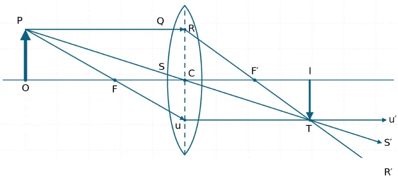
A convex lens forms a real, inverted image where the refracted rays from the top of the object meet on the opposite side of the lens.
This simplified ray tracing diagram shows image formation by a convex lens. One ray from P travels parallel to the principal axis and is refracted through F′. A second ray from P passes through F and emerges parallel to the principal axis. A third ray travels straight through the centre of the lens. The three refracted rays meet at T, which forms the tip of the image, while I marks the image position on the principal axis.
Image Positions for a Converging Lens
Object Position
Image Position
Image Nature
Typical Example
Beyond 2F
Between F and 2F on the other side
Real, inverted, diminished
Camera image of a distant object
At 2F
At 2F on the other side
Real, inverted, same size
Symmetrical ray diagram case
Between F and 2F
Beyond 2F on the other side
Real, inverted, magnified
Projector lens
At F
At infinity
No finite image formed
Parallel outgoing rays
Between F and the lens
Same side as the object
Virtual, upright, magnified
Magnifying glass
Diverging Lenses
A diverging lens is also called a concave lens. It is thinner in the middle and thicker at the edges. When parallel rays of light pass through a diverging lens, the rays spread out after refraction. To the observer, the refracted rays appear to come from a focal point on the same side as the object.
A diverging lens normally forms a virtual, upright, diminished image for a real object placed in front of it. This makes diverging lenses useful in spectacles for correcting short-sightedness, where the eye focuses distant objects too far forward.
Standard Rays for a Diverging Lens
A ray parallel to the principal axis emerges as if it came from the focal point on the object side.
A ray passing through the optical centre continues approximately straight.
A ray directed toward the focal point on the far side emerges parallel to the principal axis.
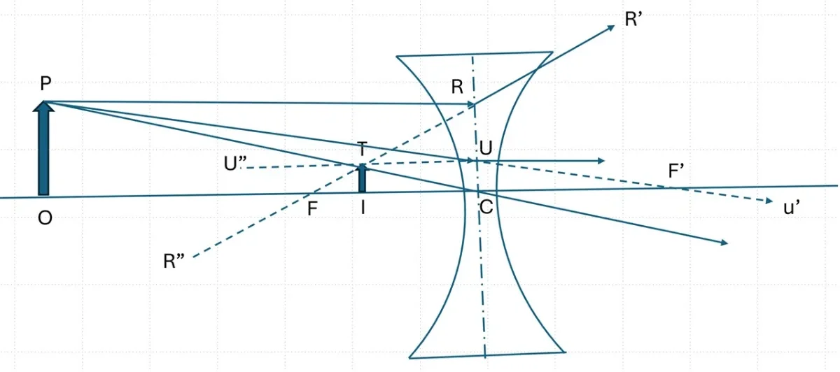
A concave lens spreads refracted rays outward, so their backward projections meet to form a virtual, upright, diminished image.
This simplified ray tracing diagram shows image formation by a concave lens. A ray from P travels parallel to the principal axis and refracts outward as if it came from the focal point F. A second ray travels toward F′ and emerges parallel to the principal axis. A third ray passes through the centre C of the lens and continues straight. The backward projections of the refracted rays meet at T, giving the tip of the virtual image, while I marks the image position on the principal axis.
Image Formed by a Diverging Lens
Object Position
Image Position
Image Nature
Common Use
Any real object position in front of the lens
Between the lens and the focal point on the object side
A real image is formed when actual light rays meet. Because real rays pass through the image position, the image can be projected onto a screen. This is why a projector can display an image on a wall and why a camera sensor can record an image.
A virtual image is formed when light rays do not actually meet, but appear to come from a point when traced backward. A virtual image cannot be projected directly onto a screen. However, it can still be seen by the eye because the eye receives diverging rays and interprets them as coming from a position behind the lens or mirror.
The word “virtual” does not mean fake or unimportant. A virtual image is visually real to the observer. It simply means the light rays do not physically pass through the apparent image position.
The Thin Lens Equation and Magnification Engine
For thin lenses, object distance, image distance, and focal length are related by the fundamental thin lens equation:
$$\frac{1}{f} = \frac{1}{u} + \frac{1}{v}$$
Here, f is the focal length, u is the object distance, and v is the image distance. This equation allows students to calculate where an image forms when the object distance and focal length are known.
Magnification
Linear magnification compares the physical height of the image with the physical height of the object:
$$m = \frac{h_i}{h_o} = \frac{v}{u}$$
Here, hi is the image height and ho is the object height. If the absolute magnitude of m is greater than 1, the image is enlarged. If it is less than 1, the image is diminished. In sign-convention-based treatments, a negative magnification value explicitly indicates that the image is inverted relative to the object.
Sign Convention and Careful Interpretation
Different textbooks sometimes use different sign conventions for lenses. This can confuse students if they memorise formulas without understanding the geometry. The safest approach is to combine calculation with ray-diagram reasoning.
In many standard school-level treatments (such as the “real-is-positive” convention), a converging lens has a positive focal length, while a diverging lens has a negative focal length. A real image usually has a positive image distance, while a virtual image is represented by a negative image distance, depending on the convention used.
Students should always check whether the final answer makes physical sense. For example, a diverging lens forming a real enlarged image from a single real object would be suspicious in a basic thin-lens setting. The ray diagram and the equation should support each other.
Rigorous Technical Worked Examples
Worked Example 1: Image Formed by a Converging Lens
Problem: An object is placed 30 cm in front of a converging lens with focal length 10 cm. Find the image distance.
Answer: The image is formed 15 cm on the other side of the lens. Since the object is placed beyond 2F (30 cm > 20 cm), the image is real, inverted, and diminished.
Worked Example 2: Magnification by a Converging Lens
Problem: An object of height 4 cm is placed 20 cm from a converging lens. The real image is formed 60 cm from the lens. Find the magnification and image height.
Solution:
Using the linear magnification formula:
$$m = \frac{v}{u}$$
$$m = \frac{60}{20} = 3$$
The image is three times the size of the object. Now solve for image height hi:
Answer: The image distance is -10 cm. The negative sign confirms a virtual image situated on the same side of the lens as the object. The image is upright and diminished.
Real-World Applications of Lenses
Lenses are not limited to classroom ray diagrams. They are central to many technologies that extend human sight, record images, support scientific discovery, and improve quality of life.
Cameras
A camera lens focuses light onto a sensor or film. By changing the lens position, aperture, and focal length, cameras control image sharpness, brightness, and field of view.
Projectors
Projectors use converging Lenses to form large real images on screens. The object inside the projector is usually placed between F and 2F so that the image is magnified.
Magnifying Glasses
A magnifying glass uses a converging lens with the object placed inside the focal length. The image appears virtual, upright, and enlarged.
Microscopes
Microscopes use combinations of lenses to magnify tiny objects. The objective lens first forms an enlarged image, and the eyepiece magnifies it further.
Telescopes
Telescopes collect light from distant objects and use lenses or mirrors to form images that reveal details too small or faint for the unaided eye.
Corrective Spectacles
Spectacles use converging or diverging lenses to correct how the eye focuses light, helping people with long-sightedness or short-sightedness see clearly.
Common Misconceptions about Lenses
Misconception 1: A Lens Always Magnifies
A lens does not always make an image bigger. A converging lens can form a diminished, same-size, or magnified image depending on where the object forms relative to the focal points. A diverging lens consistently projects a smaller, diminished image for real objects.
Misconception 2: A Virtual Image Is Not Real
A virtual image is not imaginary in the everyday sense. It can be seen clearly by the eye and photographed under suitable conditions. The term “virtual” means that the light rays only appear to come from the image position when projected backward, rather than physically crossing there.
Misconception 3: The Focal Point Is Always Where the Image Forms
The focal point is specifically where rays parallel to the principal axis meet. The true image placement coordinate changes dynamically based on object distance. Only objects located at an infinite distance form images perfectly on the focal plane.
Misconception 4: One Ray Is Enough to Locate an Image
A single ray shows one possible path of light, but it does not locate an image point by itself. At least two rays, or one ray plus geometric constraints, are mathematically required to find the intersection coordinate where the image point is formed.
Misconception 5: Thicker Lenses Always Give Better Images
A thicker lens bends light more sharply (higher dioptre power), but stronger bending does not mean a clearer image. Thick elements introduce significant geometric aberrations, distortion, and loss of light transmission. Advanced optical design relies on minimal, precise curvatures.
Quick Check: Common Misconceptions about Lenses
1. Does optical aberration always mean that a lens is broken or damaged?
A. Yes, aberration always means the lens is physically damaged.
B. No, aberration can arise naturally from lens shape, size, material, and optical geometry.
C. Yes, aberration only appears in old or dirty lenses.
D. No, aberration only happens in mirrors, not lenses.
Answer: B. Aberration does not mean a lens is broken. Even a flawless lens inherently introduces aberrations due to its spherical geometry and the refractive properties of glass materials.
2. If the centre of an image is sharp, does that guarantee that the whole image is sharp?
A. Yes, centre sharpness always means the whole image is sharp.
B. No, the edges may still show coma, astigmatism, field curvature, or distortion.
C. Yes, aberrations only affect the centre of the image.
D. No, but only colour can change at the edge.
Answer: B. A lens may form a sharp image near the centre while the edges remain less clear due to off-axis aberrations that multiply as the light path leaves the principal axis.
3. Do more lens elements always produce a better optical system?
A. Yes, the lens with the most elements is always best.
B. No, more elements can help correction but may also increase cost, weight, reflection losses, and alignment difficulty.
C. Yes, more elements remove all aberrations completely.
D. No, because lens elements have no effect on image quality.
Answer: B. More elements give designers parameters to control aberrations, but each element drops light throughput and increases physical scale, cost, and alignment tolerances.
4. Can software correction completely replace good optical design?
A. Yes, software can fully recover any optical detail after capture.
B. No, software can correct some defects, but it cannot fully recover information that was never sharply focused or recorded.
C. Yes, optical design is no longer needed in modern imaging.
D. No, software can only correct lens colour, not image geometry.
Answer: B. Software easily shifts distorted pixels back into position, but it cannot structurally recreate structural data lost to massive defocus blurs. Optical and digital systems must work in tandem.
5. Is a perfectly corrected image always the main goal of optical design?
A. Yes, every optical system must remove every imperfection.
B. No, optical systems are usually designed to be good enough for their purpose while balancing size, cost, brightness, sharpness, and usability.
C. Yes, small imperfections are never acceptable.
D. No, because optical design only concerns lens appearance.
Answer: B. Engineering is the art of constraint balancing. A consumer lens may allow minor edge defects to remain in exchange for being affordable, lightweight, and compact.
Review Questions and Answers
1. What is the main physical process that allows lenses to form images?
Answer: Lenses form images mainly through refraction. Light changes direction as it enters and leaves the lens material due to changes in its propagation velocity.
2. What is a converging lens?
Answer: A converging lens is an optical element that bends parallel incoming light rays inward toward a common focal point. It is physically thicker at the center than at its edges.
3. What is a diverging lens?
Answer: A diverging lens spreads parallel incoming light rays apart so that they appear to radiate out from a focal point on the incoming object side of the lens.
4. What is the difference between a real image and a virtual image?
Answer: A real image is formed where actual light rays physically intersect and can be projected onto a surface. A virtual image forms where rays only appear to meet when projected backward mathematically.
5. What happens to a ray passing through the optical centre of a thin lens?
Answer: In a thin-lens approximation, a ray passing through the optical centre exits without undergoing any noticeable spatial deviation or displacement.
6. What type of image does a diverging lens usually form for a real object?
Answer: It consistently forms a virtual, upright, and diminished image for any real object placement.
7. When does a converging lens act as a magnifying glass?
Answer: It acts as a magnifying glass specifically when the real object is placed inside the focal length (between the lens and the principal focus point).
8. Why can a real image be projected onto a screen?
Answer: Because physical photons pass directly through the coordinate space of a real image, allowing them to illuminate a material surface placed at that position.
9. What does focal length measure?
Answer: Focal length measures the physical distance from the lens’s optical centre to its principal focus point.
10. Why is a ray diagram useful even when calculations are available?
Answer: A ray diagram provides a visual reality check, helping students instantly spot algebraic sign errors or structural mismatches in their numerical calculations.
Thought-Provoking Questions with Answers
1. Why does a lens need curved surfaces rather than simply being a flat piece of glass?
Answer: A flat piece of glass causes uniform shifting but leaves parallel incoming rays parallel. Curved boundaries cause the angle of incidence to vary across the surface, ensuring different areas bend rays by varying amounts to gather them together.
2. Why does a magnifying glass produce a virtual image instead of projecting the image onto paper?
Answer: Within the focal length, rays diverge so rapidly upon entering the lens that they cannot cross on the far side. They continue spreading out, forcing our eye to track them backward to a large virtual intersection point behind the lens.
3. Why do camera lenses need focusing mechanisms?
Answer: The thin lens equation dictates that changing object distance u alters image distance v. A camera must physically move its glass elements relative to the fixed sensor to keep v perfectly aligned with the sensor plane.
4. Why are multiple lenses used in high-quality optical instruments?
Answer: Single elements suffer from natural dispersion and geometric rendering errors. Combining different structural shapes and materials allows one lens to systematically cancel out the specific optical aberrations of another.
5. Why is the eye often compared to a camera?
Answer: Both share the exact same structural topology: an outer adjustable lens system focuses an incoming light field onto an internal, highly light-sensitive array (the retina in the human eye, the pixel sensor in a digital camera).
Comprehensive Numerical Problems with Answers
Problem 1: A converging lens has a focal length of 20 cm. An object is placed 60 cm from the lens. Find the image distance.
Lenses form images by refracting light. A converging lens bends parallel rays toward a focal point, while a diverging lens spreads rays apart so that they appear to come from a focal point. By tracing rays from an object, students can locate the image and determine whether it is real or virtual, upright or inverted, magnified or diminished.
The thin lens equation connects ray diagrams with calculation, while magnification links image size with object size. Together, these ideas explain how cameras, projectors, magnifying glasses, spectacles, microscopes, telescopes, and the human eye use lenses to shape visual experience.
Reflection Question
If lenses form images by bending light, how might changing the shape, material, or arrangement of lenses change the way we see the world?