Prepare for University Studies & Career Advancement

Geometrical Optics

Geometrical optics, also known as ray optics, is a fundamental branch of optics that describes the behavior of light in terms of rays traveling in straight lines. It is based on the assumption that light propagates in linear paths until it encounters an optical surface, where it may undergo reflection or refraction. This approach simplifies the study of optical systems by focusing on image formation, lens behavior, and optical ray tracing without considering the wave properties of light, such as interference and diffraction. As a result, geometrical optics serves as a powerful tool for analyzing and designing optical components used in everyday life and scientific applications.

One of the core principles of geometrical optics is reflection, which describes how light bounces off surfaces following the law of reflection—the angle of incidence equals the angle of reflection. Mirrors and other reflective surfaces rely on this principle to form images, as seen in devices like periscopes, kaleidoscopes, and optical instruments. Another key concept is refraction, the bending of light as it passes from one medium to another due to a change in speed. Snell’s Law mathematically describes this phenomenon, which is essential in the function of lenses, prisms, and optical fibers. Refraction allows for the creation of magnifying glasses, corrective eyewear, and high-precision imaging systems.

A visually detailed representation of geometrical optics, illustrating light rays undergoing reflection, refraction, and dispersion through mirrors, lenses, and prisms.

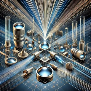
Geometrical optics is integral to the design and function of numerous optical devices. Lenses, which are widely used in microscopes, telescopes, and cameras, rely on refraction to focus or diverge light rays, enabling clear image formation. Prisms manipulate light by altering its direction or dispersing it into its constituent colors, a principle used in spectrometry and laser optics. Optical fibers, which are crucial for modern telecommunications, utilize total internal reflection to transmit light signals over long distances with minimal loss. The principles of ray optics are also applied in the development of complex imaging systems, from high-powered microscopes for biological research to astronomical telescopes that capture distant cosmic phenomena.

Despite its effectiveness, geometrical optics is limited in its ability to explain certain light behaviors, particularly wave-like phenomena such as diffraction and interference. For applications requiring precise light manipulation at very small scales, wave optics (physical optics) must be considered. However, for most practical optical systems involving lenses, mirrors, and fiber optics, geometrical optics remains a cornerstone of optical science and engineering. As technology advances, new materials and computational methods continue to refine optical system designs, making geometrical optics an essential field in scientific research, medical imaging, telecommunications, and emerging technologies.

Table of Contents

Key Concepts in Geometrical Optics

Reflection of Light

Reflection occurs when light bounces off the surface of a material.

Laws of Reflection:

  1. The incident ray, the reflected ray, and the normal all lie in the same plane.
  2. The angle of incidence () is equal to the angle of reflection (): θi=θr 

Types of Reflection:

  • Specular Reflection: Occurs on smooth, shiny surfaces (e.g., mirrors).
  • Diffuse Reflection: Occurs on rough surfaces, scattering light in many directions.

Refraction of Light

Refraction is the bending of light when it passes from one medium to another with a different refractive index.

Snell’s Law:

n1sinθ1=n2sinθ2n_1 \sin \theta_1 = n_2 \sin \theta_2 Refractive Index: n=cv Where c is the speed of light in a vacuum and and v is the speed of light in the medium.

Critical Angle and Total Internal Reflection:

If light moves from a denser to a rarer medium, it can be totally internally reflected if the angle of incidence exceeds the critical angle: sinθc=n2n1\sin \theta_c = \frac{n_2}{n_1}

Lenses and Image Formation

Lenses are transparent optical devices that refract light to form images.
  • Convex Lens (Converging): Focuses parallel light rays to a point.
  • Concave Lens (Diverging): Spreads parallel light rays apart.

Lens Formula:

1f=1v1u Where:
  • f is the focal length
  • v = image distance
  • u = object distance

Magnification:

M=hh=vu Magnification = height of the image / height of the object = image distance / object distance

Mirrors and Image Formation

Mirrors reflect light to form images. They are categorized into:
  • Plane Mirrors: Form virtual, upright, and laterally inverted images.
  • Concave Mirrors: Can form real or virtual images depending on the object’s position.
  • Convex Mirrors: Always form virtual, upright, and diminished images.

Mirror Equation:

1f=1v+1u\frac{1}{f} = \frac{1}{v} + \frac{1}{u} Sign Conventions:
  • Focal length (): Positive for concave, negative for convex mirrors.
  • object distance (u)
  • Image distance (v): Positive for real images, negative for virtual images.

Optical Instruments

Geometrical optics explains the functioning of various optical instruments:
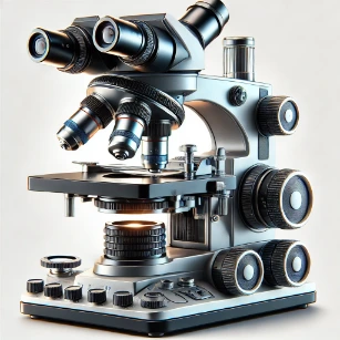
  • Microscopes: Use lenses to magnify small objects.
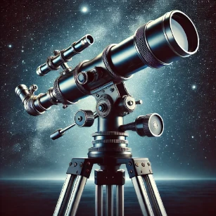
  • Telescopes: Magnify distant objects using a combination of lenses or mirrors.
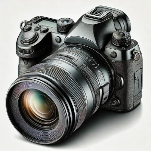
  • Cameras: Use lenses to focus light onto a photosensitive surface.
A Modern Compound Microscope
A Modern Compound Microscope – showcasing its optical components and precision design.
a modern astronomical telescope, mounted on a sturdy tripod with adjustment knobs and a finderscope, set against a starry night sky.
A Modern DSLR Camera with a zoom lens

Five Numerical Examples

Example 1: Image Formation by a Convex Lens

Problem: An object is placed 30 cm in front of a convex lens with a focal length of 10 cm. Find the image distance and magnification. Solution: Using the lens formula: 1f=1v1u\frac{1}{f} = \frac{1}{v} – \frac{1}{u} 110=1v130\frac{1}{10} = \frac{1}{v} – \frac{1}{30} 1v=110+130=430\frac{1}{v} = \frac{1}{10} + \frac{1}{30} = \frac{4}{30} v=304=7.5cmv = \frac{30}{4} = 7.5 \, \text{cm} Magnification: M=vu=7.530=0.25M = \frac{v}{u} = \frac{7.5}{-30} = -0.25 Answer: The image is virtual, inverted, and reduced with a magnification of -0.25, located 7.5 cm from the lens.

Example 2: Critical Angle for Glass-Air Interface

Problem: Find the critical angle for light traveling from glass () to air (). Solution: Using the critical angle formula: sinθc=n2n1=1.01.5=23\sin \theta_c = \frac{n_2}{n_1} = \frac{1.0}{1.5} = \frac{2}{3} θc=sin1(23)41.8\theta_c = \sin^{-1} \left( \frac{2}{3} \right) \approx 41.8^\circ Answer: The critical angle is approximately 41.8°.

Example 3: Image Formation by a Concave Mirror

Problem: An object is placed 20 cm in front of a concave mirror with a focal length of -10 cm. Find the image distance. Solution: Using the mirror formula: 1f=1v+1u\frac{1}{f} = \frac{1}{v} + \frac{1}{u} 110=1v+120\frac{1}{-10} = \frac{1}{v} + \frac{1}{20} 1v=110120=320\frac{1}{v} = \frac{1}{-10} – \frac{1}{20} = -\frac{3}{20} v=2036.67cmv = -\frac{20}{3} \approx -6.67 \, \text{cm} Answer: The image is virtual, upright, and located 6.67 cm behind the mirror.

Example 4: Refractive Index from Speed of Light

Problem: If light travels at 2×10⁸m/s2 \times 10^8 \, \text{m/s} in a medium, find the medium’s refractive index. Solution: n=cv=3×1082×108=1.5n = \frac{c}{v} = \frac{3 \times 10^8}{2 \times 10^8} = 1.5 Answer: The refractive index is 1.5.

Example 5: Magnification of a Microscope

Problem: A compound microscope has an objective lens of focal length 1 cm and an eyepiece of 5 cm. The object is placed 1.2 cm from the objective. Find the magnification. Solution: Using the lens formula for the objective: 1f=1v1u\frac{1}{f} = \frac{1}{v} – \frac{1}{u} 11=1v11.2\frac{1}{1} = \frac{1}{v} – \frac{1}{1.2} v6cmv \approx 6 \, \text{cm} Magnification: M=vu×25fe=61.2×255=5×5=25M = \frac{v}{u} \times \frac{25}{f_e} = \frac{6}{1.2} \times \frac{25}{5} = 5 \times 5 = 25 Answer: The total magnification is 25x.

Why Study Geometrical Optics

Ray Approximation and Light Propagation

Geometrical optics simplifies the study of light behavior by treating it as rays that travel in straight lines. Students use this approximation to analyze how light interacts with lenses, mirrors, and optical instruments. This framework enables the design of systems based on reflection and refraction. It offers foundational insight into the behavior of light before introducing more complex wave phenomena.

Image Formation and Optical Devices

Students study how lenses and mirrors produce images, including focal points, magnification, and image inversion. These principles are applied in microscopes, cameras, projectors, and telescopes. Understanding image formation enhances spatial reasoning and design thinking. It supports practical applications in photography, medical imaging, and astronomy.

Refraction, Reflection, and Dispersion

Key topics include Snell’s Law, critical angle, and prism dispersion. Students learn how different media affect light paths and how colors separate in refractive systems. These effects are central to visual perception and spectral analysis. They provide a concrete basis for advanced optics and spectroscopy.

Lens Systems and Aberrations

Students explore compound lens systems and how they can correct for optical distortions. Topics include spherical and chromatic aberrations and how to minimize them. These insights are vital for developing precise and high-resolution optical instruments. They bridge theoretical understanding with engineering practice.

Foundation for Advanced Optical Theory

Geometrical optics prepares students for wave optics, physical optics, and quantum optics. It supports early learning in optical design, engineering, and laser systems. The intuitive ray model builds confidence in visualizing light interactions. It lays a conceptual groundwork for diverse optical technologies.


Conclusion

Geometrical Optics provides a powerful framework for analyzing how light interacts with mirrors, lenses, and other optical devices. Its principles are foundational to many technologies in optics, engineering, medicine, and astronomy, making it an essential subject in physics and applied sciences.

Review Questions and Answers:

1. What is geometrical optics?
Answer: Geometrical optics is the study of light propagation in terms of rays. It simplifies the behavior of light by neglecting wave effects and focuses on reflection, refraction, and image formation through mirrors and lenses.

2. What is the law of reflection?
Answer: The law of reflection states that when a light ray strikes a surface, the angle of incidence is equal to the angle of reflection, with both angles measured from the normal to the surface.

3. How is Snell’s law used to describe refraction?
Answer: Snell’s law relates the angles of incidence and refraction to the refractive indices of two media by the equation

n1sinθ1=n2sinθ2n_1\sin\theta_1 = n_2\sin\theta_2

explaining how light bends when entering a different medium.

4. What is the focal point of a lens or mirror?
Answer: The focal point is the specific point where parallel rays of light converge (for a converging lens/mirror) or appear to diverge from (for a diverging lens/mirror) after reflection or refraction.

5. How do converging and diverging lenses differ in image formation?
Answer: Converging (convex) lenses bring parallel rays to a focus and can form real, inverted images, while diverging (concave) lenses spread rays apart, forming virtual, upright images.

6. What is the lens equation and how is it applied?
Answer: The lens equation

1f=1do+1di\frac{1}{f} = \frac{1}{d_o} + \frac{1}{d_i}

relates the focal length () of a lens to the object distance (dod_o) and the image distance (did_i). It is used to calculate the position and nature of the image formed by the lens.

7. How is magnification defined in geometrical optics?
Answer: Magnification () is defined as the ratio of the image height to the object height, and it can also be expressed as

m=didom = -\frac{d_i}{d_o}

for lenses and mirrors, where the negative sign indicates image inversion.

8. What are principal rays and why are they important in ray diagrams?
Answer: Principal rays are specific rays in an optical system used to construct ray diagrams. They include the ray parallel to the principal axis (which passes through the focal point after refraction) and the ray through the center of the lens (which travels in a straight line). They simplify the determination of image position and size.

9. How does the concept of refractive index affect light propagation?
Answer: The refractive index measures how much light slows down in a medium compared to vacuum. It affects the bending of light at interfaces and is critical in determining the behavior of lenses and optical components.

10. What are some common applications of geometrical optics in modern technology?
Answer: Geometrical optics is applied in the design of cameras, telescopes, microscopes, corrective eyeglasses, and laser systems. It also underpins optical fiber communication and various imaging devices used in medicine and industry.

Thought-Provoking Questions and Answers:

1. How does geometrical optics approximate light behavior, and what limitations does this approximation have?
Answer: Geometrical optics approximates light as rays that travel in straight lines and bend at interfaces according to simple laws. However, it neglects wave phenomena like interference, diffraction, and polarization, which become significant when the dimensions of optical elements are comparable to the wavelength of light.

2. How can the design of optical instruments benefit from an understanding of both geometrical and wave optics?
Answer: Combining geometrical optics for ray tracing and image formation with wave optics for resolving fine interference and diffraction effects leads to superior instrument design. This integrated approach enhances resolution, minimizes aberrations, and allows for the development of devices such as super-resolution microscopes and advanced telescopes.

3. In what ways does chromatic aberration impact optical systems, and how can it be corrected?
Answer: Chromatic aberration occurs because different wavelengths of light refract differently, causing color fringes and blurred images. It can be corrected using achromatic doublets or advanced lens coatings, which minimize wavelength-dependent focal shifts and improve image clarity.

4. How does the principle of total internal reflection in fiber optics rely on geometrical optics?
Answer: Total internal reflection occurs when light traveling in a medium with a higher refractive index hits the boundary with a lower refractive index at an angle greater than the critical angle, remaining confined within the medium. Geometrical optics principles, such as Snell’s law, are used to calculate the critical angle and design fiber-optic cables with minimal signal loss.

5. What are the implications of using aspheric lenses in optical systems compared to traditional spherical lenses?
Answer: Aspheric lenses are designed to minimize spherical aberrations by having non-spherical surfaces. They improve image quality and reduce the need for multiple lens elements, leading to more compact, efficient, and high-performance optical systems.

6. How might future innovations in optical materials influence the field of geometrical optics?
Answer: Innovations in optical materials, such as high-index glasses and nanostructured composites, can improve lens performance by reducing aberrations, enhancing light transmission, and enabling miniaturization. These advancements could lead to breakthroughs in imaging, communication, and optical computing.

7. How do principal ray diagrams help in understanding the formation of images by complex optical systems?
Answer: Principal ray diagrams simplify the analysis of image formation by tracing a few key rays that predict the position, size, and orientation of the image. They provide an intuitive method to design and troubleshoot optical systems, even in complex multi-element arrangements.

8. What challenges arise when integrating optical components into portable devices, and how can they be addressed?
Answer: Portable devices require miniaturized, robust, and energy-efficient optical components. Challenges include optical alignment, sensitivity to environmental factors, and limited space. Advances in micro-optics, integrated photonics, and flexible materials can address these issues, leading to improved performance and durability.

9. How can understanding the refractive properties of different media enhance the design of anti-reflective coatings?
Answer: Anti-reflective coatings are designed by tailoring the refractive index and thickness of thin films to minimize reflection through destructive interference. Knowledge of refractive properties allows for optimized coating designs that enhance light transmission in cameras, solar panels, and optical displays.

10. In what ways does geometrical optics contribute to the development of augmented and virtual reality systems?
Answer: Geometrical optics principles are essential in designing the optical systems used in AR/VR headsets, including lenses, waveguides, and displays. Accurate ray tracing ensures proper image projection, realistic depth perception, and minimal distortion, which are critical for immersive experiences.

11. How might the incorporation of adaptive optics revolutionize traditional geometrical optics in telescopes?
Answer: Adaptive optics uses deformable mirrors and real-time feedback to correct atmospheric distortions, greatly enhancing the resolution of ground-based telescopes. This technology allows for clearer, sharper images of celestial objects by dynamically adjusting the optical path.

12. What role do computational techniques play in modern optical design, and how do they complement traditional geometrical optics methods?
Answer: Computational techniques, such as ray-tracing software and optimization algorithms, enable the simulation and refinement of complex optical systems. They complement traditional methods by allowing designers to model aberrations, optimize lens shapes, and predict system performance, leading to more efficient and innovative optical designs.

Numerical Problems and Solutions:

1. A converging lens has a focal length of 12 cm. An object is placed 18 cm from the lens. Calculate the image distance using the lens formula.
Solution:
  Lens equation:

1f=1do+1di\frac{1}{f} = \frac{1}{d_o} + \frac{1}{d_i}

112=118+1di\frac{1}{12} = \frac{1}{18} + \frac{1}{d_i}

1di=112118=3236=136\frac{1}{d_i} = \frac{1}{12} – \frac{1}{18} = \frac{3 – 2}{36} = \frac{1}{36}

di=36cmd_i = 36 \, \text{cm}

2. Using the same lens, calculate the magnification of the image.
Solution:
  Magnification,

m=dido=3618=2m = -\frac{d_i}{d_o} = -\frac{36}{18} = -2

(Image is inverted and twice the size of the object).

3. A concave mirror has a radius of curvature of 30 cm. Determine its focal length.
Solution:  

f=R2=302=15cmf = \frac{R}{2} = \frac{30}{2} = 15 \, \text{cm}

4. In a mirror equation experiment, an object is placed 25 cm from a concave mirror and the image is formed at 16.67 cm from the mirror. Calculate the focal length of the mirror.
Solution:
  Mirror equation:

1f=1do+1di\frac{1}{f} = \frac{1}{d_o} + \frac{1}{d_i}

1f=125+116.670.04+0.06=0.10\frac{1}{f} = \frac{1}{25} + \frac{1}{16.67} \approx 0.04 + 0.06 = 0.10

f10cmf \approx 10 \, \text{cm}

5. A plane mirror reflects light such that the image distance equals the object distance. If an object is 40 cm in front of the mirror, what is the image distance?
Solution:
  For a plane mirror, the image distance equals the object distance, so the image is 40 cm behind the mirror.

6. In a ray diagram for a convex lens, an object 5 cm tall is placed 20 cm from a lens with a focal length of 10 cm. Determine the image height.
Solution:
  Lens equation:

110=120+1di\frac{1}{10} = \frac{1}{20} + \frac{1}{d_i}

1di=0.10.05=0.05\frac{1}{d_i} = 0.1 – 0.05 = 0.05

, so

di=20cmd_i = 20 \, \text{cm}

  Magnification,

m=dido=2020=1m = -\frac{d_i}{d_o} = -\frac{20}{20} = -1

  Image height =

m×object height=1×5cm=5cmm \times \text{object height} = -1 \times 5 \, \text{cm} = -5 \, \text{cm}

(Image is inverted and same size).

7. A prism with an apex angle of 60° is used to disperse light. If the deviation for red light is 20° and for blue light is 25°, calculate the angular separation between the two colors.
Solution:
  Angular separation =

25°20°=5°25° – 20° = 5°

8. A beam of light passes from air (n = 1.00) into water (n = 1.33) at an incidence angle of 40°. Calculate the refraction angle in water using Snell’s law.
Solution:
  Snell’s law:

n1sinθ1=n2sinθ2n_1 \sin \theta_1 = n_2 \sin \theta_2

1.00×sin(40°)=1.33×sinθ21.00 \times \sin(40°) = 1.33 \times \sin \theta_2

sinθ2=sin(40°)1.330.64281.330.483\sin \theta_2 = \frac{\sin(40°)}{1.33} \approx \frac{0.6428}{1.33} \approx 0.483

sin θ228.9°\theta_2 \approx 28.9°

9. A thin film of oil (n = 1.45) on water (n = 1.33) has a thickness of 500 nm. Calculate the optical path difference for light of wavelength 600 nm in air.
Solution:
  Optical path difference (OPD) =

2nt=2×1.45×500×109=1.45×10⁶m2n t = 2 \times 1.45 \times 500 \times 10^{-9} = 1.45 \times 10^{-6} \, \text{m}

  OPD in terms of wavelength =

1.45×106600×1092.42wavelengths\frac{1.45 \times 10^{-6}}{600 \times 10^{-9}} \approx 2.42

10. In a double-slit experiment, light of wavelength 700 nm produces fringes 4 mm apart on a screen 2 m away. Calculate the slit separation.
Solution:
  Fringe spacing

Δy=λLd\Delta y = \frac{\lambda L}{d}

d=λLΔy=700×109×24×103=1.4×1064×103=3.5×10⁴md = \frac{\lambda L}{\Delta y} = \frac{700 \times 10^{-9} \times 2}{4 \times 10^{-3}} = \frac{1.4 \times 10^{-6}}{4 \times 10^{-3}} = 3.5 \times 10^{-4} \, \text{m}

(0.35 mm).

11. A convex lens with a focal length of 25 cm forms an image of an object placed 40 cm from the lens. Determine the image distance using the lens formula.
Solution:  

1f=1do+1di\frac{1}{f} = \frac{1}{d_o} + \frac{1}{d_i}

10.25=10.40+1di\frac{1}{0.25} = \frac{1}{0.40} + \frac{1}{d_i}

4=2.5+1di4 = 2.5 + \frac{1}{d_i}

1di=42.5=1.5\frac{1}{d_i} = 4 – 2.5 = 1.5

di0.667md_i \approx 0.667 \, \text{m}

(66.7 cm).

12. A mirror produces a virtual image that is 30 cm from the mirror when an object is placed 20 cm in front. Using the mirror equation, verify the focal length of the mirror.
Solution:
  For a convex mirror, the mirror equation is

1f=1do+1di\frac{1}{f} = \frac{1}{d_o} + \frac{1}{d_i}

with proper sign conventions (using virtual image distances as negative).
  Assume

do=20cmd_o = 20 \, \text{cm}

(positive) and

di=30cmd_i = -30 \, \text{cm}

1f=120+130=0.050.0333=0.01667\frac{1}{f} = \frac{1}{20} + \frac{1}{-30} = 0.05 – 0.0333 = 0.01667

f60cmf \approx 60 \, \text{cm}

(Since for convex mirrors, the focal length is negative, we interpret the magnitude as 60 cm).