
Up to this point, physics mechanics treats moving objects as simple, structureless point-masses sliding along linear paths. But in the real world, objects have physical extensions, shapes, and distributions of matter. When you apply a force to an extended object—like pushing a door or turning a wrench—the outcome depends not just on how hard you push, but precisely where and at what angle you apply that force.
The Torque and Angular Momentum framework is the rotational twin of linear dynamics. It allows engineers to ensure massive bridges do not twist apart, guides aerospace researchers in stabilizing spinning satellites, and explains the bizarre, counter-intuitive behavior of gyroscopes. For an aspiring university student, mastering this transition from linear lines to rotational geometries is the ultimate bridge to advanced engineering and rigid-body dynamics.
Educational Pathway Note: This page introduces the vector mechanics of rotation, expanding upon linear kinematics to prepare you for multi-axis systems found in advanced engineering courses.
The Core Rotational Intuition (Without Calculus)
The Symmetry of Motion: Translational vs. Rotational Dynamics
To master rigid-body mechanics, you do not need to memorize an entirely new set of physical laws. Instead, you can look through the lens of structural symmetry. Every mathematical rule governing straight-line linear paths has a direct, parallel twin in the rotational domain. The table below outlines this complete translation system:
| Translational Parameter | Core Linear Equation | Rotational Equivalent | Core Rotational Equation | Interconnecting Vector Link |
|---|---|---|---|---|
| Linear Position | x | Angular Position | θ | s = θ · r |
| Linear Velocity | $$v = \frac{dx}{dt}$$ | Angular Velocity | $$\omega = \frac{d\theta}{dt}$$ | v = ω · r |
| Linear Acceleration | $$a = \frac{dv}{dt}$$ | Angular Acceleration | $$\alpha = \frac{d\omega}{dt}$$ | a_t = α · r |
| Mass (Inertia) | m | Moment of Inertia | $$I = \sum m_i r_i^2$$ | $$I = \int r^2 \, dm$$ |
| Force | $$F = m a$$ | Torque | $$\tau = I \alpha$$ | $$\vec{\tau} = \vec{r} \times \vec{F}$$ |
| Linear Momentum | $$p = m v$$ | Angular Momentum | $$L = I \omega$$ | $$\vec{\vec{L}} = \vec{r} \times \vec{p}$$ |
| Kinetic Energy | $$E_k = \frac{1}{2}m v^2$$ | Rotational Kinetic Energy | $$E_k = \frac{1}{2}I \omega^2$$ | $$E_{\text{total}} = E_{\text{trans}} + E_{\text{rot}}$$ |
Key Structural Insight: Notice the mathematical pattern of the vector interconnecting links column. To map any linear parameter into its corresponding rotational parameter, the system space takes the cross product or scalar multiplier of the radial position tracker vector ($\vec{r}$) against the active linear component.
What is the Mechanical Relationship Between Torque, Inertia, and Angular Momentum?
Torque represents the net twisting force applied to an object, while the moment of inertia measures its structural resistance to rotational acceleration based on mass distribution. Angular momentum tracks the total quantity of rotational motion conserved within a system over time.
Rotational mechanics is built on beautiful physical symmetries. Every concept you learned in linear motion has a direct, identical twin in the rotational world:
- Torque (τ): The rotational twin of force. While a net force causes an object to accelerate linearly, a net torque causes an object to change its rotational speed. Think of it as the “twisting effectiveness” of a force.
- Moment of Inertia (I): The rotational twin of mass. Mass measures an object’s resistance to changing its linear motion. Moment of Inertia measures how difficult it is to start or stop a rotating body. Crucially, I depends not just on how much mass an object has, but on how far away that mass is distributed from the pivot axis.
- Angular Momentum (L): The rotational twin of linear momentum. It tracks the rotational momentum account of a spinning body. In an isolated system, just like linear momentum, the total angular momentum account before an interaction must equal the total account after.
The Core Rotational Rule: An object’s twisting acceleration depends entirely on the leverage balance: Torque = (Lever Arm Distance) × (Force Perpendicular to the Lever).
Quick Check: Rotational Symmetries
Demystifying the Rotational Sign Convention
How Do You Determine the Direction of Torque and Angular Momentum Vectors?
Rotational vector directions are determined by the right-hand rule rather than linear trajectories. Curling the fingers of your right hand along the rotational path forces your extended thumb to point along the vector axis, defining counter-clockwise as positive and clockwise as negative.
In linear motion, tracking directions is simple: right is positive, left is negative. But how do you assign a direction vector to something spinning in a circle? Physics solves this using the Right-Hand Rule. Imagine curling the fingers of your right hand along the direction of the rotation; your extended thumb points in the true direction of the vector.
- Positive Torque / Angular Momentum (+): By standard convention, rotations that twist Counter-Clockwise (CCW) are positive. If you curl your right hand CCW, your thumb points straight up out of the page toward you.
- Negative Torque / Angular Momentum (-): Rotations that twist Clockwise (CW) are negative. Curling your right hand CW points your thumb straight down into the page away from you.
Quick Check: Rotational Directions
The Calculus Bridge (University Level)
What is the Vector Cross Product Definition of Torque?
Torque is mathematically defined as the cross product of the radial position vector and the applied force vector. This operation demands that the resulting torque vector always stands simultaneously perpendicular to both the force input and the displacement lever arm.
In foundational physics, torque is calculated as a simple scalar product: τ = rF\sin(θ). At the university level, this is upgraded to its true mathematical form: the vector cross product.
$$\vec{\tau} = \vec{r} \times \vec{F}$$Integrating the Moment of Inertia
For a single point mass, the moment of inertia is simple: I = mr^2. But if you are analyzing a continuous solid body—like a real engine flywheel, a cylindrical turbine, or a solid sphere—you cannot just add up individual points. You must break the continuous object into infinitely small mass elements (dm) and integrate them:
$$I = \int r^2 \, dm$$To compute this, you must transform the mass element into a spatial coordinate using the object’s volumetric density, denoted as ρ = dm/dV, allowing calculus to sum up the mass distribution geometrically.
Quick Check: Rotational Calculus Bridges
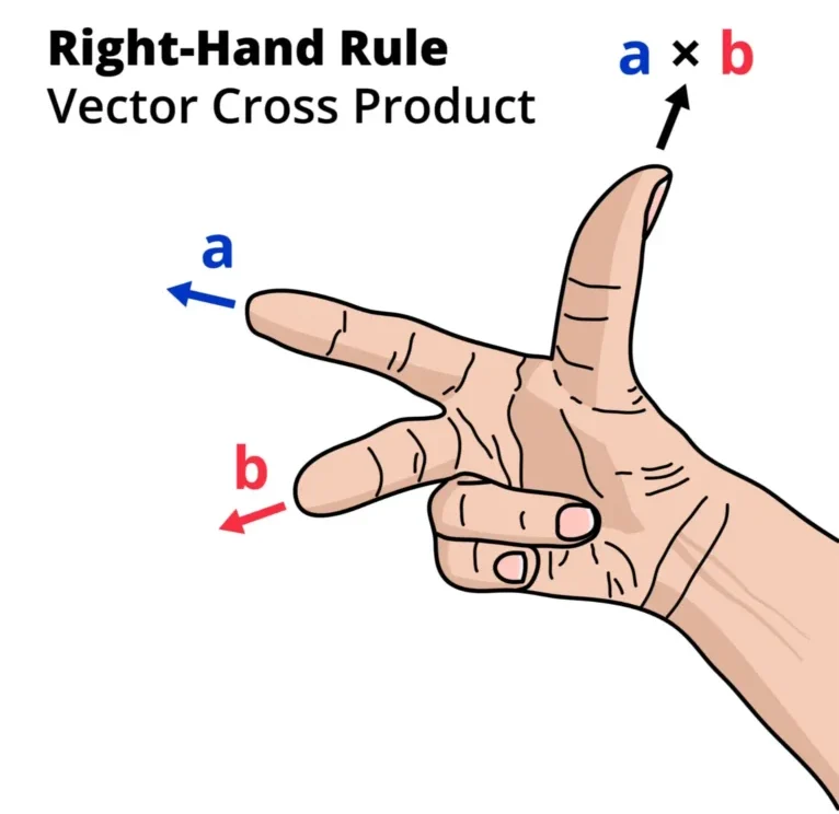
- The Flat Baseline Plane: Look at the flat plane formed by the position vector (r) extending from the pivot point to where the force is applied, and the force vector (F) pushing at an angle. These two lines define the two-dimensional workspace of the lever arm.
- The Perpendicular Torque Vector (τ): Notice that the resulting torque arrow points completely straight up along the vertical axis, forming a perfect 90° right angle to both individual baseline vectors. This visualizes the mathematical core of the cross product: the twisting effect doesn’t point along the line of the push, but rather along the central axis of the rotation it creates.
- The Right-Hand Rule Mechanics: If you align your right hand’s fingers pointing along the position vector r and curl them in the direction of the force vector F, your thumb is forced to point straight up along the path of the torque vector. If the force was reversed (pushing down), your thumb would point straight down, turning a positive counter-clockwise calculation into a negative clockwise coordinate.
Advanced Analytical Mechanics: The Matrix Formulation of Inertia
What Happens When an Object Rotates Asymmetrically in Three Dimensions?
In foundational physics, the moment of inertia is treated as a simple scalar number because rotation is restricted to a single fixed axis. However, true rigid bodies in three-dimensional space often experience asymmetrical mass distributions. To track how twisting forces couple across multiple axes simultaneously, the moment of inertia must be upgraded to a second-rank tensor, expressed mathematically as a symmetric 3×3 matrix.
1. Defining the Inertia Tensor Matrix
When an un-symmetrical rigid body rotates, an applied torque around the horizontal axis can actually trigger an acceleration or wobble around the vertical or depth axes. To mathematically map this cross-axis behavior, engineers use the Inertia Tensor, denoted as I. The matrix is organized as follows:
$$ \mathbf{I} = \begin{bmatrix} I_{xx} & I_{xy} & I_{xz} \\ I_{yx} & I_{yy} & I_{yz} \\ I_{zx} & I_{zy} & I_{zz} \end{bmatrix} $$The components of this matrix are divided into two distinct structural categories:
- Moments of Inertia (The Diagonal Elements): The terms Ixx, Iyy, and Izz represent the traditional resistances to rotation directly around the standard coordinate axes. For continuous bodies, they are evaluated using volumetric mass integrals: $$I_{xx} = \int (y^2 + z^2) \, dm$$ $$I_{yy} = \int (x^2 + z^2) \, dm$$ $$I_{zz} = \int (x^2 + y^2) \, dm$$
- Products of Inertia (The Off-Diagonal Elements): The terms with mixed coordinates (like Ixy, Ixz, and Iyz) measure the structural asymmetry of the mass distribution relative to the coordinate planes. Because the matrix is perfectly symmetric, Ixy = Iyx, Ixz = Izx, and Iyz = Izy. They are computed via: $$I_{xy} = -\int xy \, dm$$ $$I_{xz} = -\int xz \, dm$$ $$I_{yz} = -\int yz \, dm$$
2. The True Vector Relationship of Angular Momentum
Because mass resistance varies by direction, the system’s total angular momentum vector (L) does not always point in the exact same direction as the angular velocity vector (ω). Instead, the tensor matrix acts as a directional transformer:
$$ \begin{bmatrix} L_x \\ L_y \\ L_z \end{bmatrix} = \begin{bmatrix} I_{xx} & I_{xy} & I_{xz} \\ I_{yx} & I_{yy} & I_{yz} \\ I_{zx} & I_{zy} & I_{zz} \end{bmatrix} \begin{bmatrix} \omega_x \\ \omega_y \\ \omega_z \end{bmatrix} $$This directional misalignment is what causes high-speed machinery, uneven car tires, or tumbling satellites to experience intense wobbling stresses even if no external forces are pushing against them.
3. Principal Axes of Rotation
To eliminate these violent off-diagonal wobbling forces, engineers use matrix diagonalization. By calculating the eigenvalues of the inertia tensor matrix, you can rotate your coordinate reference frame until all cross-product terms drop completely to zero:
$$ \mathbf{I}_{\text{principal}} = \begin{bmatrix} I_1 & 0 & 0 \\ 0 & I_2 & 0 \\ 0 & 0 & I_3 \end{bmatrix} $$The resulting directions are called the Principal Axes of Rotation, and the values I1, I2, and I3 are the Principal Moments of Inertia. When a structure rotates cleanly around one of these specialized principal lines, its angular momentum vector aligns perfectly parallel with its angular velocity (&vec;L = I&vec;ω), guaranteeing completely stable, vibration-free high-speed rotation.
Engineering Case Study: The Vector Physics of Gyroscopic Precession
Why Do Spinning Rigid Wheels Move Perpendicularly to the Direction of an Applied Push?
When an external twisting force is applied to a stationary wheel, it simply tips over in the direction of the push. However, if that same wheel is spinning rapidly, it defies intuitive gravity by remaining upright and sweeping horizontally around its pivot support. This continuous, multi-axis sweeping motion is called gyroscopic precession, and its behavior is entirely governed by the vector cross-product tracking laws of angular momentum.
1. The Vector Derivation of Precessional Motion
Consider a high-speed flywheel spinning on a horizontal axle supported at only one end by a pivot node. Gravity acts directly on the wheel’s center of mass at a leverage distance vector r, pulling it downward with force vector Fg = mg.
This configuration sets up a horizontal torque vector (τ) acting directly at a 90° right angle to the axle plane:
$$\vec{\tau} = \vec{r} \times (m\vec{g})$$Because university-level mechanics defines torque as the time derivative of angular momentum, the net torque vector dictates the change in the system’s angular momentum vector (dL) over a small increment of time (dt):
$$\vec{\tau} = \frac{d\vec{L}}{dt}$$ $$d\vec{L} = \vec{\tau} \, dt$$Crucially, because the torque vector points horizontally and perfectly perpendicular to the flywheel’s massive internal spin angular momentum vector (L), the applied force cannot change the magnitude of the spinning motion. Instead, it forces the direction of the vector to rotate horizontally. The wheel sweeps around the central pivot in a circle rather than falling down toward the floor.
2. Calculating the Precession Frequency Formula
By tracking the horizontal angle change (dφ) of the sweeping axle over a time interval dt, we can derive the exact mathematical speed of this horizontal path, known as the precession angular frequency, denoted as Ω.
Using geometric arc-length approximations where dφ ≈ |dL| / |L|, the continuous precession equation simplifies to:
$$\Omega = \frac{d\phi}{dt} = \frac{\tau}{L}$$Substituting the explicit structural scalar parameters of gravitational torque (τ = mgr) and rigid-body spin momentum (L = Iω) isolates the standard engineering design formula:
$$\Omega = \frac{mgr}{I\omega}$$Crucial Operational Insight: This equation reveals a highly counter-intuitive relationship: the horizontal precessional sweeping speed (Ω) is inversely proportional to the speed of the flywheel (ω). If you slow down the primary internal wheel spin, the system sweeps horizontally much faster. Conversely, spinning the internal flywheel faster locks the axle tracking more firmly in space, minimizing precessional movement.
3. Real-World Flight Dynamics: Precession vs. Nutation
When engineers design stabilizing hardware for aircraft guidance computers or satellite platforms, they must separate gyroscopic behaviors into two distinct modes:
- Precession: The smooth, steady, and predictable horizontal circular transit around the pivot axis driven by continuous cross-axis torque fields.
- Nutation: A secondary, rapid “nodding” or bobbing vibration that causes the spinning axle to trace a wavy or looping path as it precesses. Nutation is a transient effect caused by sudden changes in external loads, friction spikes, or initial release conditions, and must be suppressed using mechanical dampers to maintain steady stabilization.
Real-World Applications
Aerospace Gyroscopic Stabilization
Satellites and high-altitude telescopes use internal, heavy reaction wheels spinning at thousands of RPM. Because these wheels possess massive angular momentum vectors, they resist external twisting disturbances from solar winds, maintaining alignment with perfect precision.Wind Turbine Structural Design
Engineers designing wind turbine blades must calculate the massive inertial resistance across blades stretching over 80 meters long. Because mass at the tips is far from the hub, it creates vast inertial loads, dictating motor torque parameters.High-Performance Flywheel Batteries
Modern clean energy grids store excess electricity by spinning heavy composite cylinders inside vacuum chambers. By maximizing the mass radius, they maximize rotational energy capacity, discharging power back to the grid by slowing down the flywheel.Common Misconceptions
Do Equal Mass Objects Always Twist with the Same Ease?
No, rotational resistance depends entirely on the spatial distribution of mass relative to the pivot, not weight alone. A hollow hoop places its mass at the outer boundary radius, creating far greater structural inertia than an identical mass solid sphere.
- The “Mass is Just Mass” Assumption: Students often believe that two objects of equal weight will rotate with identical ease. However, a 5 kg hollow hoop is significantly harder to spin than a 5 kg solid disc of the same radius. The hoop has all its mass pinned far to the edges, drastically increasing its moment of inertia.
- Confusing Angular and Tangential Velocity: A fly sitting at the outer rim of a spinning record player has a much higher linear speed (v) than a fly sitting near the center hub. However, their angular velocity (ω) is identical—both complete the exact same number of radians per second.
Practice Suite: End-of-Chapter Challenges
Apply your conceptual and analytical mechanics toolkits to these textbook-style challenges. Work through each problem independently before toggling the hidden solutions to audit your methodologies.
Category 1: Analytical & Conceptual Challenges
Category 2: Thought-Provoking Conceptual Challenges
Category 3: Numerical Examples of Illustrative Solutions
Theoretical Physics Foundations: Noether’s Theorem and Rotational Isotropy
Why is Angular Momentum Conserved Throughout the Universe?
In introductory physics, the Conservation of Angular Momentum is introduced as an empirical observation—something we verify through laboratory experiments with spinning wheels and figure skaters. However, advanced theoretical mechanics reveals a deeper truth: conservation laws are not arbitrary rules of nature. According to Noether’s Theorem, every fundamental conservation law is a direct mathematical consequence of a continuous geometric symmetry woven into the fabric of space and time.
1. The Core of Noether’s Theorem
Formulated by mathematician Emmy Noether, this theorem states that if a physical system behaves identically regardless of a specific continuous transformation, there must exist a corresponding physical quantity whose value remains perfectly static over time.
This deep mathematical link maps out three foundational symmetries in our universe:
- Time Translation Symmetry ⇒ Conservation of Energy: The laws of physics do not change from yesterday to today. This temporal consistency mathematically forces the total energy account of an isolated system to remain constant.
- Space Translation Symmetry ⇒ Conservation of Linear Momentum: The laws of physics are identical whether an experiment is performed in Paris, New York, or the Andromeda galaxy. This spatial uniformity forces linear momentum to be conserved.
- Rotational Isotropy of Space ⇒ Conservation of Angular Momentum: The fabric of space has no preferred directional bias. If you rotate an isolated experimental apparatus to face North, South, East, or West, the underlying laws of physics remain completely unchanged. This directional independence—known as isotropy—is the fundamental anchor that forces angular momentum to be perfectly conserved.
Advanced Analytical Mechanics: The Matrix Formulation of Inertia
What Happens When an Object Rotates Asymmetrically in Three Dimensions?
In foundational physics, the moment of inertia is treated as a simple scalar number because rotation is restricted to a single fixed axis. However, true rigid bodies in three-dimensional space often experience asymmetrical mass distributions. To track how twisting forces couple across multiple axes simultaneously, the moment of inertia must be upgraded to a second-rank tensor, expressed mathematically as a symmetric 3×3 matrix.
1. Defining the Inertia Tensor Matrix
When an un-symmetrical rigid body rotates, an applied torque around the horizontal axis can actually trigger an acceleration or wobble around the vertical or depth axes. To mathematically map this cross-axis behavior, engineers use the Inertia Tensor, denoted as I. The matrix is organized as follows:
$$ \mathbf{I} = \begin{bmatrix} I_{xx} & I_{xy} & I_{xz} \\ I_{yx} & I_{yy} & I_{yz} \\ I_{zx} & I_{zy} & I_{zz} \end{bmatrix} $$The components of this matrix are divided into two distinct structural categories:
- Moments of Inertia (The Diagonal Elements): The terms Ixx, Iyy, and Izz represent the traditional resistances to rotation directly around the standard coordinate axes. For continuous bodies, they are evaluated using volumetric mass integrals: $$I_{xx} = \int (y^2 + z^2) \, dm$$ $$I_{yy} = \int (x^2 + z^2) \, dm$$ $$I_{zz} = \int (x^2 + y^2) \, dm$$
- Products of Inertia (The Off-Diagonal Elements): The terms with mixed coordinates (like Ixy, Ixz, and Iyz) measure the structural asymmetry of the mass distribution relative to the coordinate planes. Because the matrix is perfectly symmetric, Ixy = Iyx, Ixz = Izx, and Iyz = Izy. They are computed via: $$I_{xy} = -\int xy \, dm$$ $$I_{xz} = -\int xz \, dm$$ $$I_{yz} = -\int yz \, dm$$
2. The True Vector Relationship of Angular Momentum
Because mass resistance varies by direction, the system’s total angular momentum vector (L) does not always point in the exact same direction as the angular velocity vector (ω). Instead, the tensor matrix acts as a directional transformer:
$$ \begin{bmatrix} L_x \\ L_y \\ L_z \end{bmatrix} = \begin{bmatrix} I_{xx} & I_{xy} & I_{xz} \\ I_{yx} & I_{yy} & I_{yz} \\ I_{zx} & I_{zy} & I_{zz} \end{bmatrix} \begin{bmatrix} \omega_x \\ \omega_y \\ \omega_z \end{bmatrix} $$This directional misalignment is what causes high-speed machinery, uneven car tires, or tumbling satellites to experience intense wobbling stresses even if no external forces are pushing against them.
3. Principal Axes of Rotation
To eliminate these violent off-diagonal wobbling forces, engineers use matrix diagonalization. By calculating the eigenvalues of the inertia tensor matrix, you can rotate your coordinate reference frame until all cross-product terms drop completely to zero:
$$ \mathbf{I}_{\text{principal}} = \begin{bmatrix} I_1 & 0 & 0 \\ 0 & I_2 & 0 \\ 0 & 0 & I_3 \end{bmatrix} $$The resulting directions are called the Principal Axes of Rotation, and the values I1, I2, and I3 are the Principal Moments of Inertia. When a structure rotates cleanly around one of these specialized principal lines, its angular momentum vector aligns perfectly parallel with its angular velocity (&vec;L = I&vec;ω), guaranteeing completely stable, vibration-free high-speed rotation.
Limits of the Classical Model
Classical rotational mechanics treats objects as perfectly rigid structures that experience zero deformation regardless of how fast they spin. In actual industrial environments, extreme centrifugal forces cause material stretching, demanding non-rigid elastic tensors. Furthermore, when analyzing subatomic particles like electrons, “spin” angular momentum is completely quantized into fixed values. At this scale, the electron is a structureless point particle with no physical radius, meaning it isn’t literally spinning mechanically—classical cross products break down entirely, yielding to quantum operator fields.
Rotational Terms Glossary
- Cross Product (Vector Product): A vector multiplication method operating on two vectors that yields a brand-new vector pointing completely perpendicular to the original plane.
- Angular Velocity (ω): The time rate of change of angular displacement, tracked systematically in radians per second.
- Conservation of Angular Momentum: The law stating that if the net external torque acting on a physical system is exactly zero, the total internal angular momentum vector remains perfectly static.
Navigating Classical Mechanics
Rotational dynamics requires a firm grasp of both translational motion laws and macroscopic system balances. Use our topic cluster to bridge the gap between point-mass mechanics and continuous physics.
Rotational & Extended Systems
Master cross-product rotational dynamics using Torque and Angular Momentum (Current Page), explore complex multi-axis rotating bodies in Rigid-Body Dynamics, and investigate non-accelerating torque balances within Statics.Translational Conservations
Study energy transaction metrics via Work, Energy, and Power, or examine structural collision matrices by reading about Linear Momentum and Collisions.The Principles of Motion
Review standard physical pathways through geometric Kinematics, inertia concepts in the First Law, net force functions in the Second Law, and vector pairings in the Third Law of Motion.Advanced Modern & Continuous Domains
Explore high-level university tracks including Lagrangian formulations in Analytical Mechanics, field equations in Continuum Mechanics, macroscopic flow in Fluid Mechanics, and cosmic speed limits in Relativistic Mechanics.Return to the high-level pillar hub: Classical Mechanics Core Guide.