
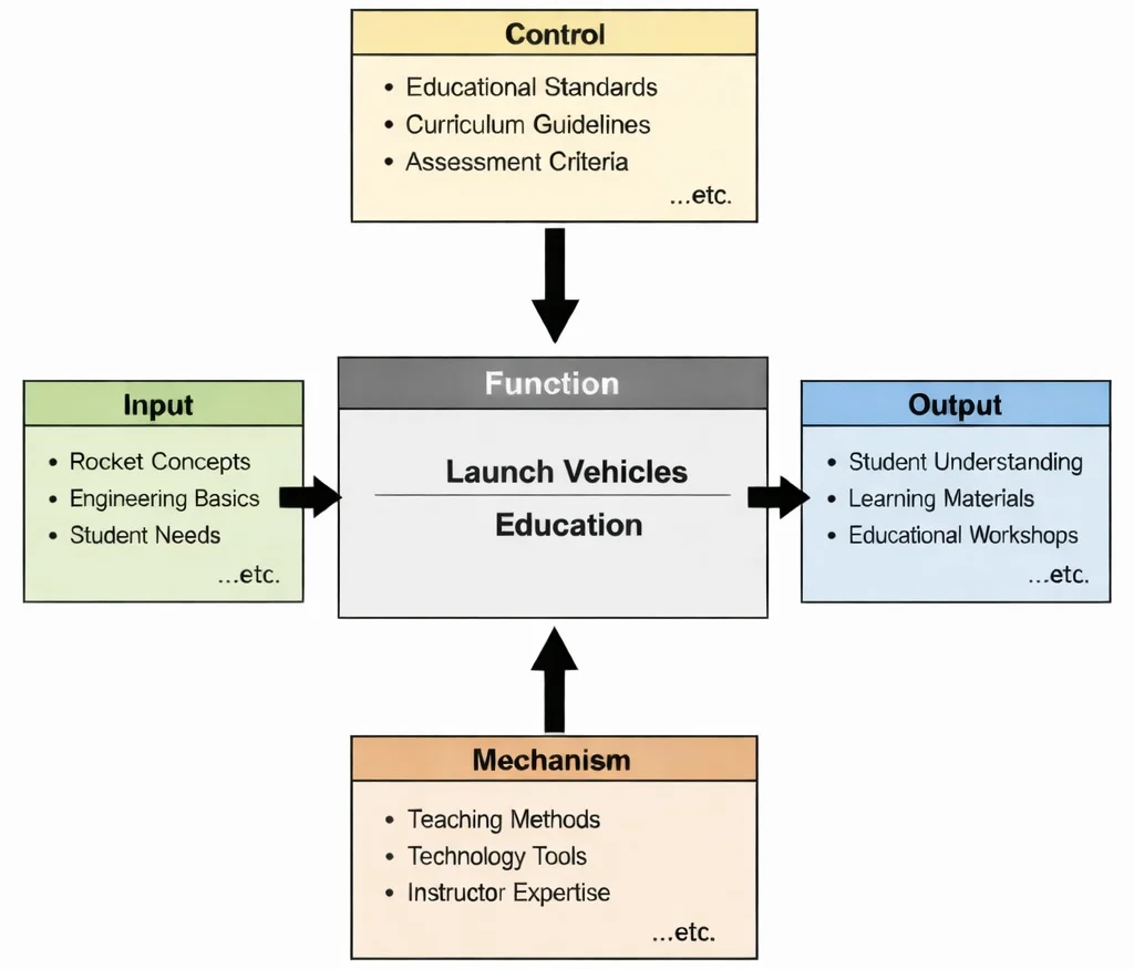
Launch vehicles education is, at its heart, the disciplined teaching of how engineered power becomes controlled ascent. In this IDEF0 functional framework, the learning process begins with core inputs: rocket propulsion principles, staging dynamics, aerodynamic drag parameters, and student diagnostic needs that determine instructional pacing and mathematical scaffolding. Governed by formal controls—aerospace engineering standards, flight safety corridors, orbital mechanics equations, and curriculum benchmarks—instruction remains grounded in physical realities. Supported by mechanisms such as trajectory simulation software, real-time telemetry calculators, and instructor expertise, learners develop systems-level engineering competencies: evaluating thrust-to-weight ratios, calculating multi-stage mass fractions via the Tsiolkovsky equation, analyzing aerodynamic stress under maximum dynamic pressure, and modeling orbital ascent trajectories.
Launch vehicles serve as the primary gateway to space, providing the immense kinetic energy and momentum transfer required to propel scientific payloads, commercial communications satellites, and crewed capsules beyond Earth's atmosphere. These complex machines represent the convergence of disciplines across STEM, integrating chemical propulsion thermodynamics, advanced materials science, high-speed fluid dynamics, and precise real-time guidance. Flight trajectory design demands rigorous mathematical optimization, supported by data science and analytics to simulate ascent corridors, model propellant consumption rates, and minimize gravity and atmospheric losses.
Modern rocket architectures are increasingly automated, relying on intelligent onboard avionics powered by artificial intelligence and machine learning. Algorithms employ supervised learning models for predictive engine component health monitoring and reinforcement learning to adapt flight control surfaces through severe wind shear. During hypersonic atmospheric exit and stage separation, computer vision systems process optical and infrared sensor feeds to confirm interstage jettison and guide autonomous retro-propulsive booster recovery on drone ships or ground landing pads.
Managing high-rate launch telemetry requires scalable digital infrastructure. Ground control segments utilize cloud computing platforms to run real-time hardware diagnostics and orbital insertion checks, while secure web and networking protocols distribute telemetry to international tracking networks. Furthermore, rocket engineering interfaces with quantum computing, where early research explores qubits, superposition, and quantum circuits for combinatorial trajectory design and complex molecular propellant modeling.
Launch operations are deeply integrated within the broader taxonomy of space exploration technologies and satellite systems. Advanced fabrication approaches in smart manufacturing and Industry 4.0—such as additive manufacturing of regeneratively cooled copper-alloy combustion chambers—shorten production cycles while reducing structural mass. Combined with embedded IoT smart sensors across ground service equipment, modern launch vehicles represent the cutting edge of aerospace systems engineering.

Mathematical & Propulsion Foundations of Launch Vehicles
Launch vehicle ascent is governed by Newton's laws of motion, compressible fluid dynamics, and variable-mass continuum mechanics. Unlike terrestrial vehicles that drive against a road or an ambient fluid, rockets accelerate via reactive momentum exchange in a vacuum, where trajectory profiles are governed by atmospheric pressure gradients, aerodynamic shear, and gravitational fields.
1. The Rocket Thrust Equation & Nozzle Pressure Expansion
A chemical rocket engine operates as a thermodynamic heat engine: chemical energy stored in molecular bonds is released via combustion in a high-pressure chamber (producing stagnation pressures pc up to 10–30 MPa and temperatures above 3,500 K). The hot gas accelerates through the sonic throat of a convergent-divergent de Laval nozzle, expanding supersonically to convert thermal enthalpy into directed kinetic energy. The total instantaneous thrust force Fthrust consists of momentum thrust and pressure thrust:
$$F_{\text{thrust}} = \dot{m} v_{\text{e}} + (p_{\text{e}} - p_{\text{a}}) A_{\text{e}}$$where:
- μ̇: Propellant mass flow rate (kg/s), representing oxidizer and fuel mass consumed per second (μ̇ = dm/dt).
- ve: Supersonic exhaust gas velocity at the nozzle exit plane (m/s).
- pe: Static pressure of the exhaust jet at the nozzle exit plane (Pa or N/m2).
- pa: Local ambient atmospheric pressure (Pa). At sea level, pa ≈ 101,325 Pa; in space, pa = 0 Pa.
- Ae: Geometric cross-sectional area of the nozzle exit bell (m2).
The term (pe − pa)Ae dictates expansion efficiency. When pe = pa, the nozzle is ideally expanded, maximizing net thrust. At sea level, if pe < pa, the nozzle is over-expanded, creating adverse pressure gradients that can separate boundary layers and generate destructive side-loads. In the vacuum of space (pa = 0), engines are permanently under-expanded (pe > 0), where widening the nozzle exit area Ae increases both ve and vacuum thrust.
Problem: A liquid rocket engine (modeled after a first-stage booster) operates with a constant propellant mass flow rate of μ̇ = 280.0 kg/s and an exit exhaust velocity of ve = 2,850.0 m/s. The nozzle exit bell has a diameter of d = 1.0 m (exit area Ae = π(0.5)2 ≈ 0.7854 m2) and an exit pressure of pe = 75,000.0 Pa (0.74 atm).
(a) Calculate the engine thrust at sea level (pa = 101,325.0 Pa).
(b) Calculate the engine thrust after climbing into the vacuum of space (pa = 0.0 Pa).
Engineering Conclusion: At sea level, the engine is over-expanded (pe < pa), so the ambient atmosphere pushes inward against the nozzle bell, reducing net thrust by 20.68 kN down to 777.32 kN. In space, atmospheric backpressure vanishes, and residual gas exit pressure adds 58.90 kN of pressure thrust, increasing total engine output to 856.90 kN (a 10.2% thrust increase with no extra propellant consumption).
2. Multi-Stage Staging Dynamics & The Serial Mass Fraction
To escape Earth's gravity well without exceeding structural limits, launch vehicles rely on serial staging. Discarding empty tanks and heavy sea-level engines sheds structural dry mass, allowing upper stages to accelerate from high initial velocity rather than from rest. For an N-stage vehicle, total achieved velocity increment Δvtotal is the sum of the velocity changes of each active stage:
$$\Delta v_{\text{total}} = \sum_{i=1}^{N} \Delta v_i = \sum_{i=1}^{N} I_{\text{sp}, i} g_0 \ln\left( \frac{m_{0, i}}{m_{\text{f}, i}} \right)$$For each stage i:
- Initial Wet Mass (m0, i): Includes stage i's structural dry mass, its propellant, all subsequent upper stages, and the payload: m0, i = mprop, i + mdry, i + m0, i+1.
- Burnout Mass (mf, i): The mass remaining immediately after stage i has burned its propellant, prior to separation: mf, i = m0, i − mprop, i = mdry, i + m0, i+1.
- Specific Impulse (Isp, i): Propellant efficiency of the stage engines (g0 = 9.80665 m/s2). Upper stages operate in vacuum and use high expansion ratio nozzles to achieve higher Isp than first stages.
Problem: A two-stage orbital rocket delivers a payload of mpayload = 4,500 kg into low Earth orbit. The launch vehicle specifications are:
• First Stage: Propellant mp1 = 380,000 kg, Dry structure md1 = 22,000 kg, Average Isp1 = 295.0 s.
• Second Stage: Propellant mp2 = 85,000 kg, Dry structure md2 = 4,500 kg, Vacuum Isp2 = 345.0 s.
Calculate the Δv delivered by each stage and determine if the vehicle exceeds the required 9,200.0 m/s threshold for orbital insertion.
Engineering Conclusion: Stage 1 provides 4,203.5 m/s, lifting the stack out of the atmosphere. Jettisoning the first stage allows Stage 2 to achieve a mass ratio of 10.44, delivering 7,937.5 m/s. The combined Δv of 12,141.0 m/s exceeds the 9,200.0 m/s orbital insertion requirement, providing ample margin to absorb atmospheric flight losses and reserve propellant for recovery burns.
3. Ascent Trajectory Losses (Δv Budget Accounting)
An orbital velocity of vcirc ≈ 7,800 m/s is required to maintain a circular low Earth orbit at h = 300 km. However, an actual rocket must generate significantly more velocity (Δvpropulsive ≈ 9,100–9,500 m/s) to overcome continuous environmental flight penalties. The total energy balance equation accounts for these components:
$$\Delta v_{\text{propulsive}} = v_{\text{orbit}} + \Delta v_{\text{gravity}} + \Delta v_{\text{drag}} + \Delta v_{\text{steering}} - v_{\text{Earth}}$$- Orbital Velocity (vorbit): The targeted kinetic orbital speed: vcirc = √(μ / (RE + h)).
- Gravity Losses (Δvgravity): Velocity lost to gravitational back-pull during ascent: ∫ g(h) sin(γ) dt, where γ is the flight path angle relative to the local horizontal. A vertical climb (γ = 90°) loses 9.8 m/s of velocity every second. Initiating a gravity turn tilts the thrust vector toward horizontal (γ → 0°) to minimize this loss.
- Aerodynamic Drag Losses (Δvdrag): Energy dissipated overcoming atmospheric drag: ∫ [D / m(t)] dt, where drag D = 0.5 ρ(h) v2 Cd A. Drag is concentrated below 30 km altitude, peaking around Max Q.
- Steering & Backpressure Losses (Δvsteering): Minor thrust vector gimbal offsets and sea-level nozzle backpressure penalties (100–200 m/s).
- Earth Rotation Assist (vEarth): Free tangential launch speed provided by Earth's eastward rotation: vEarth = ωE RE cos(φ), where ωE ≈ 7.2921 × 10⁻⁵ rad/s, RE ≈ 6,378 km, and φ is launch site latitude.
Problem: A launch vehicle departs eastward from the Kennedy Space Center (Cape Canaveral, latitude φ = 28.5° N) targeting an orbit at altitude h = 300.0 km (μ = 398,600.4 km3/s2, RE = 6,371.0 km). Flight telemetry records:
• Total burn time across both stages: tburn = 480.0 s with an average effective gravity loss angle such that Δvgravity = 1,220.0 m/s.
• Total integrated aerodynamic drag penalty: Δvdrag = 145.0 m/s.
• Gimbal thrust steering and nozzle backpressure penalties: Δvsteering = 85.0 m/s.
Calculate the required circular orbital velocity vorbit, the Earth rotation assist vEarth, and the total required propulsive Δvpropulsive the rocket engines must deliver.
Engineering Conclusion: Reaching orbit requires achieving a circular velocity of 7,730.0 m/s. Flight losses add 1,450.0 m/s in gravity, drag, and steering penalties, but launching eastward from Florida provides a 408.7 m/s rotation assist. The vehicle's propulsion system must deliver a total velocity increment of 8,771.3 m/s.
Classification & Performance of Modern Launch Vehicles
Aerospace agencies classify launch vehicles based on useful payload mass capacity delivered to Low Earth Orbit (LEO, 200–400 km altitude):
| Vehicle Class | LEO Payload Capacity | Representative Systems | Primary Mission Application |
|---|---|---|---|
| Small-Lift | < 2,000 kg | Rocket Lab Electron, Vega-C | Dedicated CubeSat constellations, rapid-response tactical space access. |
| Medium-Lift | 2,000 – 20,000 kg | Soyuz-2, Atlas V, Vulcan Centaur | Earth-observation satellites, GPS navigation rings, space station cargo resupply. |
| Heavy-Lift | 20,000 – 50,000 kg | Falcon 9, Ariane 64, Proton-M | Geostationary communications satellites, crewed orbital spacecraft (Crew Dragon). |
| Super-Heavy-Lift | > 50,000 kg | NASA SLS, Falcon Heavy, Starship | Crewed lunar missions (Artemis), Mars base equipment, deep-space planetary telescopes. |
Interactive Rocket Staging & Ideal Rocket Equation (Δv) Calculator
Adjust specific impulse (Isp), initial wet mass (m0), and burnout dry mass (mf) to compute effective exhaust velocity and total velocity increment (Δv):
Why Study Launch Vehicles
1. Mastering Advanced Propulsion & Thermodynamics
Launch vehicles push fluid mechanics and combustion chemistry to physical extremes. Students examine turbopump fluid machinery operating at tens of thousands of RPM, regenerative cryogenic cooling channels, and high-expansion supersonic nozzles, preparing them for advanced aerospace and industrial thermofluid engineering.
2. The Economics of Reusability & Commercial Spaceflight
Developing vertically landing reusable rockets has lowered the cost of space transportation by more than 70%. Learning how retro-propulsion, grid fins, and automated relight algorithms operate provides students with insights into how modern commercial aerospace firms transform industrial business models.
3. Cross-Disciplinary Avionics and Closed-Loop Control
Guiding a slender, flexible launch vehicle through supersonic aerodynamic turbulence requires real-time Kalman filtering, inertial measurement units (IMUs), and hydraulic engine gimbal control. These control theory principles apply directly to robotics, autonomous electric vehicles, and industrial automation.
Frequently Asked Questions on Launch Vehicles
1. Why is chemical propulsion still the dominant technology for launch vehicles?
Ascending from Earth requires an engine thrust-to-weight ratio (T/W) significantly greater than 1.0 (typically 1.2–1.5 at liftoff) to overcome gravitational acceleration. While electric ion thrusters have high specific impulses (> 3,000 s), their thrust is measured in millinewtons, which cannot overcome Earth's surface gravity. Chemical combustion remains the only operational technology capable of releasing the millions of Newtons of thrust needed to accelerate heavy vehicles out of the atmosphere.
2. What is Max Q and why is it a critical phase of flight?
Max Q (maximum dynamic pressure) is the point during ascent where aerodynamic stress on the vehicle structure reaches its peak (q = ½ρv2). As the rocket accelerates, velocity v increases, but atmospheric density ρ decreases with altitude. The product peaks at roughly 10–15 km altitude. Engines are throttled down prior to Max Q to reduce mechanical shear loads on propellant tanks and fairings before throttling back to full power in the upper atmosphere.
3. What are the key differences between LOX/RP-1 and LOX/Methane propellants?
RP-1 (refined kerosene) is dense, allowing compact tanks and high liftoff thrust, but leaves carbon soot deposits that complicate engine reuse. Liquid methane (CH4) has a higher specific impulse (∼ 380 s vacuum vs. ∼ 348 s for RP-1) and burns clean with minimal coking, enabling rapid engine reuse with less refurbishment. Methane can also be synthesized on Mars via the Sabatier reaction, supporting in-situ return propellant production.
Comprehensive Launch Vehicles Practice Suite
Part A: Core Knowledge & Foundational Concepts
1. Explain why launch vehicles discard spent stages during ascent.
2. Compare liquid-propellant rocket engines with solid rocket motors.
3. What role do grid fins and cold-gas thrusters play in booster recovery?
Part B: Strategic & Mission Engineering Analysis
1. How does booster reusability alter rocket structural and propellant mass fractions?
2. Why is orbital refueling critical for super-heavy interplanetary architectures?
Part C: Step-by-Step Quantitative Engineering Problems
Problem 1: Uniform Acceleration and Distance Travelled
Scenario: A launch vehicle accelerates uniformly from rest to an injection speed of v = 8,000.0 m/s over t = 150.0 seconds of constant acceleration. Compute average acceleration a and distance travelled s.
Step-by-Step Derivation:
$$ \begin{aligned} a &= \frac{v}{t} = \frac{8{,}000.0 \text{ m/s}}{150.0 \text{ s}} \approx 53.333 \text{ m/s}^2 \\ s &= \frac{1}{2} a t^2 = 0.5 \times 53.333 \text{ m/s}^2 \times (150.0 \text{ s})^2 \\ s &= 0.5 \times 53.333 \times 22{,}500 \approx 600{,}000.0 \text{ m} = 600.0 \text{ km} \end{aligned} $$Answer & Conclusion: Average acceleration is 53.33 m/s², covering a distance of 600.0 km.
Problem 2: First-Stage Burn Mass Breakdown and Propellant Fraction
Scenario: A rocket has a liftoff mass of m0 = 400,000.0 kg. The first stage burns mprop = 350,000.0 kg of propellant. Calculate the remaining vehicle mass and the first-stage propellant mass fraction.
Step-by-Step Derivation:
$$ \begin{aligned} m_{\text{rem}} &= m_0 - m_{\text{prop}} = 400{,}000.0 \text{ kg} - 350{,}000.0 \text{ kg} = 50{,}000.0 \text{ kg} \\ \text{Fraction} &= \frac{m_{\text{prop}}}{m_0} = \frac{350{,}000.0 \text{ kg}}{400{,}000.0 \text{ kg}} = 0.875 = 87.5\% \end{aligned} $$Answer & Conclusion: The remaining vehicle mass is 50,000.0 kg and the propellant mass fraction is 87.5%.
Problem 3: Engine Specific Impulse and Propellant Mass Flow Rate
Scenario: A rocket engine operates with a specific impulse of Isp = 300.0 s. Compute its effective exhaust velocity ve, and determine the propellant mass flow rate μ̇ required to generate a thrust of F = 5.0 × 10⁶ N (using g0 = 9.81 m/s2).
Step-by-Step Derivation:
$$ \begin{aligned} v_{\text{e}} &= I_{\text{sp}} \times g_0 = 300.0 \text{ s} \times 9.81 \text{ m/s}^2 = 2{,}943.0 \text{ m/s} \\ \dot{m} &= \frac{F}{v_{\text{e}}} = \frac{5{,}000{,}000.0 \text{ N}}{2{,}943.0 \text{ m/s}} \approx 1{,}698.95 \text{ kg/s} \end{aligned} $$Answer & Conclusion: Exhaust velocity is 2,943.0 m/s and mass flow rate is approximately 1,698.95 kg/s.
Problem 4: Constant Acceleration Flight Distance and Velocity
Scenario: A vehicle undergoes constant acceleration of a = 60.0 m/s2 for a burn time of t = 120.0 seconds. Calculate final burnout velocity v and distance traversed s.
Step-by-Step Derivation:
$$ \begin{aligned} v &= a \times t = 60.0 \text{ m/s}^2 \times 120.0 \text{ s} = 7{,}200.0 \text{ m/s} \\ s &= \frac{1}{2} a t^2 = 0.5 \times 60.0 \text{ m/s}^2 \times (120.0 \text{ s})^2 \\ s &= 30.0 \times 14{,}400 = 432{,}000.0 \text{ m} = 432.0 \text{ km} \end{aligned} $$Answer & Conclusion: Final velocity is 7,200.0 m/s and total distance covered is 432.0 km.
Problem 5: Circular Low Earth Orbit Speed and Radius
Scenario: A satellite is inserted into a circular orbit at altitude h = 400.0 km. Given Earth's radius RE = 6,371.0 km and gravitational parameter μ = 3.986 × 10¹⁴ m3/s2, compute orbital radius r and orbital velocity v.
Step-by-Step Derivation:
$$ \begin{aligned} r &= R_{\text{E}} + h = 6{,}371.0 \text{ km} + 400.0 \text{ km} = 6{,}771.0 \text{ km} = 6.771 \times 10^6 \text{ m} \\ v &= \sqrt{\frac{\mu}{r}} = \sqrt{\frac{3.986 \times 10^{14} \text{ m}^3/\text{s}^2}{6.771 \times 10^6 \text{ m}}} \approx \sqrt{58{,}868{,}704.8} \approx 7{,}672.6 \text{ m/s} \end{aligned} $$Answer & Conclusion: Orbital radius is 6,771.0 km and circular speed is approximately 7,673 m/s (7.67 km/s).
Problem 6: Two-Stage Velocity Allocation & Percentage Contribution
Scenario: A two-stage launch vehicle provides Δv1 = 6,000.0 m/s from its first stage and Δv2 = 4,000.0 m/s from its second stage. Calculate total velocity increment and percentage contribution from each stage.
Step-by-Step Derivation:
$$ \begin{aligned} \Delta v_{\text{total}} &= \Delta v_1 + \Delta v_2 = 6{,}000.0 \text{ m/s} + 4{,}000.0 \text{ m/s} = 10{,}000.0 \text{ m/s} \\ \%_{\text{Stage 1}} &= \left( \frac{6{,}000.0}{10{,}000.0} \right) \times 100 = 60.0\% \\ \%_{\text{Stage 2}} &= \left( \frac{4{,}000.0}{10{,}000.0} \right) \times 100 = 40.0\% \end{aligned} $$Answer & Conclusion: Total Δv is 10,000.0 m/s, with Stage 1 providing 60.0% and Stage 2 providing 40.0%.
Problem 7: Steady-State Burn Mass Consumption and Burn Fraction
Scenario: An engine burns fuel at μ̇ = 500.0 kg/s for t = 180.0 seconds. For an initial vehicle mass of m0 = 600,000.0 kg, compute total fuel mass burned and the fuel mass fraction.
Step-by-Step Derivation:
$$ \begin{aligned} m_{\text{fuel}} &= \dot{m} \times t = 500.0 \text{ kg/s} \times 180.0 \text{ s} = 90{,}000.0 \text{ kg} \\ \text{Fraction} &= \frac{m_{\text{fuel}}}{m_0} = \frac{90{,}000.0 \text{ kg}}{600{,}000.0 \text{ kg}} = 0.15 = 15.0\% \end{aligned} $$Answer & Conclusion: Total fuel consumed is 90,000.0 kg, representing a fuel fraction of 15.0%.
Problem 8: Engine Thrust from Exhaust Velocity and Flow Rate
Scenario: A rocket engine operates with a specific impulse of Isp = 320.0 s and mass flow rate μ̇ = 1,200.0 kg/s. Compute effective exhaust velocity ve and total generated thrust F (using g0 = 9.81 m/s2).
Step-by-Step Derivation:
$$ \begin{aligned} v_{\text{e}} &= I_{\text{sp}} \times g_0 = 320.0 \text{ s} \times 9.81 \text{ m/s}^2 = 3{,}139.2 \text{ m/s} \\ F &= \dot{m} \times v_{\text{e}} = 1{,}200.0 \text{ kg/s} \times 3{,}139.2 \text{ m/s} \\ F &= 3{,}767{,}040.0 \text{ N} = 3.767 \text{ MN} \end{aligned} $$Answer & Conclusion: Exhaust velocity is 3,139.2 m/s and total thrust generated is approximately 3.77 MN.
Problem 9: Propellant Depletion and Percentage Mass Reduction
Scenario: A heavy rocket with liftoff mass m0 = 1,000,000.0 kg burns mprop = 560,000.0 kg of propellant. Calculate final burnout mass mf and percentage mass reduction.
Step-by-Step Derivation:
$$ \begin{aligned} m_{\text{f}} &= m_0 - m_{\text{prop}} = 1{,}000{,}000.0 \text{ kg} - 560{,}000.0 \text{ kg} = 440{,}000.0 \text{ kg} \\ \%\text{ Reduction} &= \left( \frac{560{,}000.0}{1{,}000{,}000.0} \right) \times 100 = 56.0\% \end{aligned} $$Answer & Conclusion: Final burnout mass is 440,000.0 kg, representing a 56.0% mass reduction.
Problem 10: Tsiolkovsky Equation Required Mass Ratio Calculation
Scenario: A mission profile requires a total velocity change of Δv = 9,500.0 m/s. For an effective exhaust velocity of ve = 3,000.0 m/s, compute the required mass ratio m0 / mf.
Step-by-Step Derivation:
$$ \begin{aligned} \Delta v &= v_{\text{e}} \ln\left( \frac{m_0}{m_{\text{f}}} \right) \Rightarrow \frac{\Delta v}{v_{\text{e}}} = \frac{9{,}500.0 \text{ m/s}}{3{,}000.0 \text{ m/s}} \approx 3.16667 \\ \frac{m_0}{m_{\text{f}}} &= e^{3.16667} \approx 23.728 \end{aligned} $$Answer & Conclusion: The required vehicle mass ratio m0 / mf is approximately 23.73.
Problem 11: Total Impulse and Propellant Mass Expelled
Scenario: A rocket stage produces a constant thrust of F = 4.5 × 10⁶ N for t = 90.0 seconds. Calculate total impulse J delivered, and determine propellant mass expelled if exhaust velocity is ve = 3,400.0 m/s.
Step-by-Step Derivation:
$$ \begin{aligned} J &= F \times t = 4{,}500{,}000.0 \text{ N} \times 90.0 \text{ s} = 405{,}000{,}000.0 \text{ N}\cdot\text{s} = 4.05 \times 10^8 \text{ N}\cdot\text{s} \\ m_{\text{prop}} &= \frac{J}{v_{\text{e}}} = \frac{4.05 \times 10^8 \text{ N}\cdot\text{s}}{3{,}400.0 \text{ m/s}} \approx 119{,}117.65 \text{ kg} \end{aligned} $$Answer & Conclusion: Total impulse is 4.05 × 10⁸ N·s and expelled propellant mass is approximately 119,118 kg.
Problem 12: High-Energy Mission Stage Velocity Allocation
Scenario: An interplanetary mission requires a total Δv of 12,000.0 m/s. If the lower stage delivers Δv1 = 7,000.0 m/s, calculate required second-stage velocity Δv2 and the percentage allocation between stages.
Step-by-Step Derivation:
$$ \begin{aligned} \Delta v_2 &= \Delta v_{\text{total}} - \Delta v_1 = 12{,}000.0 \text{ m/s} - 7{,}000.0 \text{ m/s} = 5{,}000.0 \text{ m/s} \\ \%_{\text{Stage 1}} &= \left( \frac{7{,}000.0}{12{,}000.0} \right) \times 100 \approx 58.33\% \\ \%_{\text{Stage 2}} &= \left( \frac{5{,}000.0}{12{,}000.0} \right) \times 100 \approx 41.67\% \end{aligned} $$Answer & Conclusion: Second stage must deliver 5,000.0 m/s, with Stage 1 providing 58.33% and Stage 2 providing 41.67%.
Launch Vehicles: Summary & Learning Wrap-Up
Launch vehicles represent the technological foundation of space exploration, converting chemical propellant energy into targeted orbital momentum. By balancing the mathematical constraints of the Tsiolkovsky rocket equation, optimizing multi-stage mass ratios, and mitigating dynamic pressure during atmospheric exit, aerospace engineers deliver critical payloads to orbit. As reusability and green propellants continue to lower launch costs, mastering these rocketry principles prepares students to contribute to satellite constellations, deep-space probes, and permanent human infrastructure beyond Earth.