Prepare for University Studies & Career Advancement
Thin-Film Interference
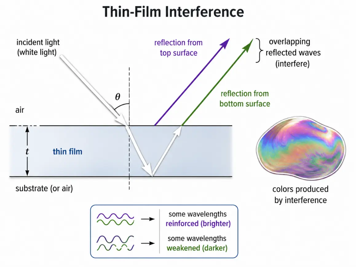
Thin-film interference is the wave effect that produces bright colours in soap bubbles, oil films, anti-reflection coatings, and very thin transparent layers. It happens when light reflects from both the top and bottom surfaces of a thin film, and the reflected waves overlap with each other.
At first glance, the colours in a soap bubble may look like a simple surface colour. In reality, they are not fixed pigments. They are produced by interference. Some wavelengths are strengthened, while others are weakened, depending on film thickness, refractive index, viewing angle, and phase changes during reflection.
This makes thin-film interference an important topic in Light and Optics. It connects reflection, refraction, wavelength, path difference, phase change, and colour. It also shows how a very small difference in distance, often comparable to the wavelength of visible light, can create a visible optical effect.
This page belongs to the Wave Optics cluster, which functions as a structural core inside the broader field of physical science. It builds naturally from Interference of Light and prepares students to understand optical coatings, Newton’s rings, wedge films, and the use of interference in measurement and technology.
Explore the Wave Optics Cluster
Thin-film interference is best studied alongside the other core wave behaviors of light. You can explore the complete pathway through the following subpages:
Explains how the electric field direction of light can be selected, rotated, analysed, or modified by materials and surfaces.
Thin-film interference occurs when light reflected from the top and bottom surfaces of a thin layer overlaps, causing some wavelengths to be reinforced and others to be weakened.
The Evolutionary Path: History, System Barriers, and Foundry Paradigms
The progression of thin-film mechanics from an interesting natural observation into a foundational manufacturing standard changed semiconductor engineering and precision instrument processing.
The Historical Journey
The study of thin-film reflections began in 1665 when Robert Hooke and Isaac Newton independently documented the colorful iridescence of thin flakes of mica and soap bubble membranes. In 1801, Thomas Young used his principle of wave interference to solve the physical math underlying Hooke’s observations, proving that the colors come from path differences. By 1818, Augustin-Jean Fresnel tracked the phase behavior of light at boundary surfaces, creating the foundational mathematical expressions that dictate reflection parameters. The industrial applications took off in 1935 when Alexander Smakula developed the first anti-reflection lens coatings inside the Carl Zeiss foundries, shifting thin-film optics into an essential commercial industry.
Contemporary Technical Hurdles
The primary bottleneck inside modern multi-layer coating systems is managing layer uniformity and surface roughness profiles. When processing high-performance filters, materials are deposited using chemical vapor systems to build stacks that are dozens of layers deep. If a single film layer displays a thickness variation of even 0.5 nm across the crystal substrate, the target constructive path alignments fail. This minor structural defect scatters the light wavefront, bleeding unwanted wavelengths into the output track and lowering the performance threshold of precision lasers.
Future Paradigms: Atomic Layer Foundries and Digital Optical Filters
Modern electronics processing bypasses human overlay errors by shifting to sub-nanometer atomic growth systems and software-controlled tunable matrices:
Atomic Layer Deposition (ALD) Foundries: To print thin-film layers with absolute chemical precision, cleanrooms deploy sequential gas-phase reactions that grow coatings one single layer of atoms at a time. This technology guarantees a uniform thickness across uneven geometric trenches, ensuring strict phase tracking for advanced components on microchips.
Tunable Piezo-Electric Cavity Filters: Next-generation communication arrays replace fixed material coatings with active, air-spaced micro-cavities. By adjusting the distance between two reflective surfaces using micro-currents, systems alter the interference profile instantly, creating flexible optical channels that adapt to shifting signal parameters.
Learning Pathway
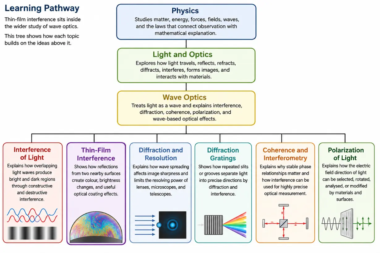
Thin-film interference sits inside the wider study of wave optics. Students first learn that light behaves as a wave, then see how overlapping waves can reinforce or cancel each other. Thin films add an important practical twist: interference can occur when light reflects from two nearby surfaces separated by a very small thickness.
Treats light as a wave and explains interference, diffraction, coherence, polarization, and wave-based optical effects.
This tree chart shows how Thin-Film Interference fits within the Wave Optics cluster, alongside related topics such as interference, diffraction, coherence, and polarization.
This educational tree chart presents the learning pathway for the Wave Optics cluster on Prep4Uni.online. It begins with Physics, narrows to Light and Optics, then to Wave Optics, before branching into six related pages: Interference of Light, Thin-Film Interference, Diffraction and Resolution, Diffraction Gratings, Coherence and Interferometry, and Polarization of Light. The highlighted Thin-Film Interference branch helps students see that colours in soap bubbles, oil films, and optical coatings are part of the wider study of wave behaviour in light.
What Thin-Film Interference REALLY Means
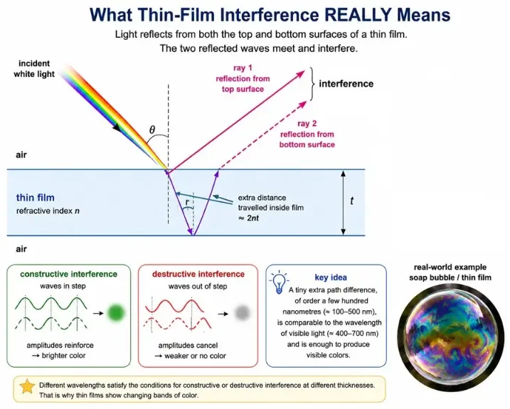
Thin-film interference means that light reflected from a very thin layer does not behave as a single reflected beam. Instead, part of the light reflects from the top surface of the film, while another part enters the film, reflects from the bottom surface, and then emerges back out. These two reflected waves meet and interfere.
If the two reflected waves arrive in step, they reinforce each other and produce a bright reflected colour. If they arrive out of step, they cancel each other partly or completely, reducing that colour in reflection. Since different wavelengths respond differently to the same film thickness, white light can be separated into coloured patterns.
The key idea is that a thin film turns a tiny distance difference into a visible wave effect. The extra distance travelled inside the film may be only a few hundred nanometres, but that is comparable to the wavelength of visible light. This is why a soap bubble can display changing bands of colour even though the film itself is nearly transparent.
This diagram shows that thin-film interference occurs when light reflects from the top and bottom surfaces of a thin film, and the two reflected waves interfere to strengthen or weaken particular colours.
This educational diagram explains what thin-film interference really means. White light falls on a thin transparent film, and two main reflected rays are shown: one from the top surface and one from the bottom surface after travelling through the film. Because the second ray travels an extra distance through the film, the two reflected waves can arrive in step or out of step. When they are in step, constructive interference produces a brighter reflected colour. When they are out of step, destructive interference reduces or removes that colour. The diagram also includes the film thickness, refractive index, and a soap-bubble example to show how a tiny extra path difference can create visible colour patterns.
How Thin-Film Interference Works
Consider a thin transparent film, such as a soap film or an oil layer, surrounded by air. When light reaches the film, several things happen. Some light reflects immediately from the top surface. Some light enters the film, travels through it, reflects from the lower surface, travels back up, and emerges into the air.
The reflected waves then overlap. Their final result depends on two main effects: the extra optical path travelled by the wave that enters the film, and any phase change that occurs during reflection at a boundary.
The optical path inside the film depends on the film thickness t and the refractive index n of the film. For near-normal incidence, the wave that enters the film travels approximately down and back, so its extra distance inside the film is about 2t. Since wavelength is shorter inside a material of refractive index n, the optical path effect is usually written using 2nt.
Reflections from the Two Film Surfaces
A thin film has two important reflecting surfaces. The first is the upper boundary, where light moves from the first medium into the film. The second is the lower boundary, where light inside the film meets the medium beneath it.
These two reflected rays are the main rays used in a basic thin-film interference model. Although more internal reflections can occur, the first two reflected rays are often enough to explain the main bright and dark conditions in introductory physics.
The reflected rays do not necessarily have the same phase. Phase can change when light reflects from a boundary, and this phase change must be considered together with the path difference.
Phase Change on Reflection
A reflected light wave may undergo a phase change depending on the refractive indices of the media. If light reflects from a boundary leading to a medium of higher refractive index, the reflected wave undergoes a phase change of \(\pi\) radians, or half a wavelength.
If light reflects from a boundary leading to a medium of lower refractive index, there is no such half-wavelength phase reversal in the reflected wave.
This rule is central to thin-film interference. It means that the brightness condition is not determined only by the extra path travelled inside the film. The reflection phase changes can reverse the usual expectation of constructive and destructive interference.
Optical Path Difference
The wave reflected from the lower surface of the film travels farther than the wave reflected from the upper surface. For light striking the film nearly normally, this extra optical path difference is approximately:
$$\text{Optical Path Difference} = 2nt$$
Here, n is the refractive index of the thin film, and t is the film thickness. The factor of 2 appears because the light travels down through the film and back up again.
For oblique incidence, the path difference depends on the angle of refraction inside the film. A more general expression involves 2nt cos r, where r is the angle of refraction inside the film. For many introductory examples, near-normal incidence is used to keep the focus on the main concept.
Constructive and Destructive Interference in Reflected Light
The conditions for bright and dark reflected light depend on the number of phase reversals. A common introductory case is a film in air, such as a soap film, where light reflects from air to film at the top surface and from film to air at the bottom surface.
At the top surface, reflection from a higher refractive index gives a phase change of half a wavelength. At the bottom surface, reflection from a lower refractive index gives no such phase change. Therefore, there is one phase reversal between the two reflected rays.
For one phase reversal at near-normal incidence, constructive interference in reflected light occurs when:
$$2nt = \left(m + \frac{1}{2}\right)\lambda$$
Destructive interference in reflected light occurs when:
$$2nt = m\lambda$$
Here, λ is the wavelength of light in air or vacuum, m = 0, 1, 2, 3, … is the order number, n is the refractive index of the film, and t is the film thickness.
Constructive and Destructive Interference in Transmitted Light
Thin-film interference can be observed in reflected light and transmitted light. If a wavelength is strongly reinforced in reflection, it is often reduced in transmission. If a wavelength is cancelled in reflection, it may be transmitted more strongly.
This complementary behaviour is useful in optical coatings. For example, an anti-reflection coating is designed to reduce reflected light at selected wavelengths. The same design helps more light enter the optical instrument or device.
In real films, the situation may be affected by absorption, film thickness variation, multiple reflections, angle of incidence, and the refractive indices of all layers. However, the central idea remains the same: phase relationships determine which wavelengths are strengthened and which are weakened.
Why Thin Films Produce Colours
White light contains many wavelengths. A thin film may reinforce one wavelength while cancelling another. Since different wavelengths correspond to different colours, the reflected light can appear coloured even if the film itself has no strong pigment colour.
Soap bubbles and oil films show changing colours because their thickness is not uniform. Different parts of the film satisfy the interference condition for different wavelengths. As the film drains, stretches, or moves, the colours shift.
Viewing angle also matters. When the angle changes, the effective optical path difference changes. This is why the colours in a bubble or oil film often move and change as the observer or light source moves.
Soap Bubbles and Oil Films
Soap bubbles are one of the most familiar examples of thin-film interference. A soap bubble has a thin layer of water and soap between air on both sides. Light reflected from the outer and inner surfaces of the film interferes, producing colourful bands.
Oil films on water or roads work in a similar way. A very thin layer of oil lies above another medium, and reflected light from the two boundaries interferes. Since the oil thickness varies across the surface, different colours appear in different regions.
These colours are not caused mainly by the oil or soap acting like paint. They are wave colours, produced by selective reinforcement and cancellation of wavelengths.
Anti-Reflection Coatings
Thin-film interference is used deliberately in anti-reflection coatings. These coatings are applied to lenses, camera optics, eyeglasses, solar panels, and sensors to reduce unwanted reflections.
A simple anti-reflection coating can be designed so that light reflected from the top and bottom surfaces of the coating interferes destructively for a selected wavelength. If reflected light is reduced, more light enters the lens or device.
For a quarter-wave coating at near-normal incidence, a common design condition is:
$$t = \frac{\lambda}{4n}$$
Here, t is the coating thickness, λ is the target wavelength in air or vacuum, and n is the refractive index of the coating. This thickness makes the round-trip optical path difference equal to half a wavelength, helping the reflected waves cancel under suitable phase conditions.
Newton’s Rings
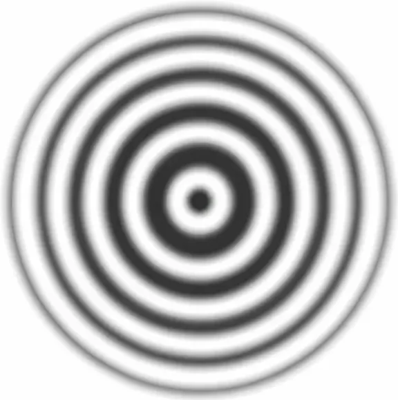
Newton’s rings are circular interference fringes formed when a curved lens rests on a flat glass plate. A very thin air film exists between the curved surface and the flat surface. The thickness of this air film increases gradually outward from the point of contact.
Because the film thickness changes with distance from the centre, different rings satisfy different interference conditions. Under monochromatic light, the pattern appears as alternating bright and dark rings. Under white light, coloured rings may appear near the centre.
Newton’s rings are important because they show how interference can reveal tiny variations in thickness. They also provide a bridge between classroom wave optics and precision optical testing.
Newton’s rings appear as alternating bright and dark circular fringes caused by interference in a thin air film between a curved lens and a flat glass plate.
This simple image shows the characteristic pattern of Newton’s rings: a series of concentric bright and dark circular fringes. The rings are produced when light reflects from the two surfaces of a very thin air film between a curved lens and a flat glass plate. Because the air-film thickness changes gradually from the centre outward, different circular regions satisfy different interference conditions, forming alternating bright and dark rings.
Wedge Films
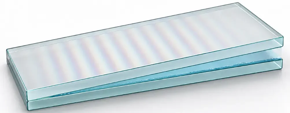
A wedge film is a thin layer whose thickness changes gradually from one end to the other. This can happen when two glass plates touch at one edge and are slightly separated at the other edge.
When monochromatic light reflects from the wedge, the varying thickness produces a series of bright and dark fringes. These fringes are often nearly straight and equally spaced if the wedge angle is small and uniform.
Wedge-film interference can be used to measure very small thicknesses, check surface flatness, and detect slight separations between transparent surfaces.
A wedge film forms when two transparent plates are separated by a very small angle, creating a thin water layer whose changing thickness produces interference fringes.
This artist’s 3D impression shows two transparent glass plates forming a shallow wedge with a thin layer of water between them. Because the water-film thickness gradually changes from one side to the other, reflected light can interfere differently at different positions. The faint iridescent bands visible on the top plate represent interference fringes produced by this changing film thickness. This visual helps students connect wedge films with the broader idea of thin-film interference.
Applications of Thin-Film Interference
Optical Coatings
Optical coatings use controlled thin-film interference to reduce reflection, increase reflection, filter wavelengths, or improve image quality. Camera lenses, microscope objectives, telescope optics, and eyeglasses often use such coatings.
Solar Cells
Solar cells can use anti-reflection coatings to reduce reflected sunlight and allow more light to enter the active semiconductor layers. This improves the amount of light available for conversion into electrical energy.
Colour Effects in Nature
Some natural colours are structural rather than pigment-based. Thin layers in biological structures can produce colours through interference. Examples include certain insect wings, bird feathers, and shells, though many natural colours involve several optical effects working together.
Precision Measurement
Interference fringes can reveal extremely small changes in thickness, flatness, refractive index, or surface shape. Thin-film methods are therefore useful in optical testing, engineering inspection, and scientific measurement.
Decorative and Functional Films
Thin films are used in decorative coatings, security markings, optical filters, display technologies, and protective layers. Their colours and optical properties can be tuned by controlling thickness and material.
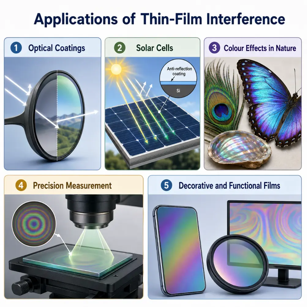
Thin-film interference is used in optical coatings, solar cells, natural structural colours, precision measurement, and decorative or functional films.
This infographic shows major applications of thin-film interference. Optical coatings use controlled interference to reduce or manage reflections in lenses and optical instruments. Solar cells use anti-reflection coatings to allow more sunlight into the active layers. Nature uses thin layers and fine structures to create brilliant structural colours in feathers, wings, and shells. Precision measurement uses interference fringes to reveal very small changes in thickness, flatness, or surface shape. Decorative and functional films use controlled layer thickness to create tuned colours, optical filters, display effects, security markings, and protective surfaces.
Common Misconceptions
Misconception 1: The Colours Come from Pigments in the Film
The colours in soap bubbles and oil films are mainly interference colours, not pigment colours. The film may be nearly transparent, but different wavelengths are reinforced or weakened by interference.
Misconception 2: A Thicker Film Always Produces a Brighter Colour
Brightness depends on whether the reflected waves arrive in step or out of step for a particular wavelength. A greater thickness does not automatically mean a brighter reflection.
Misconception 3: Only Path Difference Matters
Path difference is important, but phase change on reflection is also essential. A half-wavelength phase reversal can change which thicknesses produce bright or dark reflection.
Misconception 4: Thin-Film Interference Happens Only in Soap Bubbles
Soap bubbles are familiar examples, but thin-film interference also occurs in oil films, coatings, air wedges, Newton’s rings, biological structures, optical filters, and engineered nanolayers.
Misconception 5: The Same Condition Applies in Every Film
The interference condition depends on the refractive indices above, inside, and below the film. The number of phase reversals can differ from one situation to another.
Study Tips
When solving thin-film interference problems, first identify the film, its refractive index, and the media above and below it. Then determine whether each reflected ray undergoes a half-wavelength phase change.
Next, decide whether the question is about reflected light or transmitted light. A wavelength that is bright in reflection may be weak in transmission, and a wavelength that is cancelled in reflection may be transmitted strongly.
For introductory problems, many questions assume near-normal incidence. In such cases, the optical path difference is often taken as 2nt. For angled light, the geometry becomes more detailed, and the internal angle of refraction must be considered.
Finally, remember that visible colour depends on wavelength. When white light is used, a thin film may select different colours at different positions because the thickness is not uniform.
Interactive Quick Checks
Quick Check: Thin-Film Interference Basics
Question 1: Why can a transparent soap bubble show bright colours?
A soap bubble has a very thin film. Light reflects from both the outer and inner surfaces of the film. These reflected waves interfere, reinforcing some wavelengths and weakening others. The selected wavelengths appear as colours.
Question 2: What are the two main factors that decide whether the reflected waves reinforce or cancel?
The two main factors are the optical path difference through the film and any phase change that occurs when light reflects from a boundary.
Question 3: For near-normal incidence, why does the optical path difference often contain 2nt?
The ray that enters the film travels down through the film and back up again, giving a physical distance of about 2t. Since the film has refractive index n, the optical path difference is written as 2nt.
Question 4: What happens when light reflects from a boundary leading to a higher refractive index?
The reflected wave undergoes a phase change of \(\pi\) radians, equivalent to half a wavelength.
Question 5: Why must phase change on reflection be considered in thin-film problems?
A phase change can shift a reflected wave by half a cycle. This can change whether a given path difference produces constructive or destructive interference.
Quick Check: Bright and Dark Conditions
Question 1: For one phase reversal, what is the condition for constructive interference in reflected light at near-normal incidence?
For one phase reversal, constructive interference in reflected light occurs when 2nt = (m + 1/2)λ, where m = 0, 1, 2, 3, …
Question 2: For one phase reversal, what is the condition for destructive interference in reflected light at near-normal incidence?
For one phase reversal, destructive interference in reflected light occurs when 2nt = mλ, where m = 0, 1, 2, 3, …
Question 3: A film has n = 1.50 and t = 100 nm. What is 2nt?
2nt = 2 × 1.50 × 100 nm = 300 nm.
Question 4: In a one-phase-reversal case, what minimum non-zero thickness gives bright reflection for wavelength λ?
Use m = 0 in 2nt = (m + 1/2)λ. This gives 2nt = λ/2, so t = λ/(4n).
Question 5: Why can a wavelength that is weak in reflection be strong in transmission?
If reflected waves cancel, less of that wavelength is sent back. Under suitable conditions, more of that wavelength passes through the film instead, so reflection and transmission can behave in a complementary way.
Quick Check: Applications and Interpretation
Question 1: Why do anti-reflection coatings use thin-film interference?
They are designed so that reflected waves from the two surfaces of the coating interfere destructively for selected wavelengths. This reduces unwanted reflection and allows more light to enter the lens or device.
Question 2: What is the common quarter-wave coating thickness condition?
A common quarter-wave condition is t = λ/(4n), where λ is the target wavelength in air or vacuum and n is the refractive index of the coating.
Question 3: Why do soap-bubble colours change as the bubble moves or drains?
The film thickness changes as the bubble drains, stretches, and moves. Since different thicknesses reinforce different wavelengths, the visible colours shift over time.
Question 4: What causes Newton’s rings?
Newton’s rings are produced by interference in the thin air film between a curved lens and a flat glass plate. The film thickness changes gradually outward, producing circular bright and dark fringes.
Question 5: Why are thin-film colours called structural colours rather than pigment colours?
They come from the structure and thickness of the film, which select wavelengths through interference. The colour is not mainly due to chemical pigments absorbing particular wavelengths.
Key Terms
Anti-reflection coating
A thin film layer designed to minimize light reflection through destructive wave phase cancellation.
Constructive reflection condition
$$2nt = \left(m + \frac{1}{2}\right)\lambda$$ The optical path formula that produces a bright reflection maximum in a single-phase-reversal setup.
Destructive reflection condition
$$2nt = m\lambda$$ The path difference equation resulting in light cancellation for a one-phase-reversal boundary arrangement.
Newton’s rings
Concentric circular interference fringes produced by an air film layer caught between flat and curved glass plates.
Optical path difference
$$\text{Optical Path Difference} = 2nt$$ The effective travel distance difference between separate wave reflections at near-normal angles.
Phase change on reflection
A half-wavelength (\(\pi\) radians) wave inversion occurring only when light reflects off a material with a higher refractive index.
Quarter-wave coating thickness
$$t = \frac{\lambda}{4n}$$ The required thin-film baseline parameter optimized for destructive interference arrays.
Thin-film interference
The dynamic wave interaction of light waves reflecting off nearby upper and lower boundary boundaries.
Wedge film
A localized thin material layer featuring a thickness gradient that scales lineally across coordinates.
Review Questions
Question 1
What is thin-film interference?
Answer: Thin-film interference occurs when light waves reflected from the top and bottom surfaces of a thin film overlap and interfere, producing bright or dark reflection for different wavelengths.
Question 2
Why is the film thickness important?
Answer: The thickness determines the extra optical path travelled by the ray reflected from the lower surface. This affects whether the reflected waves arrive in phase or out of phase.
Question 3
What is meant by optical path difference?
Answer: Optical path difference measures the effective path difference after accounting for the refractive index of the material. For near-normal incidence in a thin film, it is often approximately 2nt.
Question 4
When does a reflected wave undergo a half-wavelength phase change?
Answer: A reflected wave undergoes a half-wavelength phase change when it reflects from a boundary leading to a medium of higher refractive index.
Question 5
Why do soap bubbles show changing colours?
Answer: Their film thickness varies across the surface and changes with time. Different thicknesses reinforce or cancel different wavelengths, producing shifting colours.
Question 6
What is the purpose of an anti-reflection coating?
Answer: It reduces unwanted reflection by using thin-film interference so that reflected waves cancel for selected wavelengths.
Question 7
What are Newton’s rings?
Answer: Newton’s rings are circular interference fringes produced by the thin air film between a curved lens and a flat glass plate.
Question 8
Why can thin-film interference be useful for measurement?
Answer: Interference fringes are sensitive to very small changes in thickness, flatness, or surface shape, allowing tiny differences to become visible.
Comprehensive Numerical Problems with Solutions
A soap film features a refractive index of 1.33. Find the minimum non-zero thickness required for constructive reflection of light holding a wavelength of 532 nm, assuming one phase reversal and near-normal incidence.
Solution:
For a single phase reversal, the minimum constructive reflection thickness condition resolves at order \(m = 0\):
Answer: The total optical path length parameters measure exactly 750 nm.
Under a single phase reversal arrangement, an incident wavelength of 500 nm experiences absolute destructive reflection at tracking order m = 2. If the thin film possesses a refractive index of 1.25, find its exact thickness.
Solution:
Apply the one-phase-reversal destructive cancellation rule:
$$2nt = m\lambda$$
Isolate the physical thin-film thickness parameter variable (t):
Answer: The precise material layer thickness is exactly 400 nm.
An optimized industrial anti-reflection coating layer holding a refractive index of 1.38 is optimized for a green light wavelength of 552 nm. Estimate its target quarter-wave thickness metric.
Solution:
Deploy the quarter-wave cancellation thickness formula:
$$t = \frac{\lambda}{4n}$$
Substitute the target wavelength parameters directly:
Answer: The optimized coating thickness checks out at exactly 100 nm.
A protective sheet layer features a refractive index of 1.60 paired with a thickness of 300 nm. For a single phase reversal scenario, calculate the exact wavelength that undergoes complete destructive cancellation at tracking layer index m = 1.
Answer: A wavelength of exactly 960 nm is destructively cancelled (landing in the non-visible near-infrared band).
FAQ
What is thin-film interference in simple terms?
Thin-film interference is the strengthening or weakening of light caused by waves reflecting from the two surfaces of a very thin layer and then overlapping.
Why do soap bubbles show colours?
Soap bubbles show colours because their thin films reinforce some wavelengths of reflected light and cancel others. Different film thicknesses produce different colours.
Why does an oil film on water look colourful?
The oil layer has varying thickness. Light reflected from the top and bottom surfaces of the oil interferes, so different places reflect different colours.
What is the role of refractive index in thin-film interference?
Refractive index affects both the wavelength of light inside the film and the phase change that may occur during reflection. It appears in the optical path difference 2nt.
What is a phase change on reflection?
A phase change on reflection is a shift in the reflected wave. When light reflects from a boundary leading to a higher refractive index, the reflected wave changes phase by half a wavelength.
What is a quarter-wave coating?
A quarter-wave coating has thickness approximately λ/(4n) for a chosen wavelength. It is commonly used to create destructive interference in reflected light and reduce reflection.
Are thin-film colours the same as pigment colours?
No. Pigment colours come from selective absorption by materials. Thin-film colours come mainly from interference caused by film thickness and wave phase.
Why do colours change when the viewing angle changes?
Changing the viewing angle changes the effective optical path difference between the reflected waves. As a result, different wavelengths may be reinforced or cancelled.
What are Newton’s rings used for?
Newton’s rings can be used to study interference, test optical surfaces, measure small thicknesses, and check the curvature or flatness of transparent materials.
Where is thin-film interference used in technology?
It is used in anti-reflection coatings, optical filters, mirrors, solar cells, display coatings, decorative films, precision measurement, and optical testing.
External References
For further reading, the following resources provide useful explanations and additional context on thin-film interference:
Thin-film interference occurs when light reflected from the top and bottom surfaces of a thin transparent layer overlaps. Depending on optical path difference and phase change on reflection, some wavelengths are reinforced while others are weakened.
For near-normal incidence, the optical path difference inside a film is often written as 2nt. The refractive index n, film thickness t, wavelength λ, and reflection phase changes together determine whether reflected light is bright or dark.
In a common one-phase-reversal case, reflected light is bright when 2nt = (m + 1/2)λ and dark when 2nt = mλ. These conditions explain colours in soap bubbles and oil films, as well as the operation of anti-reflection coatings.
Thin-film interference is not just a beautiful effect. It is used in lenses, coatings, solar cells, optical filters, precision testing, and scientific measurement. It shows how wave behaviour at the scale of nanometres can shape what we see at the scale of everyday life.
Reflection Question
When you see colours in a soap bubble or an oil film, are you looking at the material itself, or are you looking at the hidden geometry of light waves interfering across a tiny thickness?