
- Vehicle Dynamics & Tire Mechanics: Formulate longitudinal load transfer, bicycle model lateral yaw response, and non-linear tire traction limits using the Pacejka Magic Formula.
- Electric Powertrain Architecture: Model high-voltage inverter switching, permanent magnet synchronous motor torque-speed envelopes, and electrochemical cell thermal balance.
- Structural Crashworthiness & Safety: Analyze controlled plastic collapse of crumple rails, energy absorption kinematics, and ISO 26262 functional safety architectures.
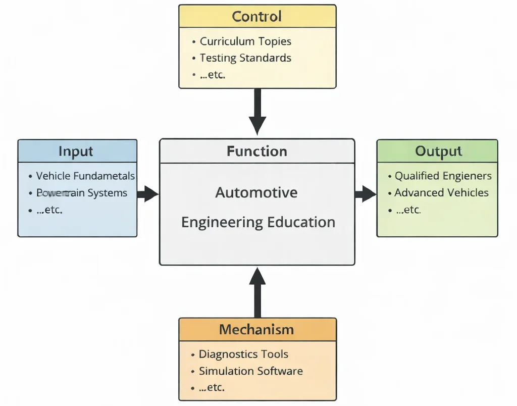
- Inputs (Left): Vehicle architecture requirements, powertrain duty cycles, road adhesion limits (μ), aerodynamic bluff-body drag profiles, and chassis structural constraints.
- Controls (Top): FMVSS/ECE homologation safety mandates, UNECE WP.29 cybersecurity, ISO 26262 ASIL ratings, Euro NCAP crash protocols, and Euro 7 / EPA emissions standards.
- Mechanisms (Bottom): Multi-body dynamics solvers (CarSim, Adams), hardware-in-the-loop (HIL) dynamometers, wind tunnel PIV metrology, battery testing calorimeters, and CAN/CAN-FD bus analyzers.
- Outputs (Right): Validated skateboard chassis platforms, calibrated active stability control maps (ESC/ABS), certified crashworthy passenger safety cells, and high-efficiency electric powertrains.
Mechanical & Automotive Engineering Curriculum Cluster
Navigate the interconnected physical and cyber-physical domains within the Prep4Uni Mechanical Engineering curriculum series:
Mechanical Engineering
The overarching engineering mother discipline governing vehicle kinematics, power units, and machine elements.
Automotive Engineering
Powertrain systems, electric drive integration, chassis suspension dynamics, and crash energy management.
Biomechanical Engineering
Informs crash test dummy biofidelity, occupant deceleration injury thresholds, and ergonomic cabin cockpit architecture.
Control Systems in Mechanical Engineering
Powers anti-lock braking (ABS), electronic stability control (ESC), and active drive-by-wire steering systems.
Fluid Mechanics and Hydraulics
Minimizes aerodynamic drag (Cd), manages underbody downforce, and optimizes brake hydraulic circuits.
Manufacturing and Production Engineering
Drives robotic sheet-metal body stamping, progressive line assembly, and automated laser seam welding.
Mechanical Design and CAD
Parametric Class-A surface modeling, powertrain packaging interference checks, and kinematic suspension routing.
Nanotechnology and Advanced Materials
Integrates carbon-fiber composites, high-strength press-hardened steels, and solid-state battery electrolytes.
Robotics and Automation in Mechanical Engineering
Provides algorithmic foundations for LiDAR trajectory planning, automated guided vehicles, and ADAS actuators.
Solid Mechanics: Stress, Strain & Structural Analysis
Evaluates non-linear plastic buckling in front crash rails, torsional chassis rigidity, and suspension fatigue life.
Thermodynamics and Heat Transfer
Maintains EV traction battery temperature within 20–35°C, cools power inverters, and runs heat-pump HVAC loops.
Vibrations and Acoustics
Suppresses tire road noise, isolates engine/e-motor harmonics, and tunes cabin sound transmission loss.

Deep Technical Foundations: Analytical Vehicle Dynamics & Powertrain Physics
Automotive systems operate at the interface of rigid-body mechanics, non-linear tire viscoelasticity, fluid resistance, and transient electrochemistry. Engineering mastery requires solving the coupled governing equations of longitudinal and lateral motion.
1. Longitudinal Tractive Balance & Aerodynamic Power Demand
A vehicle of total mass m traveling along an incline of gradient angle θ experiences total resistance force Fresist opposing tractive effort Ftract:
$$F_{\text{tract}} - \left( F_{\text{rr}} + F_{\text{aero}} + F_{\text{grade}} \right) = m \cdot a \cdot \gamma_m$$where γm represents the rotational mass factor (γm ≈ 1.05–1.15) accounting for rotating wheel and rotor inertia. Resistance components are expanded as:
$$F_{\text{rr}} = C_{\text{rr}} \cdot m \cdot g \cdot \cos\theta, \quad F_{\text{aero}} = \frac{1}{2} \rho C_d A v^2, \quad F_{\text{grade}} = m \cdot g \cdot \sin\theta$$where Crr is the tire rolling resistance coefficient, ρ is ambient air density, Cd is the aerodynamic drag coefficient, A is frontal projection area, and v is forward velocity. The instantaneous wheel power required to cruise at steady state (a = 0, θ = 0) is cubic with respect to speed:
$$P_{\text{wheel}} = F_{\text{resist}} \cdot v = \left( C_{\text{rr}} m g \right) v + \left( \frac{1}{2} \rho C_d A \right) v^3$$2. Dynamic Longitudinal Load Transfer During Deceleration
During aggressive braking at deceleration rate ax (where deceleration d = |ax|), D'Alembert's inertial force acts at center of gravity (CG) height h, shifting normal ground reactions between the front axle (Wf) and rear axle (Wr) across wheelbase L = a + b:
$$W_f = \frac{m g b}{L} + \frac{m \cdot d \cdot h}{L}, \qquad W_r = \frac{m g a}{L} - \frac{m \cdot d \cdot h}{L}$$where b is the distance from CG to rear axle, and a is distance from CG to front axle. The peak attainable deceleration without wheel lockup on a road surface of peak friction coefficient μ is constrained by tire normal loads:
$$d_{\max} = \mu \cdot g \quad \Longleftrightarrow \quad \text{Braking Distance: } s_{\text{stop}} = \frac{v_0^2}{2 \mu g}$$3. Lateral Handling: Linear Single-Track (Bicycle) Model
For small slip angles (α ≤ 4°), lateral tire cornering force Fy is proportional to tire cornering stiffness Cα: Fyf = Cαf αf and Fyr = Cαr αr. The steering angle δ required to sustain steady-state turning of radius R at forward velocity v is governed by the Understeer Gradient Kus:
$$\delta = \frac{L}{R} + K_{us} \cdot \frac{v^2}{g R}, \qquad K_{us} = \left( \frac{W_f}{C_{\alpha f}} - \frac{W_r}{C_{\alpha r}} \right) \cdot \frac{1}{g}$$When Kus > 0, the vehicle exhibits understeer (inherently directional-stable, requiring increased steering angle as speed rises); when Kus < 0, the vehicle is oversteer (subject to dynamic spin-out above the critical speed vcrit = √(-gL/Kus)).
Contemporary Computational Paradigms in Automotive Engineering
Automotive product development has shifted from costly physical fleet testing to real-time virtual certification, software-defined architectures, and accelerated physics solvers:
PINNs for Thermal Runaway Simulation
Physics-Informed Neural Networks integrate the 3D anisotropic heat diffusion equation with Arrhenius chemical kinetic source terms directly into the training loss. This enables sub-millisecond prediction of pouch-cell thermal runaway and venting gas dynamics during localized physical puncture events.
FNOs for Aerodynamic Body Optimization
Fourier Neural Operators map parametric CAD mesh surface coordinates to external pressure and velocity fields under transient crosswinds. FNOs solve bluff-body wake vortices in fractions of a second, enabling real-time generative shape optimization for minimal drag coefficient.
Digital Twins & Software-in-the-Loop (SIL)
Cloud-coupled digital twins aggregate live CAN-FD telemetry (cell voltage spread, damper velocity, brake disc temperatures). Utilizing Extended Kalman Filtering, the digital twin tracks degradation of battery State of Health (SoH) and brake pad wear across multi-thousand-vehicle commercial fleets.
Systems Engineering Trade-off Matrix
Automotive systems engineering requires balancing vehicle range, crash safety, ride handling, thermal limits, and unit manufacturing costs:
| Chassis / Powertrain Strategy | Primary Engineering Advantage | Bottlenecks & Failure Modes | Mitigation & Control Strategy |
|---|---|---|---|
| Cell-to-Chassis (CTC) Structural Integration | Eliminates modular pack enclosures; increases volumetric energy density by 15–20%; enhances torsional chassis stiffness by over 30%. | Severe serviceability hurdles; cell replacement requires cutting structural floor; localized puncture damages load-bearing vehicle floor. | Incorporate internal corrugated shear webs; use thermally insulating aerogel barriers; design bottom-accessible serviceable module trays. |
| Aggressive Regenerative Deceleration (> 0.3g) | Maximizes kinetic energy recovery; extends urban driving range by up to 25%; significantly reduces friction brake rotor wear. | Rear-wheel braking bias induces yaw instability on low-μ split surfaces; risk of battery overvoltage charging at high State-of-Charge (SoC). | Implement brake blending via Electronic Braking Actuators (EBA); blend with mechanical friction ABS; taper regen power above 90% SoC. |
| Silicon Carbide (SiC) MOSFET Inverters | Enables switching frequencies > 20 kHz; reduces thermal switching losses by 70%; enables compact 800V bus architectures. | Extremely high dV/dt slew rates induce severe electromagnetic interference (EMI) and cause electrical motor bearing fluting. | Incorporate ceramic-insulated motor bearings; install shielded symmetric power cabling; design active gate drivers with optimized slew rates. |
| Steer-by-Wire (SbW) Actuation | Removes physical steering column; eliminates driver injury risk from column intrusion during frontal crash; enables variable gear ratios. | Complete loss of tactile driver road feedback; electrical power loss or CAN bus jamming leads to catastrophic steering failure. | Mandate dual-isolated motor windings, fail-operational dual microcontrollers, redundant battery supplies, and active haptic steering wheel actuators. |
Cross-Sector Industrial Implementations
Passenger Electric Vehicles
Automakers utilize mega-casting (high-pressure aluminum die casting) to replace over 70 stamped steel components with a single rear underbody casting, reducing vehicle mass and production cycle times while meeting Euro NCAP structural integrity ratings.
Motorsport Engineering (Formula 1 / WEC)
Powertrain architectures leverage 120-kW kinetic motor generator units (MGU-K) running alongside 1.6-liter turbocharged ICE units operating at > 50% thermal efficiency, coupled with carbon-carbon multi-disc brake friction systems that reach temperatures over 1000°C.
Heavy Commercial Freight (Class 8)
Long-haul transport integrates dual-stack 300-kW Proton Exchange Membrane (PEM) hydrogen fuel cells paired with 700-bar carbon-fiber wrapped hydrogen tanks, achieving 800-km operational range with refuel times under 15 minutes.
Autonomous Robotaxi Fleets
Sensor suites combine solid-state 1550-nm LiDAR, 4D imaging radar, and high-resolution HDR cameras with onboard liquid-cooled computing platforms drawing 1.5–2.5 kW, executing real-time sensor fusion at 30 frames per second.
Interactive Simulation: Vehicle Dynamics & Braking Performance
Evaluate real-time braking distance, stopping time, peak kinetic energy dissipation, and tire traction limits under variable road adhesion conditions (μ) using our verified zero-crash canvas architecture.
Braking Kinetics & Skid Limit Solver
STATUS: ACTIVE SOLVERFrequently Asked Questions: Automotive Systems & Regulations
1. What distinguishes modern skate-board EV chassis architectures from traditional internal combustion platforms?
2. How does the Pacejka "Magic Formula" model non-linear tire behavior during extreme maneuvers?
3. Why do 800V electric vehicle architectures charge faster and run cooler than legacy 400V systems?
4. What role does ISO 26262 play in automotive functional safety and drive-by-wire systems?
5. How does aerodynamic drag coefficient (Cd) influence EV range compared to rolling resistance?
6. What is the fundamental difference between passive and active suspension architectures?
7. How do crash boxes and longitudinal rails dissipate impact energy during full-frontal Euro NCAP collisions?
8. How do vehicle-to-everything (V2X) communication protocols support Level 4 autonomous driving safety?
Student Practice & Accreditation Assessment Modules
Section 1: Interactive Knowledge Self-Assessment
Q1: Explain why a forward-mounted vehicle center of gravity (CG) inherently produces an understeer response.
Q2: Formulate the physical mechanisms causing brake fade during repeated high-speed stops.
Q3: Why are permanent magnet synchronous motors (PMSMs) preferred over induction motors for passenger EV traction?
Q4: How does a battery thermal management system (BTMS) suppress thermal runaway propagation between neighboring cells?
Q5: Differentiate between Ackerman steering geometry and Parallel steering geometry in low-speed turning maneuvers.
Q6: Why does an Anti-lock Braking System (ABS) target an optimal longitudinal tire slip ratio of 10% to 20%?
Q7: What is the purpose of a torsional damper in a hybrid or dual-clutch transmission clutch assembly?
Q8: How does electronic torque vectoring stabilize a vehicle during high-speed corner entry?
Section 2: Analytical & Scenario-Based Case Studies
Scenario: During high-speed highway testing, a prototype EV struck an abandoned steel towing hitch at 110 km/h. The road debris penetrated the single-skin 3-mm 6061-T6 aluminum battery baseplate, puncturing bottom-mounted prismatic NMC cells and triggering an exothermic thermal runaway within 40 seconds.
Engineering Evaluation:
1. Structural Impact Resistance: The monolithic aluminum skid plate lacked the ballistic shear strength to resist dynamic localized impact forces exceeding 45 kN.
2. Thermal Isolation: The cell module design utilized conductive aluminum inter-cell spacers that conducted 800°C thermal waves to neighboring cells, initiating runaway propagation.
Corrective Engineering Action: Redesign the enclosure underbody into a multi-layer sandwich structure consisting of a 1.2-mm ultra-high-strength steel (UHSS) strike plate, an energy-absorbing expanded aluminum honeycomb crush core, and an interior ballistic aramid blanket. Separate cells with aerogel insulation pads (k ≈ 0.018 W/(m·K)) and add spring-loaded directional pressure relief valves to vent gases downward away from the passenger cabin.
Scenario: A delivery van underwent sudden 180-degree yaw instability (tail spin) when the driver executed moderate braking while cornering on a wet asphalt surface (μ = 0.35) with a lightly loaded cargo bed.
Engineering Evaluation:
Dynamic load transfer during deceleration reduced the rear axle normal force:
$$W_r = \frac{m g a}{L} - \frac{m \cdot d \cdot h}{L}$$
Because the unladen van had a forward CG bias, the mechanical proportioning valve delivered excessive hydraulic pressure to the rear drum brakes. The rear tires locked before the front tires (λr → 100%), dropping rear tire lateral cornering force to zero and inducing uncontrollable oversteer spin-out.
Corrective Engineering Action: Replace the fixed mechanical proportioning valve with four-channel Electronic Brakeforce Distribution (EBD) integrated into the ABS/ESC module. The calibration software monitors front-to-rear wheel speed differential and restricts rear brake line pressure whenever rear wheel slip exceeds front wheel slip by more than 3%.
Scenario: In an IIHS 25% Small Overlap Frontal barrier crash at 64 km/h, the front left longitudinal rail of an SUV buckled globally outward as an elastic column rather than crushing progressively. This allowed the barrier to strike the A-pillar directly, intruding into the driver footwell by 320 mm.
Engineering Evaluation:
The rail cross-section had uniform wall thickness and lacked trigger notches. Under oblique loading (15-degree impact vector), the lateral bending moment exceeded the section's plastic collapse moment before axial plastic fold mechanisms could initiate:
$$P_{\text{crit}} = \frac{\pi^2 E I}{(K L)^2}$$
The rail collapsed in global Euler bending, failing to absorb impact energy through axial deformation.
Corrective Engineering Action: Redesign the front rails with tailored welded blanks (thicker steel near the firewall, thinner near the bumper) and stamp progressive bead triggers along the front 150 mm. Add an ultra-high-strength steel (boron/martensitic steel) shotgun bracket that deflects oblique loads outboard into the door-ring reinforcement structure.
Scenario: Test drivers of a prototype sports coupe reported front-end steering wander and reduced yaw responsiveness at autobahn speeds exceeding 210 km/h.
Engineering Evaluation:
Wind tunnel testing revealed that stagnation pressure behind the radiator grilles was channeling downward under the front axle, generating a positive aerodynamic front lift coefficient:
$$C_{L,f} = +0.18 \quad \Rightarrow \quad F_{\text{lift},f} = \frac{1}{2} \rho C_{L,f} A v^2 \approx 980 \text{ N at } 210 \text{ km/h}$$
This aerodynamic lift unloaded the front tires, reducing front cornering stiffness Cαf and making the understeer gradient Kus unpredictably non-linear.
Corrective Engineering Action: Install an underbody front splitter with integrated venturi strakes and seal the engine bay floorpan with a smooth composite belly pan. Add hood extraction vents to route radiator air upward over the windshield, reducing front lift to CL,f = −0.04 (net downforce) and stabilizing tire grip at speed.
Scenario: An electric vehicle experienced a piercing 1.8-kHz cabin tonal noise during highway cruise at 110 km/h (motor speed ≈ 8800 RPM), registering 48 dBA inside the passenger compartment.
Engineering Evaluation:
Single-speed EV gearboxes operate without the masking background noise of an ICE. Gear tooth mesh frequency (GMF) aligned with the second structural bending mode of the cast-aluminum gearbox housing:
$$\text{GMF} = \frac{N_{\text{motor}}}{60} \cdot Z_{\text{pinion}} = \frac{8800}{60} \cdot 19 = 2786.6 \text{ Hz}$$
Manufacturing micro-geometry variations (profile lead error) produced transmission error (TE) amplitudes exceeding 2.5 μm, exciting the gearbox casing into resonance and transmitting airborne noise into the cabin.
Corrective Engineering Action: Modify gear tooth micro-geometry using tip relief and crowning (lead modification) to reduce dynamic transmission error below 0.6 μm. Stiffen the aluminum gearbox casing with external cross-ribs to shift the structural natural frequency past 3.2 kHz, and wrap the drive unit in acoustic encapsulation blankets.
Scenario: An autonomous test vehicle equipped with steer-by-wire (SbW) experienced limit-cycle steering oscillation during an ISO 3888-2 double lane-change maneuver at 75 km/h.
Engineering Evaluation:
CAN bus communication delay (12 ms) combined with the physical inertia of the steering rack rack-actuator motor produced an overall closed-loop phase lag of 38 ms. At high-frequency steering reversal inputs (1.5 Hz), this phase lag eroded the control loop's phase margin:
$$\Phi_m \lt 15^\circ$$
The road wheels lagged behind the controller's target yaw-rate angle, causing actuator saturation and unstable vehicle oscillation.
Corrective Engineering Action: Upgrade the communication bus from classic CAN (500 kbps) to deterministic CAN-FD / automotive Ethernet (100 Mbps) to lower transport latency below 1 ms. Implement a feedforward lead-lag compensator in the rack motor controller, and incorporate tire self-aligning torque estimation via a disturbance observer to preserve stability.
Scenario: Heavy-duty electric utility trucks towing trailers up an 8% grade experienced multiple traction inverter shutdowns due to DC-link capacitor bank over-temperature errors.
Engineering Evaluation:
Sustained high motor current operation at low vehicle speeds required high modulation index switching. The metallized polypropylene film capacitors handled severe ripple current:
$$I_{\text{ripple,RMS}} \approx I_{\text{phase}} \sqrt{2m \left( \frac{\sqrt{3}}{4\pi} + \cos^2\phi \left( \frac{\sqrt{3}}{\pi} - \frac{9}{16} m \right) \right)}$$
Ripple current heating (P = I2ripple · ESR) overwhelmed the cooling loop, driving internal capacitor core temperatures past their 105°C dielectric rating and accelerating capacitance loss.
Corrective Engineering Action: Replace standard film capacitors with high-temperature polypropylene film units rated for 125°C, re-route the inverter liquid cold-plate to cool the capacitor base directly, and adjust the space vector PWM switching frequency from 12 kHz to 8 kHz during high-torque, low-speed operation to reduce ripple current generation.
Section 3: Step-by-Step Quantitative Worked Examples
Problem Statement: A high-efficiency electric sedan with frontal area A = 2.25 m2 and drag coefficient Cd = 0.23 cruises at a constant velocity v = 120 km/h (33.33 m/s) in ambient air of density ρ = 1.205 kg/m3. The vehicle mass is m = 1850 kg, and the tire rolling resistance coefficient is Crr = 0.009. Assuming level pavement (θ = 0) and gravity g = 9.81 m/s2, calculate:
(a) The aerodynamic drag force (Faero) in Newtons.
(b) The rolling resistance force (Frr) in Newtons.
(c) The total tractive mechanical power (Pwheel) required at the wheels in kilowatts.
Problem Statement: A passenger car of total mass m = 1500 kg has a wheelbase L = 2.70 m. In static equilibrium, the center of gravity (CG) is located a = 1.15 m behind the front axle (meaning distance to rear axle is b = L − a = 1.55 m), and the CG height is h = 0.52 m. The vehicle executes an emergency stop with deceleration d = 8.50 m/s2. Calculate:
(a) The static normal loads on the front axle (Wf,static) and rear axle (Wr,static) in Newtons.
(b) The dynamic normal load transferred from rear to front (ΔW) in Newtons.
(c) The dynamic axle loads during braking (Wf,dyn, Wr,dyn) and the front dynamic load share percentage.
Problem Statement: An electric crossover of mass m = 2100 kg decelerates from an initial highway speed v1 = 100 km/h (27.78 m/s) down to v2 = 30 km/h (8.33 m/s) approaching an off-ramp. During this braking event, 70% of the total retarding force is provided by the electric motor via regenerative braking (the remaining 30% is dissipated as heat by mechanical friction brakes). The driveline mechanical-to-electrical generator conversion efficiency is ηregen = 86%, and battery charging efficiency is ηbatt = 94%. Calculate:
(a) The total kinetic energy change (ΔEkin) of the vehicle in kilojoules.
(b) The mechanical kinetic energy captured by the motor generator in kilojoules.
(c) The net electrical energy delivered into the battery pack in watt-hours (Wh).
Problem Statement: A vehicle with wheelbase L = 2.65 m has total weight W = 16,000 N, with 60% carried on the front axle (Wf = 9600 N) and 40% on the rear axle (Wr = 6400 N). The cornering stiffness of both front tires combined is Cαf = 82,000 N/rad, and the rear tires combined is Cαr = 94,000 N/rad. Acceleration due to gravity is g = 9.81 m/s2. Calculate:
(a) The Understeer Gradient (Kus) in radians per m/s2 and in degrees per g.
(b) The steering angle (δ) required to negotiate a turn of radius R = 120 m at forward speed v = 90 km/h (25 m/s) in degrees.
Problem Statement: An electric vehicle uses a single-speed reduction gearbox of ratio Gr = 9.5:1 with mechanical driveline efficiency ηtrans = 96%. The driven wheels have an effective rolling radius rdyn = 0.33 m. The vehicle must climb an 18% slope (θ = arctan(0.18) ≈ 10.20°, sinθ ≈ 0.1772) at low speed, which requires an axle tractive force Ftract = 5200 N. Calculate:
(a) The total drive torque required at the vehicle wheels (Twheel) in Newton-meters.
(b) The minimum motor shaft torque (Tmotor) required from the electric machine in Newton-meters.
(c) The rotational speed of the motor (Nmotor) in RPM when cruising at vehicle speed v = 110 km/h (30.56 m/s).
Problem Statement: A passenger car of mass m = 1650 kg strikes a rigid barrier in a full-frontal crash test at v0 = 56 km/h (15.56 m/s). The front structure features twin rectangular longitudinal crush rails that absorb kinetic energy through progressive axial plastic folding. The available deformation crush stroke is scrush = 0.55 m, after which the rigid safety cell must experience no further intrusion. Calculate:
(a) The total kinetic energy (Ekin) dissipated during the impact in kilojoules.
(b) The mean total dynamic crush force (F̄crush) required across the crush stroke in kilonewtons.
(c) The mean dynamic axial load capacity required from each individual rail in kilonewtons.
(d) The average deceleration of the passenger compartment in g-units.