
- Continuum Dynamics & Governing Equations: Formulate differential continuity, Navier-Stokes momentum equations, and the extended Bernoulli mechanical energy balance with major and minor friction losses.
- Internal Pipe Networks & Boundary Layers: Evaluate the Colebrook-White implicit friction factor, Moody diagram regimes, boundary layer separation, and transient water hammer pressure wave acoustics.
- Hydraulic Machinery & System Matching: Calculate pump total dynamic head (TDH), specific speed, Net Positive Suction Head (NPSH), cavitation inception margins, and open-channel gravity flows using Manning's formulation.
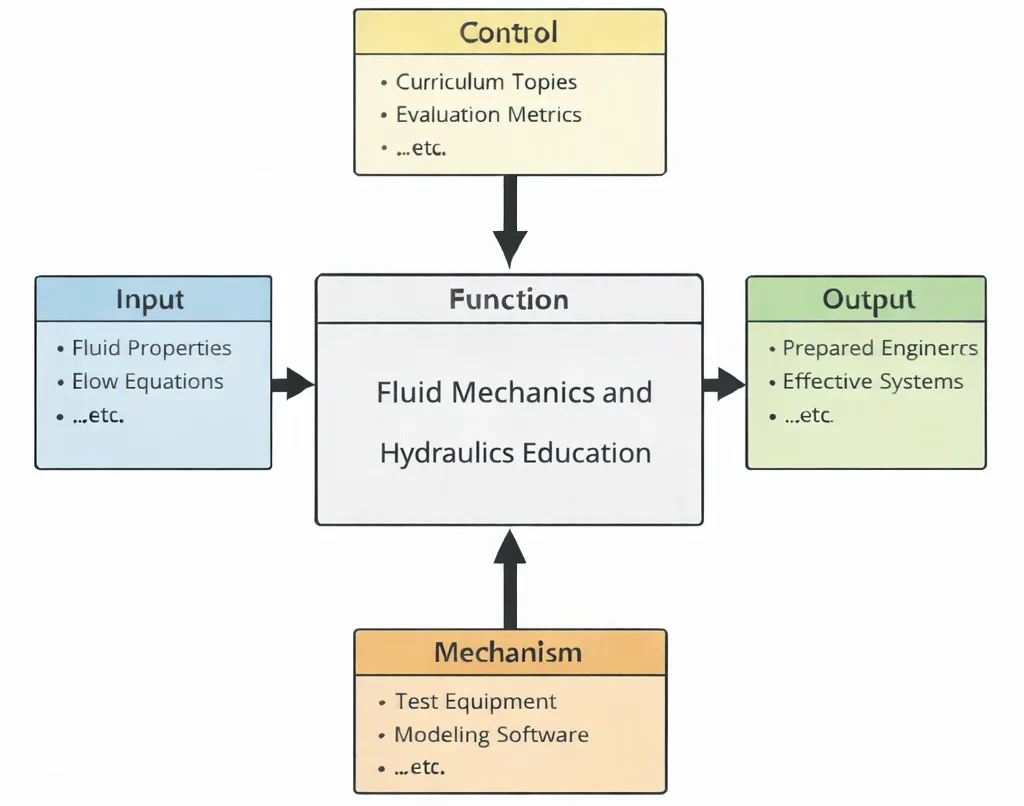
- Inputs (Left): Thermophysical fluid properties (density ρ, dynamic viscosity μ, bulk modulus K), flow boundary conditions, pipeline geometry profiles, reservoir elevations, and fluid power duty cycles.
- Controls (Top): Washington Accord/EUR-ACE engineering criteria, ASME B31.3 piping codes, ISO 4413 hydraulic fluid power standards, ANSI/HI pump test standards, and environmental discharge regulations.
- Mechanisms (Bottom): Particle Image Velocimetry (PIV) flow rigs, high-pressure hydraulic testbenches, industrial pressure transducers, OpenFOAM/ANSYS Fluent CFD solvers, and SCADA-linked flow instrumentation.
- Outputs (Right): Validated piping distribution networks, certified cavitation-free pumping plants, optimized aerodynamic/hydrodynamic profiles, and industry-ready fluid power engineers.
Mechanical & Thermal-Fluid Engineering Curriculum Cluster
Select any foundational pillar below to explore related modules across the PREP4UNI.ONLINE Mechanical Engineering series:
Mechanical Engineering (Hub)
Curricular synthesis, continuum mechanics foundation, cross-disciplinary trade-offs, and simulation testbeds.
Fluid Mechanics & Hydraulics
Navier-Stokes equations, Reynolds transport theorem, boundary layers, pipe friction, and hydraulic turbomachinery.
Thermodynamics & Heat Transfer
First and Second Laws, Rankine/Brayton/Carnot cycles, Fourier conduction, and multi-mode heat exchangers.
Solid Mechanics
Elasticity tensors, Mohr's circle, plane stress/strain, von Mises yield criteria, and beam bending formulations.
Mechanical Design & CAD
Parametric 3D solid modeling, GD&T (ASME Y14.5), fatigue failure theories (Goodman/Soderberg), and DFMA.
Control Systems
Laplace-domain transfer functions, root locus, Bode frequency response, state-space representations, and PID tuning.
Automotive Engineering
EV skateboard chassis, longitudinal/lateral vehicle dynamics, battery pack thermal runaway, and regenerative braking.
Manufacturing & Production
Subtractive machining dynamics, tool-wear equations, metal casting, polymer injection, and Industry 4.0 systems.
Robotics & Automation
Forward/inverse kinematics (Denavit-Hartenberg parameters), Jacobian dynamics, actuator sizing, and PLC architectures.
Biomechanical Engineering
Viscoelastic tissue mechanics, orthopaedic implant design, cardiovascular fluid-structure interaction, and biomaterials.
Vibrations & Acoustics
Lumped-parameter SDOF/MDOF systems, resonance, modal analysis, damping ratios, and acoustic wave equations.
Nanotechnology & Materials
Carbon nanotubes, graphene nanocomposites, grain boundary engineering (Hall-Petch), and surface functionalization.

Deep Technical Foundations: Analytical Formulations in Fluid Mechanics
Unlike rigid-body mechanics, fluids deform continuously under the application of shear stress. Analytical treatment requires formulating balance equations across infinitesimal control volumes, accounting for viscosity, convective acceleration, and frictional energy dissipation.
1. Incompressible Navier-Stokes Equations & Reynolds Transport
For an incompressible Newtonian fluid with constant density ρ and dynamic viscosity μ, the conservation of mass (continuity) and conservation of linear momentum in vector notation are expressed as:
$$\nabla \cdot \mathbf{v} = 0$$ $$\rho \left( \frac{\partial \mathbf{v}}{\partial t} + (\mathbf{v} \cdot \nabla)\mathbf{v} \right) = -\nabla P + \mu \nabla^2 \mathbf{v} + \rho \mathbf{g}$$where v is the velocity vector field, P is static pressure, and g is gravitational body force. The non-linear advective acceleration term (v · ∇)v is responsible for vortex generation, flow separation, and the transition from laminar to turbulent regimes.
2. Extended Energy Equation & Pipe Network Head Loss
Applying the Reynolds Transport Theorem between two cross-sections (1 and 2) of a pipe network yields the extended mechanical energy balance expressed in head units (meters of fluid):
$$\frac{P_1}{\gamma} + \alpha_1 \frac{v_1^2}{2g} + z_1 + h_{\text{pump}} = \frac{P_2}{\gamma} + \alpha_2 \frac{v_2^2}{2g} + z_2 + h_{\text{turbine}} + h_L$$where γ = ρg is specific weight, z is elevation head, and α is the kinetic energy correction factor (α = 2 for fully developed laminar flow; α ≈ 1.05 for turbulent flow). Total head loss hL consists of major frictional losses hf and minor fitting losses hm:
$$h_f = f \left( \frac{L}{D} \right) \frac{v^2}{2g}, \qquad h_m = \sum K_L \frac{v^2}{2g}$$where f is the Darcy-Weisbach friction factor. For laminar flow (Re < 2300), f = 64/Re. For turbulent flow (Re ≥ 4000), f is evaluated implicitly via the Colebrook-White equation or approximated explicitly by the Haaland equation:
$$\frac{1}{\sqrt{f}} \approx -1.8 \log_{10} \left[ \left( \frac{\varepsilon / D}{3.7} \right)^{1.11} + \frac{6.9}{\text{Re}} \right]$$3. Centrifugal Turbomachinery, Affinity Laws & Cavitation Margins
Centrifugal pump performance scales with rotational speed N and impeller diameter D according to the homologous Affinity Laws:
$$\frac{Q_1}{Q_2} = \left(\frac{N_1}{N_2}\right)\left(\frac{D_1}{D_2}\right)^3, \qquad \frac{H_1}{H_2} = \left(\frac{N_1}{N_2}\right)^2\left(\frac{D_1}{D_2}\right)^2, \qquad \frac{P_{w,1}}{P_{w,2}} = \left(\frac{N_1}{N_2}\right)^3\left(\frac{D_1}{D_2}\right)^5$$To prevent destructive bubble collapse (cavitation inception), the Net Positive Suction Head Available (NPSHA) at the pump suction nozzle must exceed the manufacturer's required Net Positive Suction Head (NPSHR) by an engineering safety margin:
$$\text{NPSHA} = \frac{P_{\text{atm}} - P_{\text{vapor}}}{\rho g} + z_{\text{suction}} - h_{L,\text{suction}} \ge \text{NPSHR} + \text{Margin}$$Contemporary Computational Paradigms in Fluid Engineering
Industrial fluid systems development has evolved from purely empirical friction charts to accelerated multi-scale numerical modeling and cyber-physical infrastructure:
PINNs for Turbulent Boundary Layer Modeling
Physics-Informed Neural Networks incorporate the Reynolds-Averaged Navier-Stokes (RANS) momentum equations and Boussinesq turbulent eddy viscosity closures directly into the loss function. This allows rapid reconstruction of near-wall velocity profiles and shear stresses from sparse pressure tap arrays.
Fourier Neural Operators (FNOs) in Aerodynamics
Fourier Neural Operators learn infinite-dimensional continuum mappings from arbitrary 3D surface mesh geometry to external pressure and velocity fields. FNOs resolve full vehicle and turbine wake dynamics up to 1000 times faster than traditional Navier-Stokes mesh solvers.
Digital Twins of Municipal Water Networks
Cloud-coupled hydraulic digital twins solve real-time mass and momentum equations across thousands of pipe nodes using live SCADA flow and pressure telemetry. Utilizing Extended Kalman Filtering, the digital twin detects hidden subsurface main leaks and optimizes pump scheduling to reduce electrical grid demand.
Systems Engineering Trade-off Matrix
Designing fluid systems requires balancing pipe diameter, pump capital expenditure, frictional operating costs, transient pressure ratings, and cavitation limits:
| Hydraulic Design Strategy | Primary Engineering Advantage | Bottlenecks & Failure Modes | Mitigation & Control Strategy |
|---|---|---|---|
| Small Pipe Diameter Selection (D ≪ Dopt) | Substantially reduces upfront piping material, valve procurement costs, structural trenching, and installation footprint. | Flow velocity scales inversely with area (v ∝ 1/D2), driving frictional head loss cubically (hf ∝ 1/D5); escalates pump operating power and risk of erosion. | Perform life-cycle cost optimization balancing capital cost with annualized kilowatt-hour pumping costs over a 20-year service life. |
| High-Speed Centrifugal Pump Selection | Higher operational RPM yields compact casing dimensions, reduced impeller weight, and smaller electric motor frame sizes. | Significantly increases required Net Positive Suction Head (NPSHR ∝ N2); high risk of destructive vapor bubble collapse and impeller pitting. | Install inducer impellers ahead of main suction eye; elevate supply suction reservoir; lower operating fluid temperature to depress vapor pressure. |
| Fast-Closing Quarter-Turn Solenoid Valves | Enables near-instantaneous flow shutoff (< 0.1 s); prevents tank overfills; provides rapid emergency system isolation. | Rapid velocity destruction (Δv) generates severe acoustic pressure surge waves (Water Hammer), rupturing pipe joints and damaging instruments. | Install gas-charged bladder accumulators, surge anticipation relief valves, and program dual-speed slow-closing valve actuators. |
| High-Pressure Hydraulic Power (350+ bar) | Enables high actuator force density (F = P · A), allowing small cylinder diameters and compact, lightweight mobile equipment. | Elevated fluid bulk modulus loss from entrained air; extreme seal leakage; accelerated valve spool erosion and catastrophic pinhole injection hazards. | Specify multi-stage zero-clearance seals, micro-filtered synthetic esters or anti-wear mineral oils, and mandate high-strength seamless steel tubing. |
Cross-Sector Industrial Case Studies
Heavy Mobile Earthmoving Equipment
Excavator hydraulic circuits deploy load-sensing axial piston pumps operating at 380 bar. Proportional closed-center directional valves modulate pilot fluid pressure, coordinating boom lifting and bucket curling while throttling flow to prevent pressure relief valve dumping.
Hydroelectric Pumped-Storage Generation
Francis pump-turbines operating under 450 meters of gross head convert mechanical potential energy into 300 MW of electrical power. Spiral casing geometries and draft tubes are shaped using CFD to maximize recovery of residual kinetic energy while preventing vortex core draft tube surging.
Transcontinental Hydrocarbon Pipelines
Multi-thousand-kilometer crude oil pipelines utilize series-staged multi-stage centrifugal booster pumps. Heavy crude viscosity is conditioned using polymeric drag-reducing agents (DRAs) injected at parts-per-million levels to suppress turbulent core eddies and reduce frictional pressure loss.
Semiconductor Chemical Delivery Systems
High-purity chemical etching tools utilize non-metallic PTFE bellows pumps and electro-pneumatic pinch valves to transport hydrofluoric acid at micro-flow rates under laminar conditions, eliminating metallic contamination and minimizing shear-induced micro-bubble formation.
Interactive Simulation: Venturi Tube Flow Dynamics & Bernoulli Solver
Evaluate real-time flow acceleration, dynamic pressure head conversion, static pressure drop (ΔP), and cavitation susceptibility across a variable-geometry Venturi pipeline constriction using our verified zero-crash canvas architecture.
Venturi Flow Dynamics & Bernoulli Simulator
STATUS: ACTIVE SOLVERFrequently Asked Questions: Fluid Mechanics & Hydraulic Systems
1. What distinguishes fluid mechanics from classical solid mechanics?
2. Why does the Darcy-Weisbach equation supersede the empirical Hazen-Williams formula in modern engineering?
3. What physical conditions trigger cavitation inside hydraulic pumps and control valves?
4. What is the fundamental physical difference between laminar and turbulent flow?
5. How does the hydraulic grade line (HGL) differ from the energy grade line (EGL)?
6. What causes water hammer, and how is the surge pressure wave velocity formulated?
7. Why does Manning's equation apply strictly to open channel gravity flows?
8. How does the Moody diagram classify the completely turbulent (rough pipe) regime?
Student Practice & Accreditation Assessment Modules
Section 1: Interactive Knowledge Self-Assessment
Q1: Formulate the physical significance of the Reynolds number as a ratio of dynamic forces.
Q2: Differentiate between static pressure, dynamic pressure, and stagnation pressure in Bernoulli streamlines.
- Static Pressure (P): The actual thermodynamic fluid pressure exerted on a surface moving parallel to the flow.
- Dynamic Pressure (0.5ρv2): The kinetic energy per unit fluid volume representing pressure rise if fluid velocity were decelerated to zero isentropically.
- Stagnation Pressure (Pstag): The total pressure measured at a zero-velocity stagnation point: $$P_{\text{stag}} = P + \frac{1}{2}\rho v^2$$
Q3: Why must pump operating points be located at the intersection of pump head and system head curves?
Q4: How does boundary layer separation induce aerodynamic form drag and hydraulic head loss?
Q5: Why is Net Positive Suction Head Available (NPSHA) dependent on ambient barometric pressure and fluid temperature?
Q6: What causes hydraulic jump in open channel gravity flows, and what energy transformation occurs?
Q7: Why do positive displacement pumps require pressure relief valves, while centrifugal pumps can be operated against closed valves?
Q8: Formulate how Pascal's Law enables force multiplication in closed hydraulic presses.
Section 2: Analytical & Scenario-Based Case Studies
Scenario: A 400-kW multi-stage centrifugal boiler feedwater pump suffered catastrophic impeller erosion, violent vibration (18 mm/s RMS), and loud crackling noise after boiler operating temperature was raised from 75°C to 95°C.
Engineering Evaluation:
1. Vapor Pressure Surge: Elevating water temperature to 95°C increased saturation vapor pressure from Pvapor(75°C) = 38.6 kPa to Pvapor(95°C) = 84.5 kPa.
2. NPSH Erosion: With atmospheric pressure Patm = 101.3 kPa, suction head margin dropped:
$$\text{NPSHA} = \frac{101.3 - 84.5}{9.81 \cdot 0.962} + 1.2 - 0.9 = 1.78 + 0.3 = 2.08 \text{ m}$$
Because pump required suction head was NPSHR = 3.60 m, the system operated in deep cavitation (NPSHA ≪ NPSHR). Vapor cavities collapsed on the low-pressure blade suction surfaces, eroding 4 mm of chrome-steel alloy.
Corrective Engineering Action: Elevate the deaerator storage tank by 3.5 meters to increase static suction head zs, and install an axial booster inducer upstream of the first-stage impeller eye to lower NPSHR to 1.8 meters.
Scenario: A 600-mm diameter ductile iron cooling water supply main ruptured at an elbow fitting following a sudden 0.25-second emergency trip of an automated butterfly valve, flooding a municipal pumping station.
Engineering Evaluation:
The pipeline carried water at v0 = 3.2 m/s over a length of L = 1200 m. Acoustic wave velocity was a = 1050 m/s. The critical pipeline closure time was:
$$T_{\text{crit}} = \frac{2L}{a} = \frac{2 \cdot 1200}{1050} \approx 2.29 \text{ s}$$
Because valve closure time (tc = 0.25 s) was much less than Tcrit, rapid closure occurred. Applying the Joukowsky equation:
$$\Delta P_{\text{surge}} = \rho \cdot a \cdot \Delta v = 1000 \cdot 1050 \cdot 3.2 = 3.36 \times 10^6 \text{ Pa} = 33.6 \text{ bar}$$
Adding steady operating pressure (6.0 bar), total internal pressure reached 39.6 bar, exceeding the pipeline's 16-bar maximum design rating and shearing fitting bolts.
Corrective Engineering Action: Retrofit the valve actuator with a two-stage hydraulic damper enforcing closure time tc ≥ 8.0 s, and install a 15-m³ nitrogen-charged bladder surge accumulator upstream of the valve.
Scenario: A 200-ton hydraulic forging press exhibited severe low-speed positioning chatter (stick-slip vibration at 3 Hz) and blackened, degraded polyurethane piston seals after 600 hours of continuous cycling.
Engineering Evaluation:
1. Viscosity Degradation: The hydraulic reservoir lacked adequate oil cooling; bulk oil temperature reached 88°C, reducing mineral oil kinematic viscosity from 46 cSt to 8.2 cSt.
2. Boundary Friction: Thin fluid film allowed metal-to-metal boundary contact between the piston head and cylinder wall. The static friction coefficient was substantially higher than kinetic friction (μs ≫ μk), creating non-linear stick-slip hunting during micro-feed motions.
Corrective Engineering Action: Install an air-blast oil-water heat exchanger maintaining bulk oil temperature between 45°C and 55°C, and replace standard polyurethane packings with low-friction bronze-filled PTFE (Teflon) step-seals incorporating elastomeric O-ring energizers.
Scenario: A 75-MW Francis hydro turbine operating at 45% partial load generated deep acoustic pressure pulsations (0.3 times shaft speed) that rattled the powerhouse foundation.
Engineering Evaluation:
Operating at partial load causes water exiting the runner blades to retain substantial residual swirl. In the diverging conical draft tube, this swirling flow encounters an adverse pressure gradient, producing an unstable precessing helical vortex core (the "draft tube rope"). Pressure fluctuations registered amplitudes of ±18% of total head, exciting powerhouse structural resonance.
Corrective Engineering Action: Inject compressed atmospheric air into the center of the draft tube below the runner cone to cushion vortex pulsations, and restrict continuous turbine operation to the high-efficiency operating zone (70–100% load).
Scenario: A 15-kilometer gas transmission pipeline experienced sharp pressure drop and severe acoustic screaming when supplying an industrial combined-cycle power plant during winter peak demand.
Engineering Evaluation:
High volumetric mass flow rates accelerated compressible natural gas velocity to M = 0.45. In long pipelines, Fanno line flow mechanics dictate that wall friction accelerates subsonic compressible flow toward Mach 1:
$$\frac{dM^2}{dx} = \frac{\gamma M^4 \left(1 + \frac{\gamma - 1}{2} M^2\right)}{1 - M^2} \left( \frac{4f}{D} \right) \gt 0$$
As velocity escalated near the downstream discharge header, frictional pressure drop increased exponentially, causing delivery pressure to drop below turbine inlet requirements.
Corrective Engineering Action: Loop the pipeline by installing an identical parallel 400-mm line over the final 8 kilometers, halving gas mass flux and restoring delivery pressure above 45 bar.
Scenario: A commercial building chilled water system suffered multiple pinhole leaks and copper wall thinning along short-radius 90° elbow fittings after three years of operation.
Engineering Evaluation:
To minimize piping material costs, designers selected 50-mm copper headers delivering flow velocities v = 3.8 m/s. Standard ASHRAE codes recommend capping copper water velocities at 1.5–2.0 m/s. The high flow velocity and secondary Dean vortex turbulence at sharp bends stripped the protective copper oxide passivation film, causing continuous erosion-corrosion wear.
Corrective Engineering Action: Upsize distribution headers to 75-mm diameter, lowering velocity to 1.68 m/s, and specify long-radius smooth-sweep elbows (R/D ≥ 1.5).
Scenario: A multi-span highway bridge over a gravel river collapsed when floodwaters undermined the spread footing of its central pier during a 100-year storm event.
Engineering Evaluation:
Bridge piers obstruct open-channel flow, inducing a downward stagnation pressure gradient that drives a high-velocity horseshoe vortex at the pier base. Local bed shear stress exceeded critical sediment movement thresholds:
$$\tau_{\text{bed}} \gg \tau_{\text{crit}}$$
The vortex excavated a 4.5-meter deep scour hole around the central pier footing, eroding bearing gravel and causing structural foundation tilting.
Corrective Engineering Action: Install deep-driven drilled shaft piles extending 12 meters into bedrock, and armor the riverbed surrounding the piers with engineered riprap boulders sized to resist peak flood shear forces.
Section 3: Step-by-Step Quantitative Worked Examples
Problem Statement: A vertical cylindrical storage reservoir with flat base area A = 2.00 m2 is filled with water of density ρ = 1000 kg/m3 to a free-surface height h = 5.00 m. Atmospheric pressure is Patm = 101.325 kPa, and gravitational acceleration is g = 9.81 m/s2. Calculate:
(a) The hydrostatic gauge pressure (Pgage) at the reservoir floor in kPa.
(b) The absolute pressure (Pabs) at the reservoir floor in kPa.
(c) The total downward resultant force (Fbase) exerted by the fluid on the flat floor in kilonewtons.
Problem Statement: Water (ρ = 1000 kg/m3) flows through a horizontal pipeline that constricts from cross-sectional area A1 = 0.080 m2 to A2 = 0.020 m2. Velocity in the upstream pipe is v1 = 2.00 m/s. Calculate:
(a) The total volumetric flow rate (Q) in m3/s and mass flow rate (ṁ) in kg/s.
(b) The flow velocity in the constricted section (v2) in m/s.
(c) The change in kinetic energy velocity head (Δhv) across the transition in meters of water.
Problem Statement: Water at 20°C (ρ = 998.2 kg/m3, dynamic viscosity μ = 1.002 × 10⁻³ Pa·s) flows through a smooth circular pipe of inner diameter D = 0.050 m (50 mm) at a mean velocity v = 1.20 m/s.
(a) Compute the Reynolds number (Re).
(b) Classify the flow regime (laminar, transitional, or turbulent).
(c) Determine the critical velocity (vcrit) below which flow is guaranteed to remain laminar (taking Recrit = 2300).
Because Re ≈ 59,800 is significantly greater than 4000, the flow is fully established Turbulent Flow.
Problem Statement: A hydraulic workshop press utilizes a hand pump piston of radius r1 = 0.020 m (20 mm) connected to an output ram cylinder of radius r2 = 0.100 m (100 mm). The circuit is charged with ISO VG 46 mineral oil. A technician applies an input force F1 = 500 N to the input piston. Calculate:
(a) The internal hydraulic line pressure (Psys) in kPa and bar.
(b) The output lifting force (F2) exerted by the large ram in kilonewtons.
(c) The ideal mechanical force multiplication advantage (MA).
(d) The stroke displacement of the load ram (s2) if the hand pump piston travels s1 = 0.050 m (50 mm).
Problem Statement: A steel pipeline of length L = 100 m and inside diameter D = 0.100 m conveys hydraulic oil of density ρ = 870 kg/m3 at a mean flow velocity v = 3.00 m/s. The Darcy friction factor is f = 0.025. Gravity is g = 9.81 m/s2. Calculate:
(a) The frictional head loss (hf) in meters of fluid.
(b) The frictional pressure drop (ΔPf) along the 100-meter pipe in kPa.
(c) The theoretical pumping power (Ppump) required solely to overcome this line friction in kilowatts.
Problem Statement: A rectangular finished concrete stormwater channel of width b = 2.50 m carries water at uniform normal depth y = 1.00 m. The bed slope is S0 = 0.0010 (0.1% grade), and Manning's roughness coefficient is n = 0.015 s/m1/3. Calculate:
(a) The flow area (A), wetted perimeter (Pw), and hydraulic radius (Rh).
(b) The mean cross-sectional flow velocity (v) in m/s using Manning's equation.
(c) The total volumetric discharge capacity (Q) in m3/s.
(d) The Froude number (Fr) and classify whether the flow is subcritical or supercritical.
Because Fr = 0.455 < 1.0, the flow is established Subcritical Flow (tranquil regime).