
Series and parallel circuits are two basic ways of connecting components in an electrical circuit. In a series circuit, components are connected along one path, so the same current passes through each component. In a parallel circuit, components are connected across separate branches, so current can split and flow through more than one path.
This topic is important because real circuits are rarely made from one resistor alone. Lamps, switches, sensors, appliances, circuit boards, and power systems all depend on how components are connected. A small change in connection pattern can change current, voltage, resistance, brightness, heating, safety, and energy transfer.
Series and parallel circuits also prepare students for more advanced circuit analysis. Once students understand how current and voltage behave in simple networks, they are ready to study Kirchhoff’s laws, RC circuits, AC circuits, impedance, electronics, and power systems.
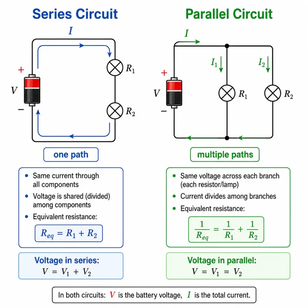
This illustration compares a simple series circuit with a simple parallel circuit. The series circuit shows one path for current, so the same current passes through all components and the battery voltage is shared among them. The parallel circuit shows separate branches, so each branch has the same voltage while the total current divides between the paths. The image also includes equivalent resistance formulas, helping students connect circuit structure with current, voltage, and resistance behaviour.
Electrical Circuits Learning Pathway
This page follows from current, resistance, and Ohm’s law. Once students understand voltage, current, and resistance in a single component, they can study how those ideas behave when components are connected together in series, in parallel, or in mixed networks.
Electricity and Magnetism
Provides the wider physics context for charge, electric fields, voltage, circuits, magnetism, induction, and electromagnetic waves.Electrical Circuits
Introduces how moving charge transfers energy through wires, components, sources, resistors, capacitors, and alternating-current systems.Current, Resistance, and Ohm’s Law
Builds the foundation for circuit thinking by connecting charge flow, voltage, resistance, and energy transfer through Ohm’s law.Series and Parallel Circuits
Explains how current, voltage, and resistance behave when components are connected along one path or across multiple branches.Kirchhoff’s Laws and Circuit Analysis
Extends circuit reasoning to junctions and loops using conservation of charge and conservation of energy.RC Circuits and Time Constants
Connects resistance with capacitance to explain charging, discharging, exponential change, and time delay in circuits.AC Circuits and Impedance
Moves from direct current to alternating current, reactance, impedance, phase difference, and frequency-dependent circuit behaviour.The Core Physical Idea
The core physical idea is that circuit behaviour depends not only on the components used, but also on how they are connected. The same two resistors can behave very differently if they are connected in series instead of parallel.
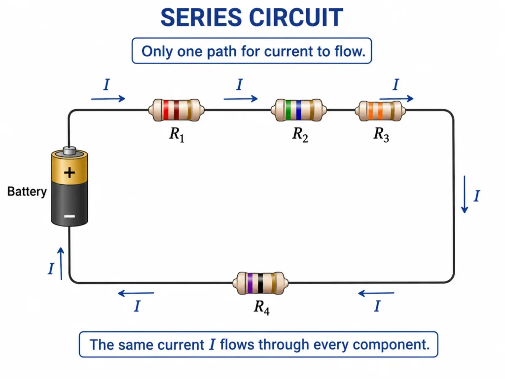
In a series circuit, there is only one path for current. Every charge that passes through one component must also pass through the next component. This means the current is the same through all components in a simple series circuit. However, the voltage supplied by the source is shared among the components.
In a parallel circuit, each branch is connected across the same two points. This means each branch has the same voltage across it. However, the current can split among the branches, and the total current supplied by the source is the sum of the branch currents.
Pictorial Illustration 1: One Path in a Series Circuit
Pictorial Illustration 2: Multiple Paths in a Parallel Circuit
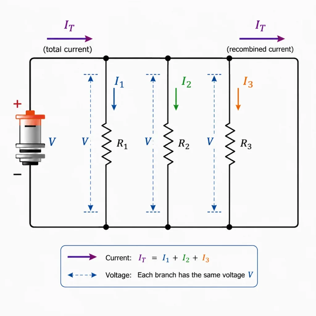
This illustration shows a battery connected to three parallel resistor branches. The total current from the source splits into separate branch currents, passes through the individual branches, and then recombines. The diagram also shows that each branch has the same voltage across it because all branches are connected across the same two points. It helps students see why parallel circuits allow multiple paths for current and why one branch can operate without forcing all current through every component.
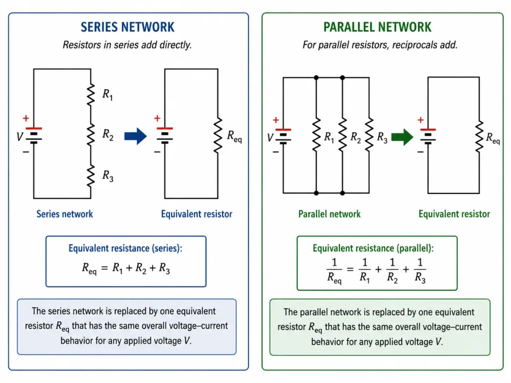
Pictorial Illustration 3: Equivalent Resistance
The One Idea to Remember
Series circuits share current; parallel circuits share voltage.
This sentence is not the whole topic, but it is the best starting memory. In series, there is one current path. In parallel, branches are connected across the same two points, so they share the same potential difference.
How to Visualise the Idea
A useful way to visualise series and parallel circuits is to imagine a route map. A series circuit is like a single narrow road: everyone must pass through the same checkpoints. A parallel circuit is like several roads between the same two places: flow can divide among different routes and recombine later.
Series Means One Route
All charge moving through the circuit follows the same path. This is why the same current passes through each series component.Parallel Means Branches
Charge can split into different branches. The total current is shared among the branches depending on their resistances.Voltage Drops in Series
In a series circuit, the source voltage is divided among the components. The voltage drops add up to the supply voltage.Voltage Is Shared in Parallel
In a parallel circuit, each branch is connected across the same two points, so each branch has the same voltage as the source.Key Equations and What They Mean
For resistors in series, the equivalent resistance is:
\( R_{\text{eq}} = R_1 + R_2 + R_3 + \cdots \)
This means adding more resistors in series increases the total resistance.
For a simple series circuit, the current is the same through all components:
\( I_{\text{total}} = I_1 = I_2 = I_3 = \cdots \)
The voltage drops in a series circuit add to the supply voltage:
\( V_{\text{total}} = V_1 + V_2 + V_3 + \cdots \)
For resistors in parallel, the equivalent resistance is:
\( \frac{1}{R_{\text{eq}}} = \frac{1}{R_1} + \frac{1}{R_2} + \frac{1}{R_3} + \cdots \)
For a simple parallel circuit, the voltage across each branch is the same:
\( V_{\text{total}} = V_1 = V_2 = V_3 = \cdots \)
The total current in a parallel circuit is the sum of the branch currents:
\( I_{\text{total}} = I_1 + I_2 + I_3 + \cdots \)
Series Resistance Adds Directly
Each resistor adds more opposition along the only current path, so the equivalent resistance increases.Parallel Resistance Decreases
Adding a branch gives current another path, so the equivalent resistance becomes smaller than the smallest individual branch resistance.Voltage Splits in Series
The source voltage is shared among series components, with larger resistances usually taking larger voltage drops.Current Splits in Parallel
The total current divides among branches. A lower-resistance branch carries more current than a higher-resistance branch.From Formula to Meaning
The series formula \( R_{\text{eq}} = R_1 + R_2 + R_3 + \cdots \) matches the physical picture of a single path. Every resistor adds more opposition along the same route. This is why adding more resistors in series makes the total resistance larger and reduces current for a fixed supply voltage.
The parallel formula \( \frac{1}{R_{\text{eq}}} = \frac{1}{R_1} + \frac{1}{R_2} + \frac{1}{R_3} + \cdots \) may look less intuitive at first. Physically, however, it says something simple: adding another branch gives current another path. More paths make it easier for charge to flow, so the total resistance decreases.
The current and voltage rules also come from the circuit structure. Series circuits have one route, so current is the same through each component. Parallel circuits connect each branch across the same two nodes, so voltage is the same across each branch.
Worked Example
Problem: Two resistors, \( 4.0 \ \Omega \) and \( 8.0 \ \Omega \), are connected in series to a \( 12 \ \text{V} \) battery. Find the equivalent resistance, the total current, and the voltage across each resistor.
Given: \( R_1 = 4.0 \ \Omega \), \( R_2 = 8.0 \ \Omega \), \( V_{\text{total}} = 12 \ \text{V} \).
Method: Add the series resistances, use Ohm’s law to find total current, then calculate voltage drops.
Solution:
\( R_{\text{eq}} = R_1 + R_2 \)
\( R_{\text{eq}} = 4.0 + 8.0 = 12.0 \ \Omega \)
\( I = \frac{V}{R_{\text{eq}}} \)
\( I = \frac{12}{12.0} = 1.0 \ \text{A} \)
Because the resistors are in series, the same current flows through both.
\( V_1 = IR_1 = (1.0)(4.0) = 4.0 \ \text{V} \)
\( V_2 = IR_2 = (1.0)(8.0) = 8.0 \ \text{V} \)
Interpretation: The total resistance is \( 12.0 \ \Omega \), the current is \( 1.0 \ \text{A} \), and the voltage drops are \( 4.0 \ \text{V} \) and \( 8.0 \ \text{V} \). The voltage drops add to the battery voltage.
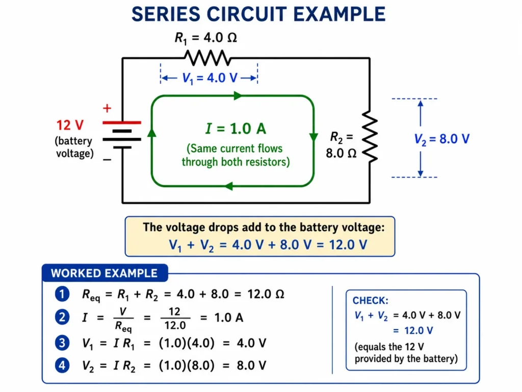
This illustration shows a worked example of a series circuit connected to a 12 V battery. Two resistors, R1 = 4.0 Ω and R2 = 8.0 Ω, are connected along one path, so the same current of 1.0 A flows through both. The diagram shows the voltage drops across the resistors: 4.0 V across R1 and 8.0 V across R2. These voltage drops add to 12.0 V, matching the battery voltage. The picture helps students connect equivalent resistance, Ohm’s law, current, and voltage sharing in a series circuit.
What Students Usually Get Wrong
Students often confuse the rules for series and parallel circuits because they try to memorise formulas without reading the circuit structure. The safest approach is always to identify whether components share the same current path or the same two connection points.
Thinking Current Splits in Series
In a simple series circuit, current does not split because there is only one path.Thinking Voltage Is Always the Same Everywhere
Voltage is the same across parallel branches, but in a series circuit the supply voltage is divided among components.Adding Parallel Resistances Like Series Resistances
Parallel resistances do not add directly. Adding another parallel branch reduces equivalent resistance.Forgetting That Branch Current Depends on Resistance
In parallel circuits, lower-resistance branches carry more current, while higher-resistance branches carry less current.Thinking Components Must Be Side by Side to Be Parallel
Parallel components are defined by shared connection points, not by how the drawing looks on the page.Where This Appears in Real Life
Series and parallel circuits appear in almost every electrical system. They help explain why some devices fail together, why household circuits are usually arranged in parallel, and how engineers control voltage, current, brightness, heating, and safety.
Household Wiring
Many household devices are connected in parallel so that each device receives the same supply voltage and can operate independently.Decorative Lights
Some older light strings used series connections, where one failed bulb could affect the whole string. Modern designs often use more robust combinations.Electronic Circuit Boards
Circuit boards contain networks of series and parallel components that control current, divide voltage, filter signals, and protect components.Battery Packs
Cells may be connected in series to increase voltage or in parallel to increase current capacity and operating time.Sensor Networks
Resistive sensors are often placed in series or parallel arrangements to create measurable voltage changes.Real-World Illustration
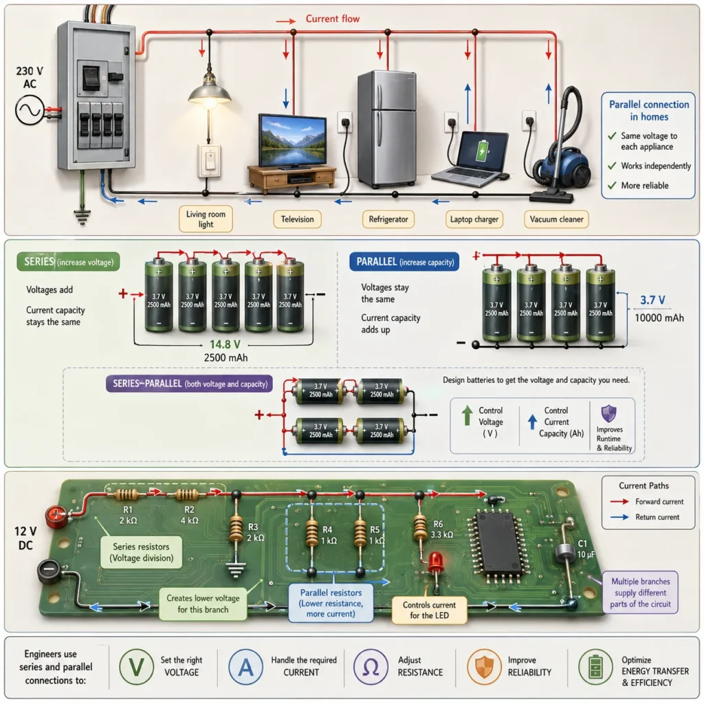
This illustration shows how series and parallel connections appear in practical electrical systems. Household wiring uses parallel branches so that appliances receive the same supply voltage and can operate independently. Battery cells may be connected in series to increase voltage or in parallel to increase current capacity and operating time. Circuit boards use combinations of series and parallel resistor networks to divide voltage, control current, and supply different parts of a system. The picture helps students see that series and parallel circuits are not only classroom diagrams, but useful design patterns in homes, batteries, electronics, and engineering.
Bridge to University Thinking
At school level, series and parallel circuits are usually introduced through simple resistor networks. At university level, the same ideas become part of circuit analysis, network simplification, Kirchhoff’s laws, Thévenin and Norton equivalents, signal processing, power systems, and electronics.
This topic prepares students to reason about complex circuits by reducing them step by step. A complicated circuit may contain many components, but the first question remains simple: which components share the same current, which share the same voltage, and how can the network be simplified without changing its behaviour at the terminals?
Quick Interactive Check
Check Your Understanding of Series and Parallel Circuits
Use these short questions to test whether you are reading circuit structure physically, not just memorising formulas.
In a simple series circuit, what is the same through every component?
Your thinking prompt: Think about whether charge has more than one path.
Suggested answer: The current is the same through every component because there is only one path for charge flow.
In a simple parallel circuit, what is the same across every branch?
Your thinking prompt: Think about branches connected across the same two points.
Suggested answer: The voltage is the same across every branch because each branch is connected across the same two points.
What happens to total resistance when resistors are added in series?
Your thinking prompt: Think about adding more opposition along the only path.
Suggested answer: The total resistance increases because each resistor adds more opposition along the same current path.
What happens to equivalent resistance when another resistor is added in parallel?
Your thinking prompt: Think about giving current another path.
Suggested answer: The equivalent resistance decreases because current has an additional path through the circuit.
Why do lower-resistance branches in a parallel circuit carry more current?
Your thinking prompt: Each branch has the same voltage, so use \( I = \frac{V}{R} \).
Suggested answer: Since each branch has the same voltage, a lower resistance gives a larger current according to \( I = \frac{V}{R} \).
Key takeaway: Series circuits share current, while parallel circuits share voltage.
Review Questions and Answers
- What is a series circuit?Answer: A series circuit is a circuit in which components are connected along one path, so the same current flows through each component.
- What is a parallel circuit?Answer: A parallel circuit is a circuit in which components are connected across multiple branches, giving current more than one path.
- What is the rule for equivalent resistance in series?Answer: For resistors in series, \( R_{\text{eq}} = R_1 + R_2 + R_3 + \cdots \).
- What is the rule for equivalent resistance in parallel?Answer: For resistors in parallel, \( \frac{1}{R_{\text{eq}}} = \frac{1}{R_1} + \frac{1}{R_2} + \frac{1}{R_3} + \cdots \).
- What happens to voltage in a series circuit?Answer: The supply voltage is divided among the series components, and the voltage drops add up to the total voltage.
- What happens to voltage in a parallel circuit?Answer: Each parallel branch has the same voltage across it.
- What happens to current in a series circuit?Answer: The same current flows through every component.
- What happens to current in a parallel circuit?Answer: The total current splits among the branches, and the branch currents add up to the total current.
Thought-Provoking Questions and Answers
- Why are household appliances usually connected in parallel rather than series?Suggested answer: Parallel connections allow each appliance to receive the same supply voltage and operate independently. If one appliance is switched off or fails, the others can still work.
- Why does adding a resistor in series reduce the current from a fixed-voltage source?Suggested answer: Adding resistance along the only path increases the total opposition to current. With the same voltage, a larger resistance gives a smaller current.
- Why does adding a resistor in parallel reduce equivalent resistance?Suggested answer: A new parallel branch gives current an additional path. More available paths make it easier for charge to flow, so the equivalent resistance decreases.
- Why is it dangerous to confuse series and parallel rules?Suggested answer: Using the wrong rule can lead to incorrect current, voltage, resistance, or power calculations. In real systems, this can cause overheating, component damage, or unsafe design.
- Why is circuit structure more important than the visual shape of the drawing?Suggested answer: Components are series or parallel based on how they are connected electrically, not on whether they appear side by side in a diagram. The important issue is whether they share the same current path or the same two nodes.
Numerical Problems and Solutions
- Two resistors, \( 3.0 \ \Omega \) and \( 5.0 \ \Omega \), are connected in series. Find the equivalent resistance.Solution:\( R_{\text{eq}} = R_1 + R_2 \)\( R_{\text{eq}} = 3.0 + 5.0 \)\( R_{\text{eq}} = 8.0 \ \Omega \)Interpretation: Series resistances add directly.
- Two resistors, \( 6.0 \ \Omega \) and \( 3.0 \ \Omega \), are connected in parallel. Find the equivalent resistance.Solution:\( \frac{1}{R_{\text{eq}}} = \frac{1}{6.0} + \frac{1}{3.0} \)\( \frac{1}{R_{\text{eq}}} = \frac{1}{6.0} + \frac{2}{6.0} = \frac{3}{6.0} \)\( R_{\text{eq}} = 2.0 \ \Omega \)Interpretation: The equivalent resistance is smaller than either individual resistor.
- A \( 12 \ \text{V} \) battery is connected to two series resistors of \( 4.0 \ \Omega \) and \( 8.0 \ \Omega \). Find the current.Solution:\( R_{\text{eq}} = 4.0 + 8.0 = 12.0 \ \Omega \)\( I = \frac{V}{R_{\text{eq}}} \)\( I = \frac{12}{12.0} \)\( I = 1.0 \ \text{A} \)Interpretation: The same \( 1.0 \ \text{A} \) flows through both series resistors.
- Two resistors of \( 6.0 \ \Omega \) and \( 12.0 \ \Omega \) are connected in parallel across a \( 12 \ \text{V} \) supply. Find the current in each branch.Solution:Each branch has the same voltage, \( 12 \ \text{V} \).\( I_1 = \frac{V}{R_1} = \frac{12}{6.0} = 2.0 \ \text{A} \)\( I_2 = \frac{V}{R_2} = \frac{12}{12.0} = 1.0 \ \text{A} \)Interpretation: The lower-resistance branch carries the larger current.
- In the previous problem, find the total current supplied by the battery.Solution:\( I_{\text{total}} = I_1 + I_2 \)\( I_{\text{total}} = 2.0 + 1.0 \)\( I_{\text{total}} = 3.0 \ \text{A} \)Interpretation: The source supplies the sum of the branch currents.
Summary
Series and parallel circuits show how circuit structure controls current, voltage, and resistance. In a series circuit, components lie along one path, so the same current flows through each component and the voltage is shared. In a parallel circuit, components lie on separate branches, so each branch has the same voltage and the current divides.
Equivalent resistance helps simplify circuits. Series resistance increases by direct addition, while parallel resistance decreases because current gains additional paths. These ideas are essential for analysing household wiring, electronics, sensors, battery packs, and more complex circuit networks.
Final takeaway: To understand any circuit, first ask how the components are connected: one path means series behaviour; shared nodes and multiple paths mean parallel behaviour.
Glossary
- Series Circuit
- A circuit in which components are connected along one path, so the same current passes through each component.
- Parallel Circuit
- A circuit in which components are connected across multiple branches, giving current more than one path.
- Branch
- A separate path in a circuit through which current can flow.
- Node
- A connection point where circuit elements meet. Parallel branches share the same two nodes.
- Equivalent Resistance
- A single resistance that can replace a resistor network while producing the same overall current-voltage behaviour.
- Voltage Drop
- The potential difference across a component where electrical energy is transferred.
- Total Current
- The current supplied by the source before it splits into branches or after branch currents recombine.
- Branch Current
- The current flowing through one branch of a parallel circuit.
- Load
- A circuit component or device that uses electrical energy, such as a resistor, lamp, heater, or motor.
- Resistor Network
- A group of resistors connected in series, parallel, or a combination of both.
Frequently Asked Questions
What is the main difference between series and parallel circuits?
A series circuit has one current path, while a parallel circuit has multiple current paths. In series, the same current flows through every component. In parallel, the same voltage appears across each branch.
Why is current the same in a series circuit?
Current is the same because there is only one path for charge to follow. Charge that passes through one component must also pass through the next.
Why is voltage the same in a parallel circuit?
Voltage is the same because each branch is connected across the same two points in the circuit.
Why does equivalent resistance increase in series?
Each resistor adds more opposition along the only current path, so the total resistance increases.
Why does equivalent resistance decrease in parallel?
Adding a parallel branch gives current another path. More paths make it easier for charge to flow, reducing the equivalent resistance.
Are household circuits usually series or parallel?
Household circuits are generally arranged in parallel so that devices receive the same supply voltage and can operate independently.
External References
- OpenStax University Physics: Resistors in Series and Parallel — A clear university-level reference for equivalent resistance, current, and voltage rules.
- OpenStax College Physics: Resistors in Series and Parallel — A student-friendly explanation of series and parallel resistor networks.
- Khan Academy: Parallel Resistors — A useful explanation of branches, shared voltage, and current division in parallel circuits.
- The Physics Classroom: Series Circuits — A clear introduction to one-path circuits and series behaviour.
- The Physics Classroom: Parallel Circuits — A helpful guide to multiple-path circuits, voltage sharing, and current division.