
RC circuits combine two important circuit ideas: resistance and capacitance. A resistor controls how quickly charge can move, while a capacitor stores separated charge and energy in an electric field. When they are placed together in a circuit, the result is not an instant change, but a gradual change over time.
This is the central idea of RC circuits: capacitors do not charge or discharge all at once. They respond smoothly. The voltage across a capacitor rises gradually when it charges and falls gradually when it discharges. The speed of this change is controlled by the time constant, written as \( \tau = RC \).
This page helps students understand why RC circuits are so important. They are used in timing, delay circuits, filters, sensors, camera flashes, smoothing circuits, and many electronic systems where a circuit must respond gradually rather than instantly.
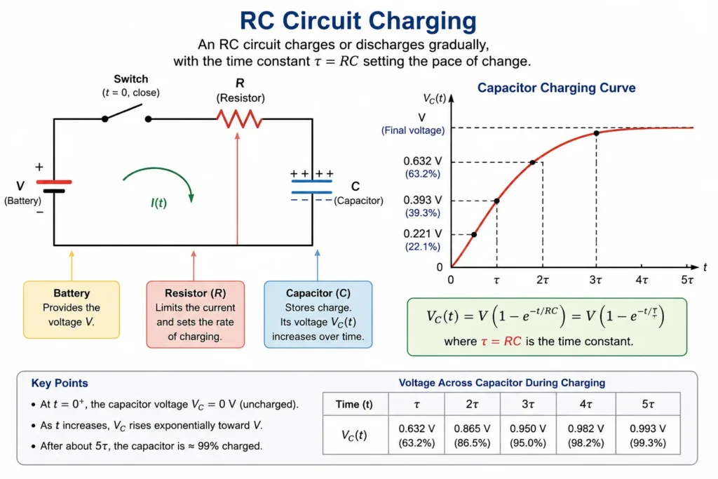
This illustration shows a simple RC charging circuit with a battery, switch, resistor, and capacitor. The resistor limits the current, while the capacitor stores charge and gradually builds up voltage. The charging curve shows that the capacitor voltage does not jump instantly to its final value; instead, it rises smoothly over time. The time constant τ = RC sets the pace of this change, helping students see RC circuits as time-dependent systems.
Electrical Circuits Learning Pathway
This page follows from Ohm’s law, series and parallel circuits, and Kirchhoff’s laws. Once students can analyse current and voltage in steady circuits, RC circuits introduce a new idea: circuit behaviour that changes with time.
Electricity and Magnetism
Provides the wider physics context for charge, electric fields, voltage, circuits, magnetism, induction, and electromagnetic waves.Electrical Circuits
Introduces how moving charge transfers energy through wires, components, sources, resistors, capacitors, and alternating-current systems.Current, Resistance, and Ohm’s Law
Builds the foundation for circuit thinking by connecting charge flow, voltage, resistance, and energy transfer through Ohm’s law.Series and Parallel Circuits
Explains how current, voltage, and resistance behave when components are connected along one path or across multiple branches.Kirchhoff’s Laws and Circuit Analysis
Extends circuit reasoning to junctions and loops using conservation of charge and conservation of energy.RC Circuits and Time Constants
Connects resistance with capacitance to explain charging, discharging, exponential change, and time delay in circuits.AC Circuits and Impedance
Moves from direct current to alternating current, reactance, impedance, phase difference, and frequency-dependent circuit behaviour.The Core Physical Idea
The core physical idea is that a capacitor resists sudden changes in voltage. When a capacitor is uncharged and connected to a battery through a resistor, current initially flows strongly because the capacitor voltage is low. As charge builds up on the capacitor plates, the capacitor voltage rises, the voltage across the resistor falls, and the current gradually decreases.
During discharge, the capacitor begins with stored charge and voltage. When it is connected through a resistor, charge flows out of the capacitor. The capacitor voltage decreases, the current becomes smaller, and the stored energy is gradually transferred to the resistor, usually as heat.
The time constant \( \tau = RC \) tells us how fast this process happens. A larger resistance slows the charge flow. A larger capacitance means more charge must be moved for the voltage to change. Together, \( R \) and \( C \) determine the time scale of the circuit.
Pictorial Illustration 1: Charging an RC Circuit
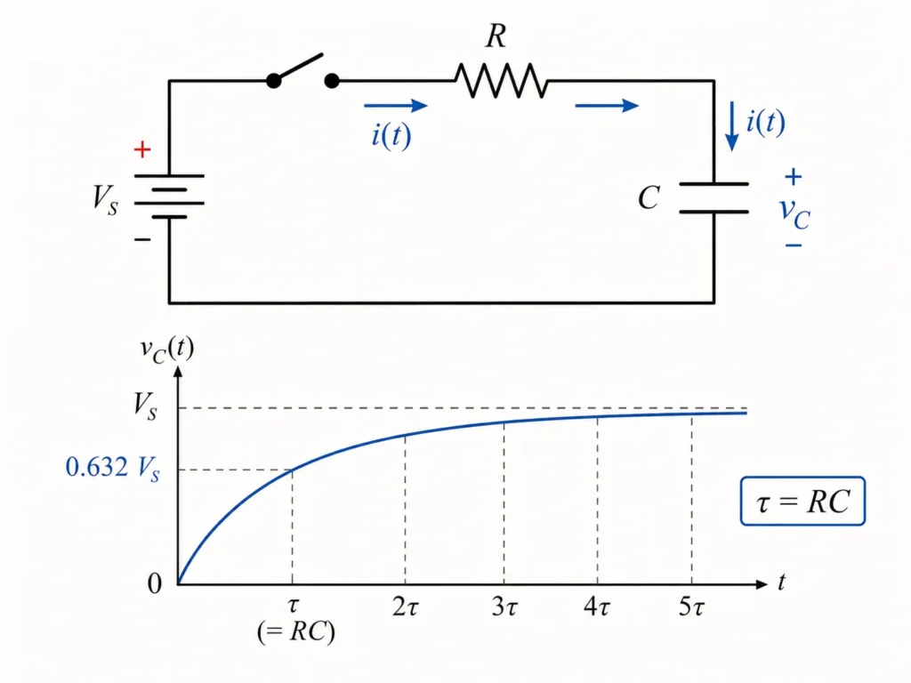
This illustration shows an RC circuit during charging, with a battery, switch, resistor, and capacitor connected in one loop. Current initially flows through the resistor as charge builds up on the capacitor plates. The graph below shows the capacitor voltage rising smoothly toward the supply voltage rather than changing instantly. The time constant τ = RC marks the pace of the charging process, helping students see why the resistor controls how quickly the capacitor charges.
Pictorial Illustration 2: Discharging an RC Circuit
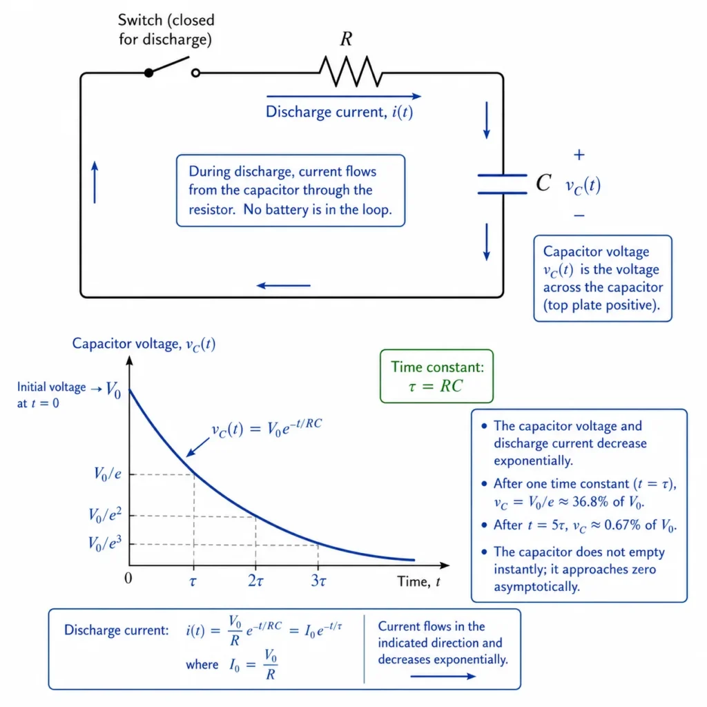
This illustration shows a charged capacitor discharging through a resistor in an RC circuit. As charge leaves the capacitor, current flows through the resistor and gradually becomes smaller. The graph shows the capacitor voltage decreasing exponentially with time, controlled by the time constant τ = RC. The picture helps students understand that a capacitor does not empty instantly; as its voltage falls, the driving current also weakens, so the discharge process slows down.
Pictorial Illustration 3: Meaning of the Time Constant
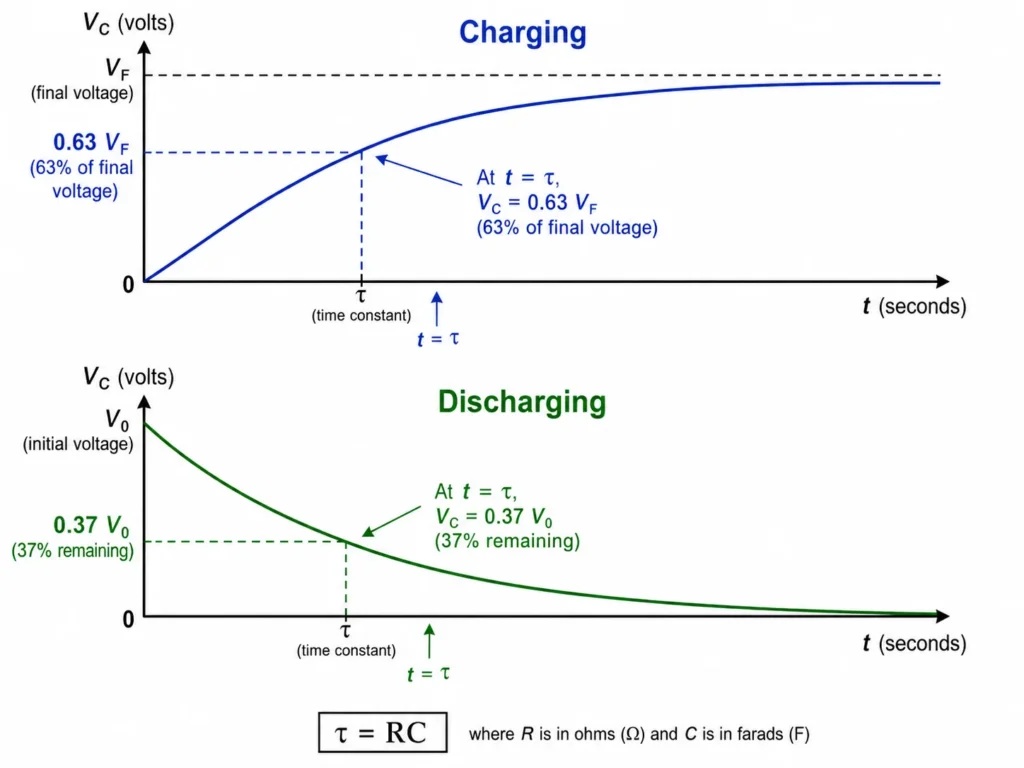
This illustration compares the charging and discharging curves of a capacitor in an RC circuit. The charging curve rises gradually toward its final voltage, reaching about 63% after one time constant. The discharging curve falls gradually from its initial voltage, leaving about 37% after one time constant. The diagram helps students understand that the time constant τ = RC is not the time for complete charging or complete discharging, but a measure of how quickly the capacitor voltage approaches its final state.
The One Idea to Remember
An RC circuit changes gradually because the resistor controls how quickly the capacitor can charge or discharge.
The time constant \( \tau = RC \) is the key quantity. Larger resistance or larger capacitance makes the circuit respond more slowly. Smaller resistance or smaller capacitance makes the circuit respond more quickly.
How to Visualise the Idea
A useful way to visualise an RC circuit is to imagine a water tank filling through a narrow pipe. At first, the difference is large, so filling is fast. As the tank level approaches its final level, filling slows down. The capacitor behaves similarly: it changes quickly at first, then more slowly as it approaches its final voltage.
The Resistor Controls the Rate
A larger resistance makes it harder for charge to move, so the capacitor charges and discharges more slowly.The Capacitor Stores Charge
A larger capacitance stores more charge for each volt, so it takes longer for the voltage to change.The Current Starts Large
At the beginning of charging or discharging, the voltage difference driving current is largest, so current is usually greatest.The Current Fades Away
As the capacitor approaches its final state, the voltage driving current becomes smaller, so current decreases toward zero.Key Equations and What They Mean
The time constant of an RC circuit is:
\( \tau = RC \)
where \( \tau \) is the time constant, \( R \) is resistance, and \( C \) is capacitance.
For a capacitor charging from zero toward a supply voltage \( V_0 \), the capacitor voltage is:
\( V_C(t) = V_0\left(1 – e^{-t/RC}\right) \)
The capacitor charge during charging is:
\( Q(t) = CV_0\left(1 – e^{-t/RC}\right) \)
The charging current is:
\( I(t) = \frac{V_0}{R}e^{-t/RC} \)
For a capacitor discharging from an initial voltage \( V_0 \), the capacitor voltage is:
\( V_C(t) = V_0 e^{-t/RC} \)
The charge during discharge is:
\( Q(t) = Q_0 e^{-t/RC} \)
What \( \tau = RC \) Means
The time constant sets the pace of the circuit response. Larger \( R \) or \( C \) gives a slower response.Why Charging Uses \( 1 – e^{-t/RC} \)
The capacitor voltage starts at zero and approaches its final value gradually.Why Discharging Uses \( e^{-t/RC} \)
The capacitor voltage starts from its initial value and decays gradually toward zero.Why Current Decreases
As the capacitor voltage changes, the voltage across the resistor becomes smaller, so the current decreases.From Formula to Meaning
The equation \( \tau = RC \) explains why both the resistor and capacitor matter. If the resistance is large, charge cannot flow quickly. If the capacitance is large, more charge is needed to produce the same voltage change. Both effects increase the time needed for the circuit to respond.
The charging equation \( V_C(t) = V_0\left(1 – e^{-t/RC}\right) \) says that the capacitor voltage rises quickly at first, then more slowly. It approaches \( V_0 \), but in the ideal mathematical model it never reaches it exactly in a finite time.
The discharging equation \( V_C(t) = V_0 e^{-t/RC} \) says that the capacitor voltage falls quickly at first, then more slowly. After one time constant, the voltage has fallen to about \( 37\% \) of its initial value.
The current equation \( I(t) = \frac{V_0}{R}e^{-t/RC} \) reminds students that current is largest at the beginning of charging and gradually fades toward zero as the capacitor becomes fully charged.
The Thermodynamic Energy Paradox of RC Charging Loops
A fascinating and counterintuitive property of RC charging networks is found when tracking system energy efficiency. When charging an initially uncharged capacitor from zero up to the battery supply potential \(V_0\), the ideal battery delivers a total amount of work defined by the product of its source potential and the accumulated plate charge:
$$ W_{\text{battery}} = Q_{\text{final}} V_0 = (CV_0)V_0 = CV_0^2 $$However, calculating the electrostatic potential energy securely trapped between the capacitor’s conductive plates at full charge reveals a striking discrepancy:
$$ U_{\text{capacitor}} = \frac{1}{2} C V_0^2 $$This means that exactly 50% of the energy supplied by the source is stored in the electric field, while the remaining half (\(\frac{1}{2}CV_0^2\)) is completely lost as thermal dissipation.
Deep Intuition: The Independence of Resistor Sizing
Thermodynamic Boundary Invariants
The real paradox is that this 50% loss factor is completely independent of the value of the resistor (\(R\)).
If you substitute a massive resistor into the loop, the current drops, the charging process slows down, and the energy is dissipated gently over a long period. If you reduce the resistance to nearly zero, the charging process speeds up drastically, and the energy is dissipated in a sudden thermal burst. Even if the wire resistance drops to absolute zero, an electromagnetic field analysis reveals that the remaining energy is still lost to the environment as a pulse of radiated radio waves.
This 50% constraint is a fundamental thermodynamic property of charging a voltage-dependent storage device from a fixed potential source.
Transient Differential Modeling: Deriving the First-Order LTI Expression
At the university level, the exponential expressions used to describe RC circuits are derived analytically by applying Kirchhoff’s Voltage Law (KVL) around the circuit loop at any arbitrary instant in time:
$$ V_0 – v_R(t) – v_C(t) = 0 \Rightarrow V_0 – i(t)R – \frac{q(t)}{C} = 0 $$Because current is defined as the instantaneous rate of charge flow over time (\(i(t) = \frac{dq}{dt}\)), this loop equation forms a first-order linear ordinary differential equation:
$$ R\frac{dq(t)}{dt} + \frac{1}{C}q(t) = V_0 $$To isolate the variables for integration, we rewrite the equation to group the charge terms on one side and the time terms on the other:
$$ \frac{dq}{V_0C – q} = \frac{1}{RC} dt $$Integrating both sides from an initial uncharged state (\(q=0\) at \(t=0\)) yields the natural logarithmic scaling profile that matches classical charging curves:
$$ \int_0^{q(t)} \frac{dq’}{V_0C – q’} = \int_0^t \frac{1}{RC} dt’ \Rightarrow -\ln\left(\frac{V_0C – q(t)}{V_0C}\right) = \frac{t}{RC} $$Exponentiating both sides and substituting the peak charge parameter (\(Q_0 = CV_0\)) yields the classic mathematical definition of charge accumulation over time:
$$ q(t) = Q_0\left(1 – e^{-t/RC}\right) $$This calculus bridge teaches students to view circuits as Linear Time-Invariant (LTI) systems. This foundation is essential for tracking data synchronization speeds inside advanced microprocessor networks, communications equipment, and control systems.
Worked Example
Problem: An RC circuit has \( R = 100 \ \text{k}\Omega \) and \( C = 10 \ \mu\text{F} \). The capacitor is initially uncharged and is connected to a \( 12 \ \text{V} \) supply. Find the time constant and estimate the capacitor voltage after one time constant.
Given: \( R = 100 \ \text{k}\Omega = 1.0 \times 10^5 \ \Omega \), \( C = 10 \ \mu\text{F} = 1.0 \times 10^{-5} \ \text{F} \), \( V_0 = 12 \ \text{V} \).
Method: Use \( \tau = RC \). After one time constant during charging, the capacitor voltage is about \( 63\% \) of the final voltage.
Solution:
\( \tau = RC \)
\( \tau = (1.0 \times 10^5)(1.0 \times 10^{-5}) \)
\( \tau = 1.0 \ \text{s} \)
After one time constant:
\( V_C \approx 0.63V_0 \)
\( V_C \approx 0.63(12) \)
\( V_C \approx 7.6 \ \text{V} \)
Interpretation: The time constant is \( 1.0 \ \text{s} \). After about \( 1.0 \ \text{s} \), the capacitor voltage has risen to about \( 7.6 \ \text{V} \), not yet the full \( 12 \ \text{V} \).
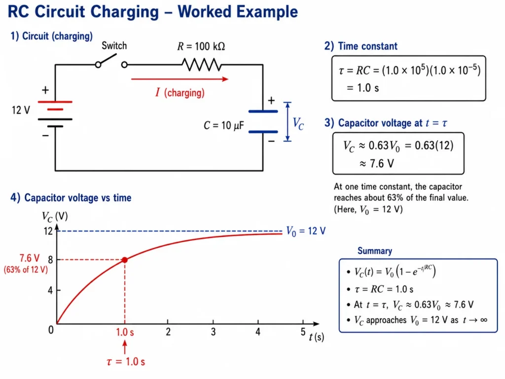
This illustration presents a worked example of an RC charging circuit connected to a 12 V supply. The circuit contains a resistor of 100 kΩ and a capacitor of 10 μF, giving a time constant of τ = RC = 1.0 s. The diagram also shows the charging curve of the capacitor voltage, with the point at one time constant marked clearly. At t = τ, the capacitor voltage has risen to about 63% of its final value, which is approximately 7.6 V. The picture helps students connect the circuit components, the time constant formula, and the meaning of the charging curve in one clear example.
What Students Usually Get Wrong
Many mistakes in RC circuits come from expecting instant changes. Capacitors make circuits time-dependent. Students need to think about initial state, final state, and how quickly the circuit moves between them.
Thinking the Capacitor Charges Instantly
A capacitor does not jump immediately to its final voltage in an RC circuit. The resistor limits the current, so the voltage changes gradually.Thinking One Time Constant Means Fully Charged
After one time constant, a charging capacitor is only about \( 63\% \) of the way to its final voltage.Forgetting That Current Changes with Time
The current is not constant during charging or discharging. It is largest at the start and then decreases.Mixing Up Charging and Discharging Equations
Charging usually uses \( 1 – e^{-t/RC} \), while discharging uses \( e^{-t/RC} \).Ignoring Initial Conditions
The capacitor’s starting voltage matters. A capacitor that is already partly charged behaves differently from one starting at zero volts.Where This Appears in Real Life
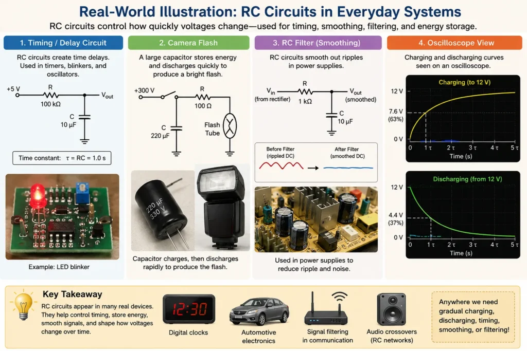
RC circuits appear wherever electrical systems need timing, smoothing, gradual response, signal filtering, or controlled delay. They are simple, but they create behaviour that is essential in electronics.
Timing Circuits
RC circuits can create time delays because the capacitor voltage changes gradually rather than instantly.Camera Flashes
A capacitor can charge slowly and then release stored energy quickly to produce a flash.Power Supply Smoothing
Capacitors help reduce rapid voltage changes, while resistive paths control how quickly charge is added or removed.Signal Filtering
RC circuits can allow some signal frequencies to pass more easily than others, forming simple filters.Touch and Sensor Circuits
Some sensing circuits depend on how capacitance changes and how quickly a voltage rises or falls.Real-World Illustration
Bridge to University Thinking
At school level, RC circuits are often introduced through charging and discharging graphs. At university level, the same ideas become part of differential equations, transient response, filters, signal processing, control systems, instrumentation, electronics, and digital timing circuits.
This topic prepares students for AC circuits and impedance because capacitors respond differently at different frequencies. The time-domain idea of charging and discharging later becomes connected to the frequency-domain idea of capacitive reactance.
Quick Interactive Check
Check Your Understanding of RC Circuits
Use these short questions to test whether you understand RC circuits as time-dependent systems.
What two components form a basic RC circuit?
Your thinking prompt: Look at the name “RC”: what do \( R \) and \( C \) stand for?
Suggested answer: A resistor and a capacitor.
What is the time constant of an RC circuit?
Your thinking prompt: Which product sets the time scale of the circuit response?
Suggested answer: The time constant is \( \tau = RC \).
What happens to the time constant if resistance increases?
Your thinking prompt: Use \( \tau = RC \).
Suggested answer: The time constant increases, so the capacitor charges or discharges more slowly.
During charging, is the current largest at the beginning or near the end?
Your thinking prompt: Think about when the voltage difference driving current is largest.
Suggested answer: The current is largest at the beginning and decreases as the capacitor charges.
After one time constant during charging, is the capacitor fully charged?
Your thinking prompt: Recall the approximate \( 63\% \) rule.
Suggested answer: No. After one time constant, it has reached about \( 63\% \) of its final voltage.
Key takeaway: In an RC circuit, the resistor and capacitor together control how quickly voltage and current change over time.
Review Questions and Answers
- What is an RC circuit?Answer: An RC circuit is a circuit containing a resistor and a capacitor.
- What is the time constant of an RC circuit?Answer: The time constant is \( \tau = RC \).
- What does a larger time constant mean?Answer: A larger time constant means the circuit responds more slowly. The capacitor takes longer to charge or discharge.
- What happens to capacitor voltage during charging?Answer: The capacitor voltage rises gradually toward the supply voltage.
- What happens to capacitor voltage during discharging?Answer: The capacitor voltage falls gradually toward zero.
- What happens to current during charging?Answer: The current starts large and decreases toward zero as the capacitor charges.
- Why does the resistor matter in an RC circuit?Answer: The resistor limits current and controls how quickly charge enters or leaves the capacitor.
- What approximate fraction of final voltage is reached after one time constant during charging?Answer: About \( 63\% \) of the final voltage.
Thought-Provoking Questions and Answers
- Why does a capacitor not charge instantly in an RC circuit?Suggested answer: The resistor limits the current, so charge cannot move onto the capacitor plates instantly. As the capacitor voltage rises, the current decreases, making the process gradual.
- Why is the time constant more useful than asking for the exact time to become fully charged?Suggested answer: In the ideal model, the capacitor approaches its final voltage gradually and never reaches it exactly in a finite time. The time constant gives a practical measure of how fast the process happens.
- Why does current decrease during capacitor charging?Suggested answer: As the capacitor voltage rises, less voltage remains across the resistor. Since current through the resistor depends on that voltage, the current decreases.
- Why are RC circuits useful in timing applications?Suggested answer: The time constant \( RC \) creates a predictable delay. By choosing \( R \) and \( C \), engineers can design circuits that respond over a chosen time scale.
- How does an RC circuit connect steady circuits to AC circuits?Suggested answer: RC circuits show that capacitors respond to changing voltage over time. This prepares students for AC circuits, where voltage and current change continuously.
Numerical Problems and Solutions
- An RC circuit has \( R = 2.0 \ \text{k}\Omega \) and \( C = 500 \ \mu\text{F} \). Find the time constant.Solution:Convert values:\( R = 2.0 \times 10^3 \ \Omega \)\( C = 500 \times 10^{-6} \ \text{F} = 5.0 \times 10^{-4} \ \text{F} \)\( \tau = RC \)\( \tau = (2.0 \times 10^3)(5.0 \times 10^{-4}) \)\( \tau = 1.0 \ \text{s} \)Interpretation: The time constant is \( 1.0 \ \text{s} \).
- A capacitor charges toward \( 10 \ \text{V} \). Estimate its voltage after one time constant.Solution:After one time constant during charging:\( V_C \approx 0.63V_0 \)\( V_C \approx 0.63(10) \)\( V_C \approx 6.3 \ \text{V} \)Interpretation: After one time constant, the capacitor has charged to about \( 6.3 \ \text{V} \).
- A capacitor initially at \( 12 \ \text{V} \) discharges through a resistor. Estimate its voltage after one time constant.Solution:After one time constant during discharge:\( V_C \approx 0.37V_0 \)\( V_C \approx 0.37(12) \)\( V_C \approx 4.4 \ \text{V} \)Interpretation: After one time constant, the capacitor voltage has fallen to about \( 4.4 \ \text{V} \).
- An RC circuit has \( \tau = 0.50 \ \text{s} \) and \( C = 100 \ \mu\text{F} \). Find \( R \).Solution:\( \tau = RC \)\( R = \frac{\tau}{C} \)\( C = 100 \times 10^{-6} \ \text{F} = 1.0 \times 10^{-4} \ \text{F} \)\( R = \frac{0.50}{1.0 \times 10^{-4}} \)\( R = 5.0 \times 10^3 \ \Omega \)Interpretation: The required resistance is \( 5.0 \ \text{k}\Omega \).
- A \( 20 \ \text{V} \) supply charges a capacitor through a \( 4.0 \ \text{k}\Omega \) resistor. Find the initial charging current.Solution:At the instant charging begins, the uncharged capacitor has approximately zero voltage, so the full supply voltage is across the resistor.\( I_0 = \frac{V_0}{R} \)\( I_0 = \frac{20}{4.0 \times 10^3} \)\( I_0 = 5.0 \times 10^{-3} \ \text{A} \)\( I_0 = 5.0 \ \text{mA} \)Interpretation: The initial charging current is \( 5.0 \ \text{mA} \), and it decreases as the capacitor charges.
Summary
RC circuits show how circuits can change with time. A resistor and capacitor together create gradual charging and discharging behaviour, rather than instant voltage changes.
The time constant \( \tau = RC \) sets the pace of the response. A larger resistance or capacitance makes the circuit slower. Charging curves rise toward a final voltage, while discharging curves fall toward zero. Both behaviours are exponential.
Final takeaway: RC circuits are the first major step from steady circuit analysis to time-dependent electrical behaviour.
Glossary
- RC Circuit
- A circuit containing a resistor and a capacitor.
- Time Constant
- The quantity \( \tau = RC \), which sets the time scale for charging or discharging in an RC circuit.
- Charging
- The process in which charge builds up on a capacitor and its voltage rises toward a final value.
- Discharging
- The process in which a capacitor loses stored charge and its voltage falls toward zero.
- Exponential Change
- A type of change where the rate of change depends on the current amount remaining or still needed.
- Initial Current
- The current at the instant charging or discharging begins, often the largest current in the process.
- Final Voltage
- The voltage that the capacitor approaches after a long time in a charging or discharging process.
- Transient Response
- The temporary time-dependent behaviour of a circuit before it settles into its final state.
- Capacitor Voltage
- The potential difference across the capacitor plates.
- RC Filter
- A circuit using a resistor and capacitor to respond differently to different signal frequencies.
Frequently Asked Questions
What is an RC circuit?
An RC circuit is a circuit that contains a resistor and a capacitor. It is important because its voltage and current can change gradually over time.
What does the time constant mean?
The time constant \( \tau = RC \) tells how quickly the circuit responds. A larger time constant means slower charging or discharging.
Is a capacitor fully charged after one time constant?
No. After one time constant, a charging capacitor has reached about \( 63\% \) of its final voltage.
Why does current decrease during charging?
As the capacitor voltage rises, less voltage remains across the resistor, so the current through the resistor decreases.
What happens during capacitor discharge?
The capacitor releases its stored charge through the resistor. Its voltage and current decrease exponentially over time.
Where are RC circuits used?
RC circuits are used in timing circuits, filters, power supply smoothing, sensors, camera flashes, and many electronic systems that need controlled time-dependent behaviour.
External References
- OpenStax University Physics: RC Circuits — A university-level explanation of capacitor charging, discharging, and RC time constants.
- OpenStax College Physics: DC Circuits Containing Resistors and Capacitors — A student-friendly reference on RC circuits and capacitor behaviour.