
Current, resistance, and Ohm’s law form the first gateway into electrical circuits. In electrostatics, students learn that charges can create fields, voltage, and stored energy. In circuits, the focus shifts to what happens when charges are allowed to move through wires, components, and devices.
Electric current describes the rate of charge flow. Voltage provides the energy difference that drives charge through a circuit. Resistance describes how strongly a material or component opposes that flow. Ohm’s law connects these three ideas in one simple relationship: voltage, current, and resistance are not separate facts, but parts of the same circuit behaviour.
This page helps students understand circuits physically before treating them as formula exercises. A resistor is not merely a symbol in a diagram. It is a component where electrical energy is transferred into heat, light, sound, motion, or other useful forms. Ohm’s law gives students their first mathematical language for describing that transfer.
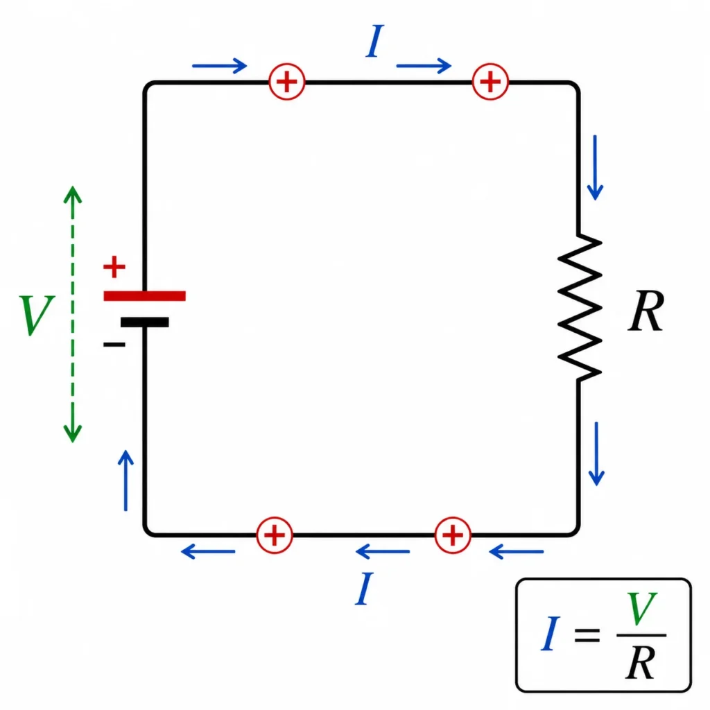
This illustration shows a simple circuit with a battery, resistor, and current arrows. The battery provides voltage, which gives energy per unit charge and drives charge around the circuit. The resistor controls how much current flows for that voltage. The formula I = V/R summarises Ohm’s law, helping students see how increasing voltage increases current, while increasing resistance reduces current.
Electrical Circuits Learning Pathway
This page begins the electrical circuits pathway by focusing on the basic relationship between voltage, current, and resistance. Once students understand this foundation, they are ready to study series and parallel circuits, Kirchhoff’s laws, RC circuits, and alternating-current circuits.
Electricity and Magnetism
Provides the wider physics context for charge, electric fields, voltage, circuits, magnetism, induction, and electromagnetic waves.Electrical Circuits
Introduces how moving charge transfers energy through wires, components, sources, resistors, capacitors, and alternating-current systems.Current, Resistance, and Ohm’s Law
Builds the foundation for circuit thinking by connecting charge flow, voltage, resistance, and energy transfer through Ohm’s law.Series and Parallel Circuits
Shows how current, voltage, and resistance behave when components are connected along one path or across multiple paths.Kirchhoff’s Laws and Circuit Analysis
Extends circuit reasoning to junctions and loops using conservation of charge and conservation of energy.RC Circuits and Time Constants
Connects resistance with capacitance to explain charging, discharging, exponential change, and time delay in circuits.AC Circuits and Impedance
Moves from direct current to alternating current, reactance, impedance, phase difference, and frequency-dependent circuit behaviour.The Core Physical Idea
The core physical idea is that a circuit allows charge to move through a closed conducting path. The current tells us how much charge passes a point each second. The voltage tells us how much energy is available per unit charge. The resistance tells us how strongly the circuit component opposes the current.
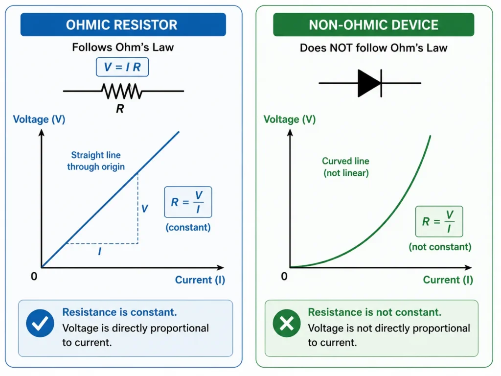
Ohm’s law states that, for many conductors and resistors under suitable conditions, the current through a component is proportional to the voltage across it. If the voltage increases while the resistance remains fixed, the current increases. If the resistance increases while the voltage remains fixed, the current decreases.
This does not mean every device obeys Ohm’s law perfectly. A simple resistor often behaves approximately ohmically, but components such as diodes, filament lamps, and some semiconductor devices may not have a constant resistance under all conditions. For students, Ohm’s law is the first model, not the final description of every electrical device.
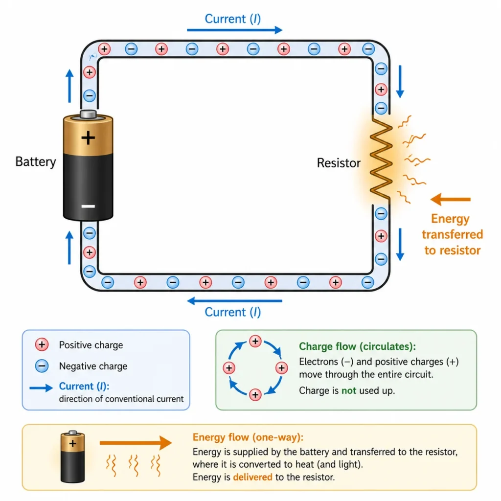
Pictorial Illustration 1: Current as Charge Flow
Pictorial Illustration 2: Voltage, Current, and Resistance
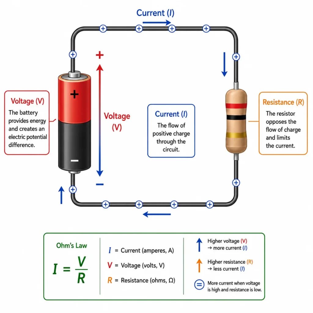
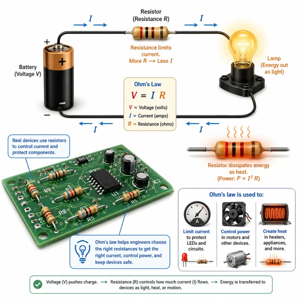
This illustration shows the physical meaning of Ohm’s law in a simple circuit. The battery provides voltage, which represents energy per unit charge and drives charge around the circuit. The moving charges represent electric current, while the resistor opposes the flow and limits how much current can pass for a given voltage. The formula I = V/R links these ideas, helping students see that current increases when voltage increases and decreases when resistance increases.
Pictorial Illustration 3: Ohmic and Non-Ohmic Behaviour
The One Idea to Remember
Ohm’s law says that current depends on both the voltage applied and the resistance in the circuit.
A higher voltage can produce a larger current, but a larger resistance can reduce current. Good circuit thinking therefore requires all three quantities: voltage, current, and resistance.
How to Visualise the Idea
A useful way to visualise a circuit is to imagine charges moving around a closed path. The battery or power supply gives energy to the charges. The charges move through components, where energy is transferred. A resistor controls the rate at which charge flows for a given voltage.
Picture a Closed Path
Current needs a closed conducting path. If the path is broken, charges cannot continue flowing around the circuit.Think of Voltage as Energy per Charge
Voltage tells us how much energy each coulomb of charge can transfer as it moves between two points.Think of Current as Flow Rate
Current tells us how much charge passes a point each second. It is measured in amperes.Think of Resistance as Opposition
Resistance describes how strongly a component resists current. A larger resistance allows less current for the same voltage.Key Equations and What They Mean
Electric current is the rate of flow of charge:
\( I = \frac{\Delta Q}{\Delta t} \)
where \( I \) is current, \( \Delta Q \) is the amount of charge that passes a point, and \( \Delta t \) is the time interval.
Ohm’s law is:
\( V = IR \)
where \( V \) is potential difference, \( I \) is current, and \( R \) is resistance.
The resistance of a uniform wire can be written as:
\( R = \rho \frac{L}{A} \)
where \( \rho \) is resistivity, \( L \) is length, and \( A \) is cross-sectional area.
Electrical power can be written as:
\( P = IV \)
For an ohmic resistor, the power relations can also be written as:
\( P = I^2R \)
\( P = \frac{V^2}{R} \)
What \( I = \frac{\Delta Q}{\Delta t} \) Means
Current is charge flow per unit time. A current of \( 1 \ \text{A} \) means \( 1 \ \text{C} \) of charge passes a point each second.What \( V = IR \) Means
For an ohmic resistor, voltage, current, and resistance are linked. If any two are known, the third can be found.What \( R = \rho \frac{L}{A} \) Means
Longer wires have greater resistance, thicker wires have lower resistance, and different materials resist current differently.What \( P = IV \) Means
Electrical power is the rate at which electrical energy is transferred or converted by a component.From Formula to Meaning
The equation \( I = \frac{\Delta Q}{\Delta t} \) reminds students that current is not the same as charge. Charge is the amount that moves; current is how fast charge moves past a point.
The equation \( V = IR \) shows how the circuit responds to a voltage. If resistance stays the same, doubling the voltage doubles the current. If voltage stays the same, doubling the resistance halves the current.
The equation \( R = \rho \frac{L}{A} \) connects circuit behaviour to material and geometry. A thin, long wire has more resistance than a short, thick wire of the same material. This is why electrical design depends not only on circuit diagrams but also on material choice and physical dimensions.
The equation \( P = IV \) connects circuits to energy. A component with current through it and voltage across it transfers energy. This is why resistors heat up, lamps glow, motors turn, and electronic devices perform useful work.
Worked Example
Problem: A resistor of resistance \( 6.0 \ \Omega \) is connected across a \( 12 \ \text{V} \) battery. Find the current through the resistor and the power transferred by the resistor.
Given: \( R = 6.0 \ \Omega \), \( V = 12 \ \text{V} \).
Method: Use Ohm’s law to find current, then use \( P = IV \) to find power.
Solution:
\( V = IR \)
\( I = \frac{V}{R} \)
\( I = \frac{12}{6.0} \)
\( I = 2.0 \ \text{A} \)
Now calculate the power:
\( P = IV \)
\( P = (2.0)(12) \)
\( P = 24 \ \text{W} \)
Interpretation: The resistor carries a current of \( 2.0 \ \text{A} \) and transfers electrical energy at a rate of \( 24 \ \text{W} \), mainly as thermal energy.
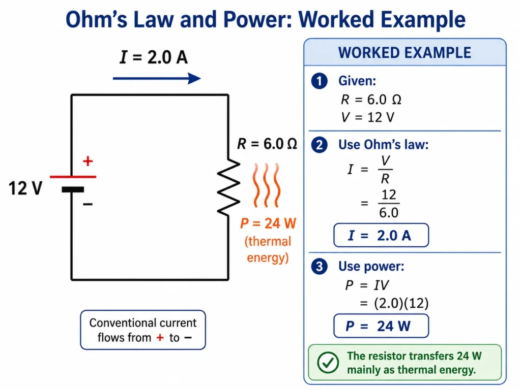
This illustration presents a worked example of a simple electric circuit containing a 12 V battery and a 6.0 Ω resistor. The diagram shows how Ohm’s law is used to calculate the current: I = V/R = 12/6.0 = 2.0 A. It also shows how the power transferred by the resistor is found using P = IV = (2.0)(12) = 24 W. The resistor is shown transferring electrical energy mainly as thermal energy, helping students connect voltage, current, resistance, and power in one clear example.
What Students Usually Get Wrong
Many circuit mistakes come from treating voltage, current, and resistance as separate labels rather than connected ideas. The aim is not only to remember \( V = IR \), but to understand what changes when one quantity changes.
Thinking Current Is Used Up
Current is not consumed by a resistor. Charge flows through the component. Electrical energy is transferred in the component.Confusing Voltage with Current
Voltage is energy per unit charge. Current is charge flow per unit time. A circuit needs both ideas, but they are not the same quantity.Forgetting That Resistance Controls Current
For a fixed voltage, larger resistance produces smaller current. This is one of the central lessons of Ohm’s law.Assuming Every Device Obeys Ohm’s Law
Some components are non-ohmic. Their resistance may change with temperature, voltage, current, or internal structure.Using the Wrong Power Formula Without Context
The formulas \( P = I^2R \) and \( P = \frac{V^2}{R} \) are derived using Ohm’s law, so they apply directly to ohmic resistive behaviour.Where This Appears in Real Life
Current, resistance, and Ohm’s law appear in almost every electrical system. They help explain how batteries power devices, why wires heat up, how resistors protect circuits, and why electrical systems must be designed carefully for safety and efficiency.
Household Devices
Lamps, kettles, chargers, fans, and heaters all involve current flow, voltage supply, resistance, and energy transfer.Electronic Circuits
Resistors are used to control current, divide voltage, protect components, and shape signals in electronic systems.Electrical Safety
Resistance, current, and voltage determine how dangerous an electrical contact may be. Large currents through the body can be harmful.Power Transmission
Electrical energy systems must account for resistance in wires, because resistance can cause energy loss as heat.Sensors and Measurement
Many sensors convert physical changes such as temperature, strain, or light into changes in resistance that circuits can measure.Real-World Illustration
Bridge to University Thinking
At school level, Ohm’s law is often introduced as a simple formula. At university level, the same ideas connect to microscopic charge motion, material resistivity, energy dissipation, circuit models, semiconductor behaviour, signal processing, and electrical engineering design.
This topic prepares students for equivalent resistance, circuit networks, Kirchhoff’s laws, RC circuits, alternating-current circuits, power analysis, electronics, instrumentation, embedded systems, and electrical safety. A strong understanding of voltage, current, and resistance makes later circuit analysis much easier.
Quick Interactive Check
Check Your Understanding of Current, Resistance, and Ohm’s Law
Use these short questions to test whether you are thinking about circuits physically, not just substituting numbers into formulas.
What does electric current measure?
Your thinking prompt: Think about how much charge passes a point each second.
Suggested answer: Electric current measures the rate of charge flow. It tells us how much charge passes a point per unit time.
If the voltage across a fixed resistor is doubled, what happens to the current?
Your thinking prompt: Use \( V = IR \), with \( R \) unchanged.
Suggested answer: The current doubles, because current is proportional to voltage when resistance is constant.
If the resistance is increased while voltage stays the same, what happens to the current?
Your thinking prompt: Rearrange Ohm’s law as \( I = \frac{V}{R} \).
Suggested answer: The current decreases. A larger resistance allows less current for the same voltage.
Is current used up by a resistor?
Your thinking prompt: Think about the difference between charge flow and energy transfer.
Suggested answer: No. Current is not used up. Charge continues through the resistor, while electrical energy is transferred in the resistor.
What does resistance describe?
Your thinking prompt: Ask what limits the current for a given voltage.
Suggested answer: Resistance describes how strongly a component opposes current flow.
Key takeaway: Current is charge flow, voltage is energy per charge, and resistance controls how much current flows for a given voltage.
Advanced Electrokinetics: Microscopic Field Formulation of Ohm’s Law
In introductory electrical modules, Ohm’s Law is universally represented through the macroscopic scalar expression \(V = IR\). While highly effective for analyzing discrete, lumped circuit parameters on a breadboard, this formula fails when applied to non-uniform geometric conductors, continuous plasma matrices, or multi-dimensional electrolytic fields. To analyze these complex environments, university-level physics transforms Ohm’s Law into its local, microscopic vector formulation:
$$ \mathbf{J} = \sigma \mathbf{E} $$Where \(\mathbf{J}\) represents the localized current density vector (the volume of electric charge passing through an infinitesimal cross-sectional area per unit time, measured in \(\text{A/m}^2\)), \(\mathbf{E}\) is the localized electric field vector driving the transport mechanism, and \(\sigma\) is the intrinsic electrical conductivity of the material medium.
Deriving the Macro-Scalar Equation from Field Vectors
Geometric Integration Profiles
To understand how this vector field relationship collapses back into your standard circuit variables, imagine an idealized cylindrical conductor of length \(L\) and uniform cross-sectional area \(A\) subjected to a uniform internal longitudinal electric field. We track the macro-parameters by integrating across the geometry:
1. The total current \(I\) is the flux of the current density vector through the cross-section:
$$ I = \int \mathbf{J} \cdot d\mathbf{A} = J \cdot A \Rightarrow J = \frac{I}{A} $$2. The total potential difference (voltage drop) \(V\) across the boundaries is the line integral of the electric field:
$$ V = -\int_0^L \mathbf{E} \cdot d\mathbf{l} = E \cdot L \Rightarrow E = \frac{V}{L} $$Substituting these two geometric scalar replacements directly back into the microscopic vector statement (\(J = \sigma E\)) yields:
$$ \frac{I}{A} = \sigma \left(\frac{V}{L}\right) \Rightarrow V = I \cdot \left(\frac{L}{\sigma A}\right) $$By introducing material resistivity as the mathematical reciprocal of conductivity (\(\rho = 1/\sigma\)), the term inside the parentheses transforms into the geometric definition of macroscopic resistance (\(R = \rho \frac{L}{A}\)). This step completes the reduction, arriving at \(V = IR\).
Why This Field Model Changes Everything
This vector formulation reveals that the macroscopic version of Ohm’s Law is merely a specialized structural case. In advanced physical systems, if a conductor’s shape changes abruptly, or if an applied external magnetic field introduces asymmetrical forces (such as the Hall Effect), the local electric field vector \(\mathbf{E}\) and the current density vector \(\mathbf{J}\) will rotate away from one another, pointing in completely different directions.
Under these non-linear conditions, conductivity can no longer be evaluated as a simple scalar number; it must be treated as a multidimensional conductivity tensor matrix. This framework allows university researchers to model anisotropy inside advanced crystalline solids, semiconductors, and containment fields inside modern nuclear fusion reactors.
Review Questions and Answers
- What is electric current?Answer: Electric current is the rate at which charge flows past a point. It is given by \( I = \frac{\Delta Q}{\Delta t} \).
- What is the SI unit of current?Answer: The SI unit of current is the ampere, represented by A.
- What does voltage mean in a circuit?Answer: Voltage is electric potential difference. It describes energy transferred per unit charge between two points.
- What is resistance?Answer: Resistance is the opposition a component or material offers to electric current.
- State Ohm’s law.Answer: Ohm’s law states that \( V = IR \), where \( V \) is voltage, \( I \) is current, and \( R \) is resistance.
- What is the SI unit of resistance?Answer: The SI unit of resistance is the ohm, represented by \( \Omega \).
- What does an ohmic resistor mean?Answer: An ohmic resistor has a constant resistance under suitable conditions, so its voltage-current graph is a straight line through the origin.
- What does electrical power represent?Answer: Electrical power is the rate at which electrical energy is transferred or converted by a component.
Thought-Provoking Questions and Answers
- Why is it misleading to say that a resistor “uses up current”?Suggested answer: Current is charge flow, and charge is conserved. A resistor does not consume charge. Instead, electrical energy is transferred in the resistor, often as heat.
- Why is voltage needed for current to flow in a circuit?Suggested answer: Voltage provides an energy difference per unit charge. Without a potential difference, there is no sustained energy transfer to drive charge around the circuit.
- Why can a very small resistance be dangerous in a circuit?Suggested answer: For a fixed voltage, a very small resistance can allow a very large current. This can cause overheating, sparks, component damage, or safety hazards.
- Why are resistors useful in electronics?Suggested answer: Resistors control current, divide voltage, protect sensitive components, shape signals, and help circuits operate within safe limits.
- Why does resistance depend on the material and shape of a wire?Suggested answer: Different materials resist charge motion differently. A longer wire gives charges more material to pass through, while a thicker wire gives more cross-sectional area for charge flow.
Numerical Problems and Solutions
- A current of \( 3.0 \ \text{A} \) flows through a resistor of \( 4.0 \ \Omega \). Find the voltage across the resistor.Solution:\( V = IR \)\( V = (3.0)(4.0) \)\( V = 12 \ \text{V} \)Interpretation: The potential difference across the resistor is \( 12 \ \text{V} \).
- A \( 9.0 \ \text{V} \) battery is connected across a \( 3.0 \ \Omega \) resistor. Find the current.Solution:\( I = \frac{V}{R} \)\( I = \frac{9.0}{3.0} \)\( I = 3.0 \ \text{A} \)Interpretation: The resistor carries a current of \( 3.0 \ \text{A} \).
- A device carries \( 0.50 \ \text{A} \) when connected to \( 12 \ \text{V} \). Find its resistance.Solution:\( R = \frac{V}{I} \)\( R = \frac{12}{0.50} \)\( R = 24 \ \Omega \)Interpretation: The device has a resistance of \( 24 \ \Omega \) under these conditions.
- A charge of \( 20 \ \text{C} \) passes through a wire in \( 5.0 \ \text{s} \). Find the current.Solution:\( I = \frac{\Delta Q}{\Delta t} \)\( I = \frac{20}{5.0} \)\( I = 4.0 \ \text{A} \)Interpretation: Four coulombs of charge pass a point each second.
- A resistor has \( 2.0 \ \text{A} \) of current through it and \( 10 \ \text{V} \) across it. Find the power transferred.Solution:\( P = IV \)\( P = (2.0)(10) \)\( P = 20 \ \text{W} \)Interpretation: The resistor transfers electrical energy at a rate of \( 20 \ \text{J/s} \).
Summary
Current, resistance, and Ohm’s law provide the first working language of circuit physics. Current describes charge flow, voltage describes energy per unit charge, and resistance describes opposition to charge flow.
Ohm’s law connects these ideas through \( V = IR \), helping students predict how circuits respond when voltage or resistance changes. The same ideas also connect to power, energy transfer, electrical safety, circuit design, and real electronic systems.
Final takeaway: A circuit is not just a path for current; it is a system for transferring energy through moving charge, controlled by voltage and resistance.
Glossary
- Electric Current
- The rate of flow of electric charge, measured in amperes.
- Ampere
- The SI unit of electric current. One ampere equals one coulomb per second.
- Voltage
- Electric potential difference between two points, describing energy transferred per unit charge.
- Resistance
- The opposition a material or component offers to electric current.
- Ohm
- The SI unit of resistance, represented by \( \Omega \).
- Ohm’s Law
- The relationship \( V = IR \), connecting voltage, current, and resistance for ohmic components.
- Ohmic Resistor
- A resistor with constant resistance under suitable conditions, producing a straight-line voltage-current graph.
- Non-Ohmic Device
- A device whose voltage-current relationship is not a straight line and whose resistance may change with conditions.
- Resistivity
- A material property that measures how strongly the material resists electric current.
- Electrical Power
- The rate at which electrical energy is transferred or converted by a circuit component.
Frequently Asked Questions
What is the difference between current and voltage?
Current is the rate of charge flow. Voltage is the energy difference per unit charge between two points. Current describes how much charge flows each second, while voltage describes how much energy each unit of charge can transfer.
What does resistance do in a circuit?
Resistance limits current for a given voltage. A larger resistance allows less current to flow, while a smaller resistance allows more current to flow.
Does a resistor use up current?
No. A resistor does not use up current. Charge continues through the resistor, but electrical energy is transferred in the resistor, often as heat.
Does every component obey Ohm’s law?
No. Ohm’s law applies to ohmic components under suitable conditions. Some devices, such as diodes and filament lamps, may have resistance that changes with voltage, current, or temperature.
Why is Ohm’s law important?
Ohm’s law is important because it gives a simple and useful relationship between voltage, current, and resistance. It is one of the first tools students use to analyse circuits.
How is electrical power related to Ohm’s law?
Electrical power is given by \( P = IV \). For ohmic resistors, this can also be written as \( P = I^2R \) or \( P = \frac{V^2}{R} \).
External References
- OpenStax University Physics: Electrical Current — A useful introduction to current, charge flow, and current density.
- OpenStax University Physics: Resistivity and Resistance — A clear explanation of resistance, resistivity, and material effects.
- OpenStax University Physics: Ohm’s Law — A university-level reference for Ohm’s law and voltage-current behaviour.
- The Physics Classroom: Ohm’s Law — A student-friendly explanation of voltage, current, resistance, and circuit calculations.