
Fiber optic sensors use light travelling through an optical fiber to detect changes in the physical world. A fiber that normally carries signals for communication can also become a sensing pathway for strain, temperature, pressure, vibration, bending, rotation, chemical change, liquid level, acoustic waves, and many other quantities.
The basic idea is simple but powerful. When the surrounding environment changes, it may slightly alter the light inside the fiber. The change may appear as a variation in intensity, phase, wavelength, polarization, travel time, or backscattered light. By measuring that optical change carefully, engineers can infer what happened outside the fiber.
This page belongs to the wider Fiber Optics cluster in Light and Optics. Earlier pages explain how fibers guide light by total internal reflection and how fiber modes and dispersion affect pulse behaviour. Fiber optic sensors build on these ideas and apply them to measurement, monitoring, safety, medicine, engineering, and research.
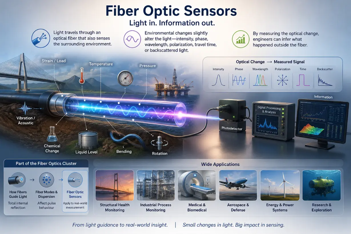
This illustration shows how an optical fiber can act as both a light-guiding path and a sensing device. Environmental changes such as strain, temperature, pressure, bending, vibration, rotation, liquid level, acoustic signals, and chemical change slightly alter the light travelling inside or near the fiber. These changes may appear as variations in intensity, phase, wavelength, polarization, travel time, or backscattered light. By analysing the changed optical signal, engineers can infer what is happening outside the fiber and apply the information in structural monitoring, industrial systems, medicine, aerospace, energy, and research.
Learning Pathway Within the Fiber Optics Module
Fiber optic sensors are easier to understand when they are placed in the correct learning sequence. A student should first understand how light is trapped inside a fiber, then how signals change as they travel, and finally how those changes can be deliberately measured as sensing information. Use the roadmap below to navigate across the cluster levels:
Total Internal Reflection and Optical Fibers
Learn how light remains guided inside a fiber core when it meets the core-cladding boundary under the correct conditions.
Fiber Modes and Dispersion
Study how different guided modes, wavelengths, and propagation effects influence pulse spreading, bandwidth, and signal clarity.
Optical Fiber Communication
This page shows how optical fibers transmit information using light pulses, modulation, receivers, repeaters, and network systems.
Optical Amplifiers and Signal Loss
This page examines attenuation, scattering, absorption, splices, connectors, optical amplifiers, and signal recovery in fiber systems.
Fiber Optic Sensors
Current module. This page explains how optical fibers can act as sensitive measuring devices for strain, temperature, pressure, chemical change, and structural monitoring.
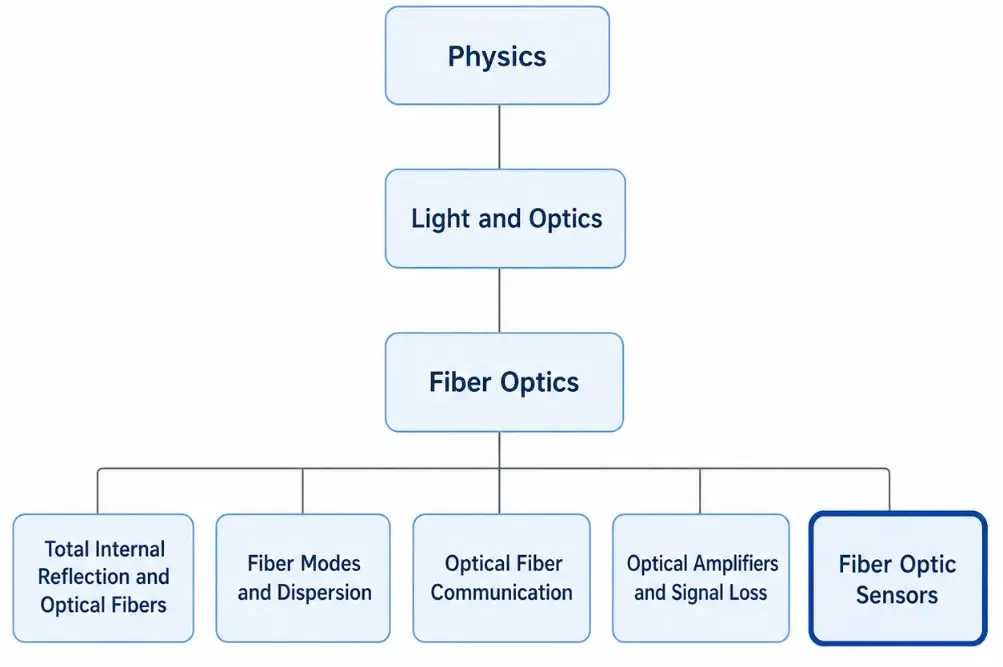
This tree chart shows the learning hierarchy for the Fiber Optics cluster within Physics and Light and Optics. The parent topic, Fiber Optics, branches into five related subpages: Total Internal Reflection and Optical Fibers, Fiber Modes and Dispersion, Optical Fiber Communication, Optical Amplifiers and Signal Loss, and Fiber Optic Sensors. The Fiber Optic Sensors page is highlighted to show the current position in the cluster, where students learn how optical fibers can become sensitive measuring devices for strain, temperature, vibration, pressure, chemical change, and structural monitoring.
What Fiber Optic Sensors REALLY Mean
A fiber optic sensor is not simply a fiber with a detector at the end. It is a measurement system in which light becomes a messenger. The fiber carries light into, through, or near the region being monitored. The physical condition of that region modifies the light in a measurable way. The detector then reads the optical change and converts it into useful data.
For example, when a bridge bends slightly under load, a fiber attached to the bridge may stretch by a tiny amount. That stretching can shift the wavelength reflected by a fiber Bragg grating. When a pipeline vibrates, sound waves may disturb the optical phase or backscattering pattern along a sensing fiber. When temperature changes, the refractive index and physical length of the fiber may change. These effects are small, but modern optical instruments can measure them very accurately.
The deeper idea is that a fiber optic sensor does not always measure a quantity directly. It often measures how light has been changed. The physical quantity is then inferred from calibration, modelling, and known optical behaviour. This is why fiber optic sensing connects optics, materials, electronics, signal processing, and engineering judgement.
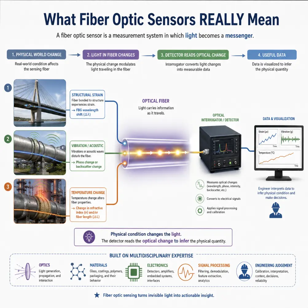
This educational illustration explains the real meaning of fiber optic sensing. It shows that a fiber optic sensor is a measurement system in which light acts as a messenger. Physical changes in the monitored environment, such as bridge strain, pipeline vibration, and temperature variation, modify the light travelling through the fiber. These changes may appear as wavelength shift, phase change, backscatter variation, or changes in refractive index and effective fiber length. An optical interrogator then reads the altered light, applies calibration and signal processing, and converts the result into useful data. The diagram also highlights the multidisciplinary nature of fiber optic sensing by linking optics, materials, electronics, signal processing, and engineering judgement.
Theoretical Framework: Phase Gating Expressions, Bragg Resonance Modulation, and Backscattering Moduli
To understand how light functions as an embedded structural monitor with complete quantitative rigor, undergraduate students must master the waveguide phase and spectral equations that govern optical modulation.
Interferometric Optical Path Length Modulation
In highly sensitive phase-based sensors, an outside strain or temperature shift changes the accumulated optical phase difference. The total phase φ of a light wave traveling through a fiber core section depends on the core’s physical length L and its effective refractive index n:
$$\phi = \frac{2\pi n L}{\lambda_0}$$Where λ0 represents the free-space wavelength of the injected light. When mechanical strain or a temperature flux alters the core, the total differential phase change Δφ is found by taking the derivative with respect to structural adjustments:
$$\Delta\phi = \frac{2\pi}{\lambda_0} \left( n \cdot \Delta L + L \cdot \Delta n \right)$$The term n · ΔL represents the physical elongation of the glass waveguide. The term L · Δn represents the photoelastic effect (for strain) or the thermo-optic effect (for temperature), where localized stress or thermal energy alters the material’s underlying index matrix. Because visible and near-infrared optical wavelengths are incredibly small, even a sub-nanometer change in physical path length produces a highly measurable shift in phase, enabling interferometric fiber systems to track minor structural vibrations with extreme precision.
Spectral Shifts in Fiber Bragg Gratings (FBGs)
Wavelength-based sensors eliminate the system drift found in simple intensity tracking by locking measurements to a narrow reflected spectrum. A fiber Bragg grating features a short, periodic modulation of the core’s refractive index. This micro-pattern acts as a selective mirror that reflects one specific wavelength, known as the Bragg resonance wavelength λB:
$$\lambda_B = 2 n_{\text{eff}} \Lambda$$Where neff is the effective refractive index seen by the guided mode and Λ is the physical period spacing of the grating pattern. Under an applied axial strain ε, the structural grating period elongates, shifting the target reflected wavelength by an amount ΔλB:
$$\frac{\Delta\lambda_B}{\lambda_B} = \left( 1 – p_e \right) \epsilon + \left( \alpha_{\Lambda} + \xi \right) \Delta T$$Where pe is the effective photoelastic constant of silica, αΛ is the thermal expansion coefficient of the glass substrate, and ξ represents the material’s thermo-optic coefficient. This relationship demonstrates that the reflected signal tracks both mechanical strain and ambient thermal shifts, requiring careful calibration to separate the overlapping parameters.
Basic Structure of a Fiber Optic Sensing System
A typical fiber optic sensing system has four main parts: a light source, an optical fiber or sensing element, an optical receiver or interrogator, and a data-processing system. The exact arrangement depends on the type of sensor, but the same general logic appears again and again.
Light Source: The light source may be a laser diode, broadband light source, superluminescent diode, or another optical emitter. Some sensors need a narrow, stable wavelength. Others need a broad spectrum so that wavelength shifts can be measured. The source must be chosen to match the sensing method.
Sensing Fiber or Sensing Element: The fiber may itself be the sensor, or it may only carry light to a separate sensing head. In some systems, the sensing element is a special structure written into the fiber, such as a fiber Bragg grating. In other systems, the entire fiber length acts as a distributed sensor.
Optical Receiver or Interrogator: The receiver measures the returning or transmitted light. In many fiber optic sensor systems, the receiver is called an interrogator because it sends light into the fiber, observes the optical response, and extracts the measured quantity.
Data Processing: The optical signal must be converted into meaningful information. This may involve wavelength tracking, intensity comparison, phase measurement, time-of-flight analysis, noise filtering, calibration curves, temperature compensation, or pattern recognition. This digital step connects hardware directly with the algorithms of Data Science and Analytics.
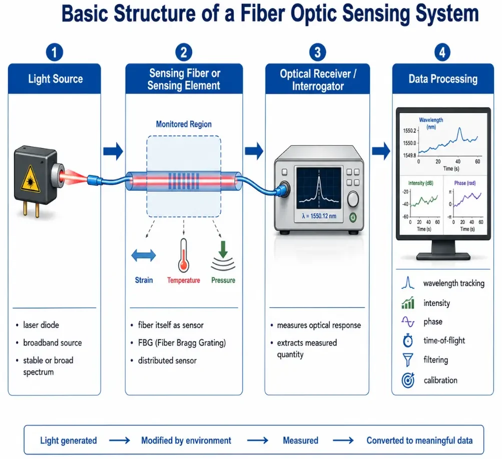
This diagram illustrates the basic structure of a fiber optic sensing system. It shows four main stages arranged in sequence: a light source, which launches light into the system; a sensing fiber or sensing element, where the environment modifies the light; an optical receiver or interrogator, which reads the returning or transmitted optical response; and a data-processing stage, which converts the optical signal into meaningful results. The sensing stage is shown responding to quantities such as strain, temperature, and pressure, while the data-processing stage highlights tasks such as wavelength tracking, intensity comparison, phase measurement, time-of-flight analysis, filtering, and calibration.
Intrinsic versus Extrinsic Fiber Optic Sensors
Fiber optic sensors are classified as intrinsic or extrinsic based on whether the glass waveguide acts as the active sensing medium or simply as a delivery channel.
Intrinsic Sensors: In an intrinsic configuration, the optical fiber itself changes its properties in response to the environment. The light remains safely inside the core throughout the run, but its intensity, phase, wavelength, or scattering pattern is modulated directly by outside environmental conditions. Examples include long-range distributed temperature lines and integrated core strain gauges.
Extrinsic Sensors: In an extrinsic sensor, the fiber functions strictly as a passive conduit, carrying light to and from an external sensing region. The actual light-matter interaction occurs outside the physical fiber boundary, such as inside a miniature cavity or off a moveable mechanical component. For example, a fiber tip might project light onto a diaphragm that flexes under pressure, and the system evaluates changes in the returning reflections.
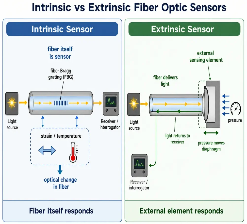
This educational illustration compares two main classes of fiber optic sensors. On the left, the intrinsic sensor is shown with the fiber itself acting as the sensing medium. The diagram uses a fiber Bragg grating example to show how strain or temperature changes the optical behavior inside the fiber, and the receiver or interrogator reads that change. On the right, the extrinsic sensor is shown with the fiber carrying light to an external sensing element, such as a pressure-sensitive diaphragm. The sensing action takes place outside the fiber, and the modified light returns through the fiber to the receiver. The comparison helps students understand the key difference between sensing within the fiber and sensing in a separate external element.
Classifying Modalities of Optical Sensing
Engineers leverage distinct physical changes inside a glass waveguide to isolate and measure specific target dimensions:
Intensity-Based Sensors: Track variations in total received light power. When a fiber experiences macro-bending stress or interacts with an absorbing chemical coating, the total light reaching the detector drops. While simple to build, these systems require careful management to ensure connection losses or lamp drift are not misinterpreted as sensing signals.
Interferometric Configurations: Compare phase differences between a reference path and an active sensing path using configurations like Mach-Zehnder, Michelson, Fabry-Pérot, or Sagnac loops. Sagnac fiber configurations form the basis of all modern optical gyroscopes, tracking angular rotation without any moving parts.
Distributed Fiber Optic Sensing (DFOS): Converts an entire fiber cable into a continuous tracking grid extending over many kilometers. By launching a fast pulse and tracking the arrival time of weak backscattered signals, the system maps out real-time anomalies along the line.
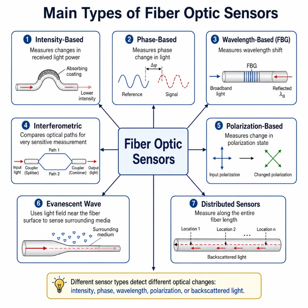
This diagram introduces the main types of fiber optic sensors in a simple visual overview. It shows intensity-based sensors that measure changes in received light power, phase-based sensors that detect phase shifts, wavelength-based sensors such as fiber Bragg grating sensors that measure wavelength shifts, interferometric sensors that compare optical paths, polarization-based sensors that detect changes in polarization state, evanescent wave sensors that use the light field near the fiber surface, and distributed sensors that measure conditions along an entire fiber length. The illustration helps students see that different sensing methods are based on different ways in which the light inside or near an optical fiber can be changed.
Scattering Mechanisms: Rayleigh, Raman, and Brillouin
Long-range distributed systems monitor continuous fiber lines by evaluating three core backscattering mechanisms:
- Rayleigh Backscattering: Arises from natural, microscopic index variations locked inside the silica structure during manufacturing. Analyzing this scattered light supports Distributed Acoustic Sensing (DAS) systems, which can detect structural movements, pipeline leaks, or security perimeter vibrations.
- Raman Backscattering: Produced by light interacting with internal molecular vibrations. Because the intensity of high-frequency anti-Stokes lines shifts with local heat, Raman scatter forms the foundation of Distributed Temperature Sensing (DTS) lines used for fire detection inside commercial tunnels.
- Brillouin Backscattering: Triggered by photon interactions with acoustic phonons (sound waves) moving through the glass grid. The resulting frequency shift responds directly to both mechanical tension and temperature changes, making it highly valuable for Distributed Strain Sensing (DSS) across major dams and railways.
Advantages of Fiber Optic Sensing
Fiber optic sensors are valuable because they offer advantages that are difficult to achieve with many electrical sensors.
Electromagnetic Immunity
Because the signal is carried by light rather than electrical current, fiber optic sensors are highly resistant to electromagnetic interference. This is useful near transformers, power lines, and high-voltage systems.Hazardous Zone Safety
Since fiber sensors do not need electrical power at the sensing point, they can be safer in explosive, flammable, or chemically harsh environments like oil wells and fuel repositories.Lightweight Integration
Optical fibers are thin and light. They can be embedded directly inside composite aerospace wings or composite structural frames without adding dead weight.Long-Range Integration
A single fiber can carry sensing information over long distances. Distributed sensing systems can monitor kilometres of infrastructure using a single fiber line.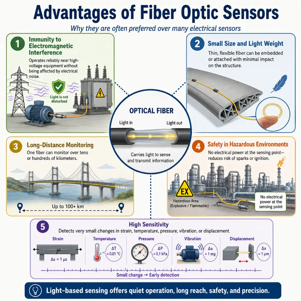
This infographic highlights the main advantages of fiber optic sensors. It shows that because they carry signals using light rather than electric current, they are highly resistant to electromagnetic interference and can operate reliably near power lines, motors, transformers, and other electrically noisy equipment. It also emphasizes their small size and light weight, which allow them to be embedded in structures or installed in narrow spaces. The infographic shows that a single optical fiber can monitor long distances, making it suitable for bridges, pipelines, and other large infrastructure systems. It also explains that fiber optic sensors are safer in hazardous environments because no electrical power is needed at the sensing point, reducing the risk of sparks in explosive or flammable locations. Finally, it illustrates their high sensitivity, showing that they can detect very small changes in strain, temperature, pressure, vibration, and displacement for precision monitoring and early warning.
Limitations and Operational Challenges
Fiber optic sensors are powerful, but they are not magic. A good sensor system requires correct design, installation, calibration, protection, and interpretation.
Interrogator Hardware Costs: While a strand of glass fiber is inexpensive, the specialized optoelectronic interrogators, stable tunable lasers, and cross-correlation spectrometers required to analyze the signals can be costly.
Cross-Sensitivity Anomalies: Many sensors respond to more than one influence. A fiber Bragg grating shifts its reflection peak under both axial tension and temperature fluctuations, meaning engineers must implement reference channels or temperature compensation loops to separate the parameters.
Physical Fragility Risks: Raw silica fiber cores can be broken by excessive shear stress, sharp bends, or crushing forces, requiring rugged protective buffers and specialized deployment routing in harsh field installations.
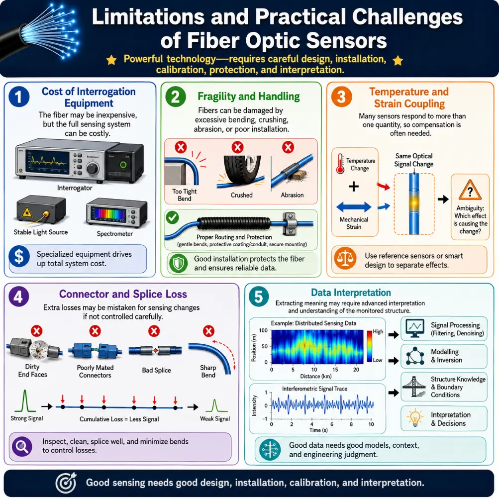
This infographic highlights the main limitations and practical challenges of fiber optic sensors. It shows that although the fiber itself may be inexpensive, the full sensing system can be costly because it may require specialised interrogators, stable light sources, spectrometers, or coherent detection equipment. It also illustrates the fragility of optical fibers, which can be damaged by excessive bending, crushing, abrasion, or poor installation, making careful routing and protection essential. Another section explains temperature and strain coupling, where the same optical signal may be influenced by more than one physical quantity, so compensation is often needed. The infographic also shows how dirty connectors, poor splices, and sharp bends can introduce unwanted losses that may be mistaken for sensing changes. Finally, it emphasizes that distributed and interferometric systems can produce large amounts of data, so extracting meaningful information often requires signal processing, modelling, filtering, and a good understanding of the monitored structure.
Real-World Application Domains
Optical fiber sensors are deployed across fields wherever lightweight, long-distance, or electrically quiet monitoring is required:
Structural Health Monitoring
FBG sensor arrays are multiplexed along bridge trusses and tunnels to capture real-time loading strains, mapping out micro-cracks before material failures expand.Geothermal and Energy Wells
Downhole fiber lines withstand severe pressures and corrosive chemicals to log high-temperature profiles inside deep oil wells and geothermal taps.Biomedical Diagnostics
Miniature fiber probes are built into flexible vascular catheters to monitor internal blood pressure and direct cardiac temperatures safely.Border and Pipeline Security
Distributed Acoustic Sensing lines buried along perimeters listen for tunneling, tracking ground vibrations to flag illegal border crossings or fence breaches.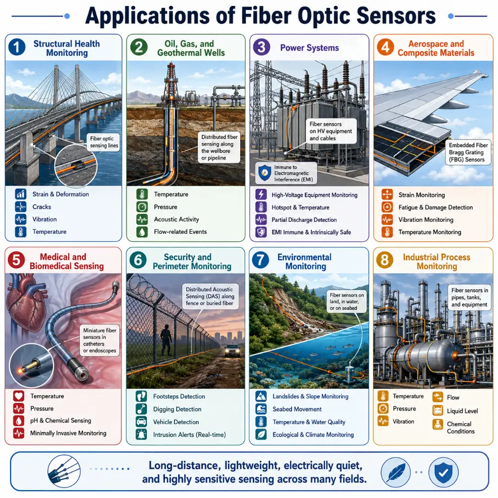
This infographic presents the main applications of fiber optic sensors across a wide range of real-world fields. It shows their use in structural health monitoring of bridges and infrastructure, in oil, gas, and geothermal wells for distributed sensing, and in power systems where immunity to electromagnetic interference is important. It also illustrates their role in aerospace and composite materials through embedded fiber Bragg grating sensors, in medical and biomedical sensing through miniature probes and catheters, and in security and perimeter monitoring using distributed acoustic sensing. Additional panels highlight environmental monitoring of land, water, and seabed conditions, as well as industrial process monitoring of temperature, pressure, vibration, flow, liquid level, and chemical conditions in plants and factories.
Common Conceptual Misunderstandings
The Amplitude Measurement Fallacy
Misconception: Fiber sensors only evaluate changes in total light power or basic brightness amplitude. Reality: Intensity tracking is sometimes used, but high-performance configurations track optical phase shifts, polarization rotations, and resonance wavelengths, which are highly stable against source power drops.The Passive Delivery Misconception
Misconception: The optical fiber serves strictly as a passive cable that carries data packets to an electrical sensor. Reality: In intrinsic and distributed systems, the glass material of the fiber core is the active sensor, responding directly to physical variations across its entire length.Interactive Quick Checks
Quick Check: Sensor Operations
1. In a fiber optic sensor, what usually carries the sensing information: electric current in a wire, or changes in light?
The sensing information is carried by changes in light. The change may appear as intensity, phase, wavelength, polarization, travel time, or backscattered light.
2. A fiber Bragg grating inside the fiber stretches when the monitored structure stretches. Is this closer to an intrinsic or extrinsic fiber optic sensor?
It is closer to an intrinsic sensor because the fiber itself contains the sensing element and responds directly to the physical change.
3. Why can a distributed fiber optic sensor identify where along the fiber an event occurred?
The system measures the time delay of returned light. Light returning from farther positions takes longer, so the delay can be converted into distance along the fiber.
Numerical Practice: Sensing Problems
Numerical Problems and Solutions
Problem 1: A fiber Bragg grating is structured with an effective mode index of neff = 1.45 and a baseline grating spacing period of Λ = 535 nm. Determine its primary Bragg resonance wavelength.
Apply the core Bragg expression:
$$\lambda_B = 2 n_{\text{eff}} \Lambda$$
$$\lambda_B = 2 \times 1.45 \times 535\text{ nm} = 2.90 \times 535\text{ nm} = 1551.5\text{ nm}$$Answer: The Bragg wavelength measures approximately 1552 nm.
Problem 2: An FBG temperature sensor exhibits a known calibration sensitivity of 10 pm/°C. During a process monitoring run, its reflected wavelength tracking peak shifts upwards by 80 pm. Calculate the temperature change.
Divide the measured wavelength shift by the system’s sensitivity parameter:
$$\Delta T = \frac{\Delta \lambda_B}{\text{Sensitivity}} = \frac{80\text{ pm}}{10\text{ pm/}^\circ\text{C}} = 8^\circ\text{C}$$Answer: The temperature change is exactly 8°C.
Problem 3: A test optical pulse is launched down a structural monitoring line. A Rayleigh backscatter reflection anomaly is registered back at the interrogator after a round-trip time delay of 20 μs. If light travels inside the fiber at a velocity of 2.0 × 10⁸ m/s, determine the physical distance to the event.
Because the measured time represents a full round-trip (to the event and back), divide the product of velocity and time by two:
$$d = \frac{v \cdot t}{2}$$Convert microseconds to base seconds ($20\text{ μs} = 20 \times 10^{-6}\text{ s}$):
$$d = \frac{(2.0 \times 10^8\text{ m/s}) \times (20 \times 10^{-6}\text{ s})}{2} = \frac{4000\text{ m}}{2} = 2000\text{ m}$$Answer: The event is located approximately 2000 m (or 2.0 km) away from the interrogator hardware.
Problem 4: An intensity-based macro-bend sensor transmits 5.0 mW of optical power when resting straight. When subjected to an external structural load, the received power drops to 3.5 mW. Calculate the percentage decrease in transmitted power.
Find the absolute drop in optical power:
$$\Delta P = P_{\text{straight}} – P_{\text{bent}} = 5.0\text{ mW} – 3.5\text{ mW} = 1.5\text{ mW}$$Divide this drop by the initial input baseline value to determine the percentage change:
$$\text{Percentage Decrease} = \left( \frac{1.5\text{ mW}}{5.0\text{ mW}} \right) \times 100\% = 0.30 \times 100\% = 30\%$$Answer: The transmitted power decreases by exactly 30%.
Problem 5: A fiber Bragg grating has neff = 1.46 and Λ = 530 nm. Calculate the Bragg wavelength.
Apply the core Bragg expression:
$$\lambda_B = 2 n_{\text{eff}} \Lambda$$
$$\lambda_B = 2 \times 1.46 \times 530\text{ nm} = 2.92 \times 530\text{ nm} = 1547.6\text{ nm}$$Answer: The Bragg wavelength is approximately 1548 nm.
Problem 6: An FBG temperature sensor shifts by 120 pm. If its temperature sensitivity is 10 pm/°C, find the temperature change.
Divide the measured wavelength shift by the system’s sensitivity parameter:
$$\Delta T = \frac{120\text{ pm}}{10\text{ pm/}^\circ\text{C}} = 12^\circ\text{C}$$Answer: The temperature change is exactly 12°C.
Problem 7: A reflected signal returns after 50 μs. If light travels in the fiber at 2.0 × 10⁸ m/s, find the distance to the reflecting point.
Because the measured time represents a full round-trip, divide the product of velocity and time by two:
$$d = \frac{v \cdot t}{2}$$Convert microseconds to base seconds ($50\text{ μs} = 50 \times 10^{-6}\text{ s}$):
$$d = \frac{(2.0 × 10^8\text{ m/s}) \times (50 \times 10^{-6}\text{ s})}{2} = \frac{10000\text{ m}}{2} = 5000\text{ m}$$Answer: The reflecting point is exactly 5.0 km away.
Problem 8: A fiber sensor receives 4.5 mW before a process starts and 3.6 mW after the process starts. What fraction of the original power remains?
Divide the final output power by the initial input level:
$$\text{Fraction Remaining} = \frac{3.6\text{ mW}}{4.5\text{ mW}} = 0.80$$Answer: A fraction of 0.80 (or 80%) of the original power remains.
Key Terms
- Fiber optic sensor
- A measurement system that uses changes in light travelling through or near an optical fiber to detect physical, chemical, biological, or environmental quantities.
- Intrinsic sensor
- A class of fiber sensor where the glass waveguide core itself serves as the active light-modulating sensing medium.
- Extrinsic sensor
- A sensor configuration where the fiber acts as a passive pipe, guiding light to and from an external sensing element.
- Fiber Bragg Grating (FBG)
- A microstructure inside a fiber core with a periodic refractive index pattern that reflects one specific wavelength of light.
- Distributed sensing
- A method that uses continuous backscattering profiles to turn an entire fiber cable length into a seamless, long-range measurement line.
- Cross-sensitivity
- An operational issue where a single optical parameter responds simultaneously to multiple environmental forces, such as temperature and mechanical strain.
External References
National Institute of Standards and Technology — Reference data detailing calibration methodologies, measurement science guidelines, and optical frequency standards.
SPIE Digital Library — Research literature databases covering optical waveguide manufacturing, laser testing setups, and fiber sensor systems.
Optica Publishing Group — Scientific journals cataloging developments in fiber Bragg gratings and evanescent wave biosensors.
IEEE Xplore Digital Library — Technical papers analyzing distributed acoustic sensing models and optoelectronic interrogator designs.
NASA Technical Reports Server — Engineering project reports analyzing embedded FBG sensors inside composite spacecraft panels and aircraft frames.
Summary
Fiber optic sensors use changes in light to measure changes in the physical world. Depending on the design, the sensor may measure intensity, phase, wavelength, polarization, travel time, or backscattered light. These optical changes can reveal strain, temperature, pressure, vibration, rotation, bending, chemical concentration, and other quantities. Some sensors are intrinsic, meaning the fiber itself acts as the sensing medium. Others are extrinsic, meaning the fiber carries light to and from a separate sensing region. Fiber Bragg gratings, interferometric sensors, evanescent wave sensors, and distributed sensing systems are among the most important types. The great strength of fiber optic sensing is that one thin optical fiber can measure conditions in places where ordinary electrical sensors may be too heavy, noisy, unsafe, or difficult to install. Yet successful sensing still depends on calibration, compensation, proper mounting, good optical design, and careful interpretation.
Reflection Question
If a single optical fiber can act as both a communication path and a sensing line, how might future cities, bridges, power systems, hospitals, and transport networks use hidden fibers not only to carry information, but also to quietly monitor their own condition?