Prepare for University Studies & Career Advancement
Diffraction and Resolution
Diffraction and resolution explain why light does not always behave like a perfectly sharp ray. When light passes through a narrow opening, around an edge, or through an optical instrument, it spreads out. This spreading is called diffraction. It is one of the clearest signs that light behaves as a wave.
This page belongs to the wider study of wave optics, which functions as a structural core inside the broader field of physical science. Diffraction connects closely with interference of light, because a diffraction pattern is formed when different parts of the same wavefront overlap and interfere. It also prepares students for diffraction gratings, where many regularly spaced openings or lines create sharp spectral patterns.
Diffraction also explains a deep limit in optical instruments. Even a perfect lens or mirror cannot produce an infinitely sharp image, because each point of light spreads into a small diffraction pattern. This is why resolution is not only a matter of better focusing or cleaner glass. It is also limited by wavelength and aperture size.
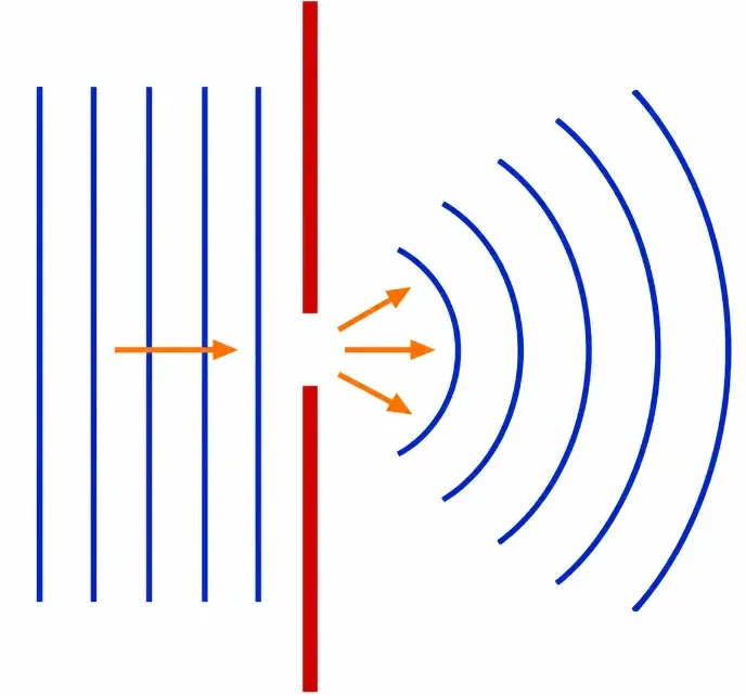
When plane light waves pass through a narrow slit, the transmitted wavefront spreads outward, showing diffraction as a clear sign of wave behaviour.
This simple diagram illustrates single-slit diffraction. Plane wavefronts approach a narrow opening in a barrier. After passing through the slit, the wavefronts spread outward as curved waves. The picture helps students see why light cannot always be treated as a perfectly sharp ray: when an opening is narrow enough, the wave nature of light becomes visible through diffraction.
The Evolutionary Path: History, System Barriers, and Foundry Paradigms
The progression of diffraction mechanics from a basic optical quirk into a rigorous branch of physical science transformed manufacturing limits across global computing industries.
The Historical Journey
The first systematic documentation of light bending around obstacles was published posthumously by Francesco Maria Grimaldi in 1663, who coined the term “diffraction.” In 1678, Christiaan Huygens formulated his wavefront propagation wavelets model, which was later mathematically synchronized with the principle of interference by Augustin-Jean Fresnel in 1818. This consolidated Huygens-Fresnel principle successfully predicted the unexpected bright spot at the center of a circular shadow—the Poisson spot—substantiating light’s wave profile. By 1873, Ernst Abbe established the fundamental resolution boundaries for traditional optical microscopes, paving the path for Lord Rayleigh’s 1896 formalization of the aperture criteria used across clinical imaging systems.
Contemporary Technical Hurdles
The most critical boundary in modern industrial foundries is bypassing the **Abbe diffraction limit** during high-density semiconductor fabrication tracks. When standard optical light masks drop to nanoscale dimensions, the spatial waves scatter automatically, blurring geometric edges and rendering traditional lenses incapable of focusing fine circuit patterns onto silicon wafers. This hardware bottleneck blocks further compaction of transistor tracks, demanding complex phase-shifting photolithography configurations to maintain phase coherence across dense feature tracks without triggering structural channel overlap.
Future Paradigms: Near-Field Sub-Wavelength Engineering and EUV Systems
Modern electronics processing overcomes classical diffraction boundaries by moving into extreme vacuum light tracks and deploying specialized near-field evanescent controllers:
Extreme Ultraviolet (EUV) Photolithography Foundries: To print nanoscale features far below old ultraviolet thresholds, manufacturing facilities deploy ultra-short 13.5 nm EUV laser systems. Operating within absolute vacuum lines to prevent atmospheric wave scattering, this technology maps complex silicon layouts with negligible diffraction distortion, scaling component densities directly.
Super-Resolution Near-Field Photonic Probes: Advanced diagnostic arrays utilize scanning near-field optical microscopes (SNOM) to capture non-propagating evanescent waves right at the sample interface boundary. By collecting these specialized signals before they travel and experience far-field diffraction spreading, systems extract high-resolution structural details far past old Abbe limitations.
Learning Pathway: Where Diffraction and Resolution Fit in Wave Optics
Diffraction and resolution sit at the point where wave behaviour becomes a practical limit. Interference shows how waves combine. Diffraction shows how waves spread. Resolution shows how this spreading affects what microscopes, telescopes, cameras, and other optical instruments can distinguish.
Explains why stable phase relationships matter and how interference fringes can be used for precision measurement.
Why Diffraction Happens
Light often seems to travel in straight lines because visible light has a very short wavelength. A typical wavelength of visible light is only a few hundred nanometres, while everyday openings such as windows, doorways, lens apertures, and ordinary holes are enormously larger. When the opening is much larger than the wavelength, the wave spreading at the edges is very small compared with the overall beam size. Most of the light continues forward, so the motion of light can be represented quite well by straight rays.
This is why the ray model of light is so useful. It helps us understand shadows, reflection, refraction, lenses, mirrors, and many ordinary optical instruments. The ray model is not completely wrong; it is a simplified picture that works when the wave nature of light is not strongly visible. In those cases, diffraction is still present, but it is usually too small to dominate what we see.
The situation changes when light passes through a small hole, a narrow slit, or an aperture whose size is not extremely large compared with the wavelength. The opening no longer allows a broad, nearly undisturbed wavefront to pass through. Instead, it cuts out only a limited part of the wavefront. Once the wavefront has been restricted in this way, the transmitted light cannot remain forever as a perfectly sharp beam with the exact shape of the opening.
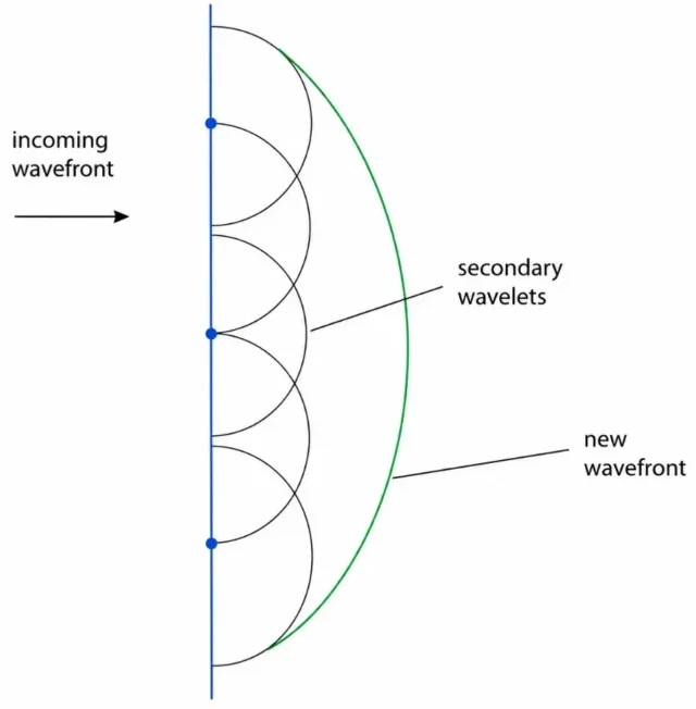
A helpful way to understand this is through Huygens’ principle. This principle says that each point on a wavefront can be treated as a small source of new secondary wavelets. The next wavefront is formed by the smooth outer envelope of these wavelets. In other words, a wavefront does not simply move forward as one rigid sheet. It can be imagined as being rebuilt continuously from many small wavelets.
This simple diagram illustrates Huygens’ principle: each point on an incoming wavefront produces a small secondary wavelet, and the outer envelope of these wavelets forms the new wavefront.
When a wide plane wave travels freely, many points across the wavefront produce secondary wavelets together. Because there are many neighbouring points, the sideways parts of the wavelets largely balance one another. Their combined outer envelope remains almost flat, so the wave continues mainly forward. This is why a broad light beam can look as if it travels in a straight line.
At a small opening, this balance is broken. The barrier blocks most of the original wavefront and allows only the part inside the opening to continue. The few points within the opening still produce secondary wavelets, but now there are no surrounding wavefront points on both sides to balance the sideways spreading. As a result, the transmitted wave spreads outward beyond the aperture.
This explains why a small hole does not produce a narrow cylinder of light that keeps the exact shape of the hole indefinitely. It also explains why a narrow slit does not produce a perfectly rectangular strip of light forever. The opening behaves less like a rigid stencil and more like a new wave source. A small circular hole sends wavefronts outward in many directions, while a narrow slit produces a fan-like spreading pattern.
The size of the opening compared with the wavelength is the key factor. If the opening is very wide compared with the wavelength, many parts of the wavefront pass through and the combined wave remains strongly forward-directed. If the opening is narrow, fewer parts of the wavefront pass through, and the sideways spreading becomes much more noticeable. This is why diffraction becomes stronger when the aperture becomes smaller.
Diffraction therefore does not mean that light stops moving forward. It means that the transmitted wave is not perfectly confined to the straight-edged region predicted by a simple ray diagram. The light still travels onward, but it also spreads into regions that would seem shadowed if light behaved only as sharply defined rays.
This spreading also leads to patterns of brightness and darkness. Different parts of the transmitted wavefront can reach the same point on a screen after travelling slightly different distances. Because of these path differences, the contributions may arrive in phase, out of phase, or somewhere in between. Where they reinforce, the intensity is higher. Where they cancel partly or strongly, the intensity is lower. A diffraction pattern is therefore produced by wave spreading together with interference among different parts of the same wavefront.
Key takeaway: Light appears to travel in straight lines when openings are much larger than its wavelength. But when an opening becomes small enough, only a limited part of the wavefront passes through. That restricted wavefront acts like a source of secondary wavelets, causing the light to spread instead of keeping the exact shape of the hole or slit.
Diffraction and Interference Are Closely Related
Diffraction should not be thought of as completely separate from interference. A diffraction pattern is formed because different parts of a wavefront reach the same point with different phases and then interfere.
In a single-slit experiment, light from different parts of the slit spreads out and overlaps on a screen. At some angles, the contributions reinforce and produce bright regions. At other angles, the contributions cancel and produce dark regions. This is why a single slit does not simply produce one bright rectangle. It produces a central bright maximum with weaker side maxima and dark minima.
In this sense, diffraction is interference within a spread-out wavefront. Interference of light often begins with two clearly separated paths. Diffraction often involves many paths across an aperture. The underlying wave idea is the same: phase relationships determine intensity.
Quick Check: Diffraction as Wave Spreading
Question 1: Why does light spread after passing through a narrow opening?
Light spreads because it behaves as a wave. When only part of the wavefront passes through an opening, that part spreads out beyond the aperture and overlaps with itself.
Question 2: When is diffraction easiest to notice?
Diffraction is easiest to notice when the opening or obstacle is comparable in size to the wavelength of the wave.
Question 3: Why is diffraction related to interference?
A diffraction pattern forms because light from different parts of the aperture reaches the same point with different phases. These contributions interfere, producing bright and dark regions.
Single-Slit Diffraction
A single slit provides one of the simplest ways to study diffraction. Suppose monochromatic light passes through a narrow slit of width a. Instead of forming a sharp image of the slit, the light spreads and forms a pattern on a distant screen.
The pattern has a broad central bright region called the central maximum. On both sides of it are weaker bright regions separated by dark minima. The central maximum is wider and brighter than the side maxima.
The dark minima occur when light from different parts of the slit cancels. For a single slit, the condition for dark minima is:
$$a \sin \theta = m\lambda$$
where a is the slit width, θ is the angle from the central direction, λ is the wavelength of light, and m = 1, 2, 3, … Notice that m = 0 is not used for a dark minimum, because the centre is a bright maximum.
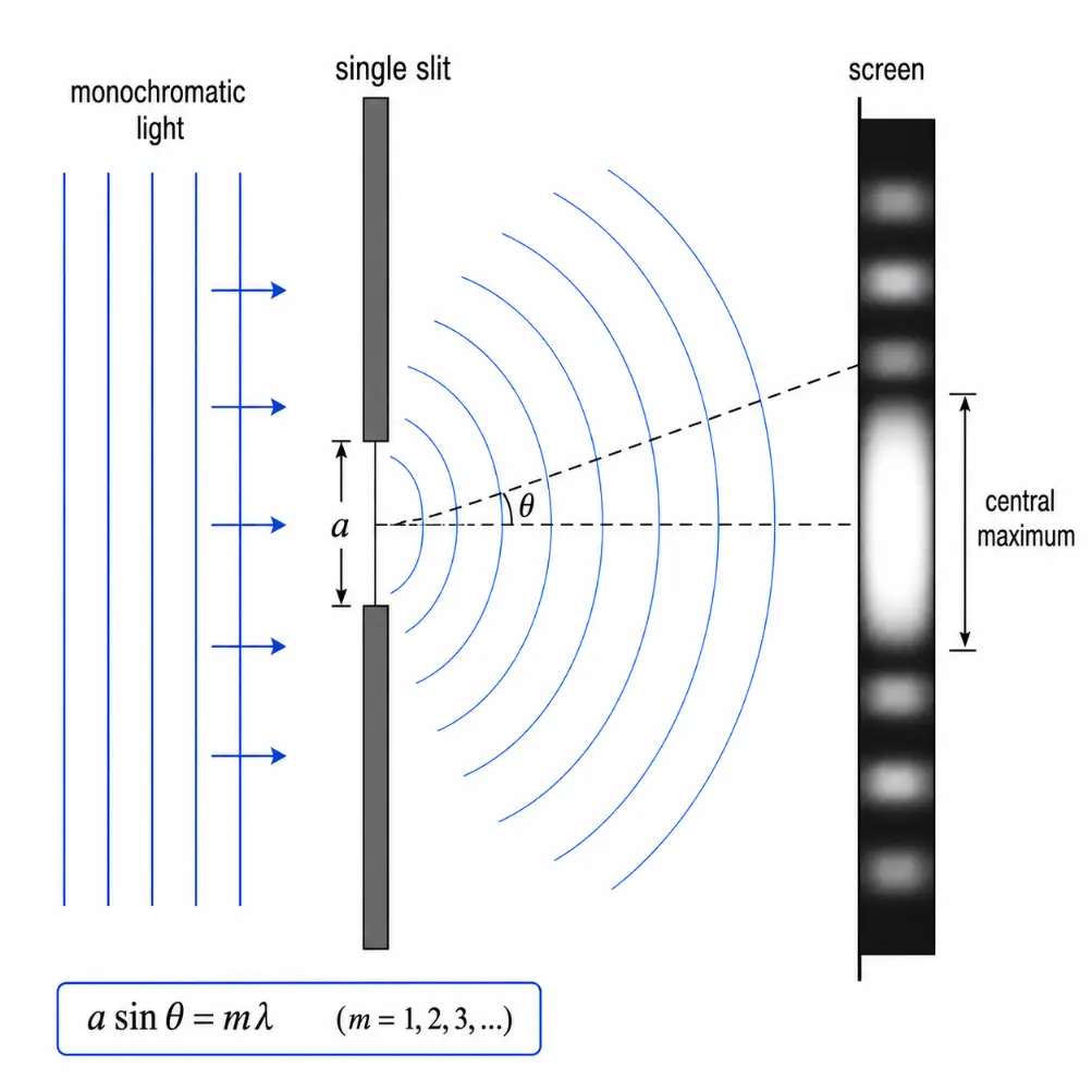
Monochromatic light spreads after passing through a narrow single slit, producing a broad central maximum and weaker side bright regions separated by dark minima.
This diagram illustrates single-slit diffraction. Plane wavefronts of monochromatic light approach a narrow slit of width a. After passing through the slit, the light spreads outward as curved wavefronts instead of continuing as a sharply defined beam. The angle θ is measured from the centre of the slit opening to a point away from the central direction. On the screen, the diffraction pattern shows a broad central maximum, with weaker bright regions above and below it. The equation a sin θ = mλ gives the directions of dark minima, where light from different parts of the slit cancels.
What the Single-Slit Formula Means
The equation \(a \sin \theta = m\lambda\) says that the directions of darkness depend on the ratio of wavelength to slit width. If the slit becomes narrower, the diffraction pattern spreads out more. If the wavelength becomes larger, the pattern also spreads out more.
This is one of the most important ideas in wave optics:
A narrower slit produces more spreading.
A wider slit produces less spreading.
A longer wavelength produces more spreading.
A shorter wavelength produces less spreading.
This rule appears again in optical resolution. A larger aperture reduces diffraction spreading and improves resolution. A shorter wavelength also improves resolution.
The Width of the Central Maximum
For a single slit, the first dark minima occur at:
$$a \sin \theta = \lambda$$
These first minima mark the approximate angular width of the central bright region. The central maximum extends from the first minimum on one side to the first minimum on the other side.
If the angle is small, then \(\sin \theta \approx \theta\) when θ is measured in radians. The first minimum is then approximately at:
$$\theta \approx \frac{\lambda}{a}$$
The full angular width of the central maximum is therefore approximately:
$$2\theta \approx \frac{2\lambda}{a}$$
This approximation is useful near the central direction. However, the exact angular condition \(a \sin \theta = m\lambda\) should be remembered because it is more fundamental.
From Diffraction to Resolution
Resolution is the ability to distinguish two nearby points as separate. Diffraction limits resolution because a point object is not imaged as a perfect point. Instead, it forms a small diffraction pattern.
For a circular aperture, such as a telescope objective or a camera lens, the diffraction pattern of a point source is called an Airy pattern. It consists of a central bright spot, called the Airy disk, surrounded by faint rings.
If two point sources are far apart, their Airy disks are separated and the two objects can be resolved. If the sources are too close, their Airy disks overlap strongly and the two objects blur into one.
This is why diffraction places a fundamental limit on sharpness. Even a perfectly made optical instrument cannot overcome diffraction unless the wavelength, aperture size, or imaging method changes.
The Rayleigh Criterion
The Rayleigh criterion gives a widely used estimate of when two point sources are just resolvable through a circular aperture. It says that two sources are just resolved when the central maximum of one Airy pattern falls near the first dark minimum of the other.
For a circular aperture, the angular resolution is approximately:
where \(\theta_R\) is the smallest angular separation that can be resolved, λ is the wavelength of light, and Dap is the diameter of the aperture.
A smaller value of \(\theta_R\) means better angular resolution. The equation shows two important ways to improve resolution:
Use a shorter wavelength λ.
Use a larger aperture diameter Dap.
This is why large telescopes can resolve finer astronomical detail than small telescopes, and why shorter-wavelength imaging can reveal smaller structures when other conditions allow.
Quick Check: Resolution and Aperture Size
Question 1: In the Rayleigh criterion, what happens to angular resolution when the aperture diameter increases?
The angular resolution improves. Since \(\theta_R \approx 1.22\frac{\lambda}{D_{\text{ap}}}\), increasing Dap makes \(\theta_R\) smaller, so closer objects can be distinguished.
Question 2: Why does a shorter wavelength improve resolution?
A shorter wavelength diffracts less through the same aperture. This produces a smaller diffraction pattern and makes it easier to distinguish nearby details.
Question 3: Does better focusing alone remove the diffraction limit?
No. Good focusing is important, but diffraction remains even in a perfect optical system. The diffraction limit comes from the wave nature of light.
Resolution in Microscopes
Microscopes also face diffraction limits. In microscopy, resolution is often expressed as the smallest distance between two points that can still be distinguished. A common approximate form is:
$$r \approx 0.61\frac{\lambda}{\text{NA}}$$
where r is the smallest resolvable distance, λ is the wavelength, and NA is the numerical aperture of the objective lens.
The numerical aperture measures how much light the objective can collect from the specimen. A higher numerical aperture means the microscope can collect light over a wider cone of angles. This improves resolution.
The equation shows that microscope resolution improves when:
The wavelength is shorter.
The numerical aperture is larger.
The optical system is well aligned and well corrected.
This is why high-resolution microscopy often uses carefully designed objective lenses, immersion media, controlled illumination, and sometimes shorter wavelengths or advanced imaging techniques.
Diffraction-Limited Images
An image is called diffraction-limited when its sharpness is limited mainly by diffraction rather than by poor focusing, lens defects, vibration, atmospheric turbulence, or sensor quality.
This is actually a sign of a very good optical system. It means the instrument is performing so well that the remaining blur is caused by the unavoidable wave spreading of light itself.
In astronomy, the atmosphere often prevents ground-based telescopes from reaching their ideal diffraction limit. In microscopy, sample preparation, lens quality, illumination, and detector performance can also affect resolution. But the diffraction limit remains the basic physical reference point.
Why Bigger Apertures Improve Resolution
A larger aperture collects light from a wider part of the incoming wavefront. This reduces the angular size of the diffraction pattern. In a telescope, a larger mirror or lens can therefore separate objects with smaller angular separation.
This is why telescope size matters. A larger aperture does not merely make faint objects brighter by collecting more light. It also improves the theoretical ability to distinguish fine detail.
The same idea appears in many optical systems. Camera lenses, microscope objectives, antennas, and even radio telescopes all face diffraction-related limits. The details differ, but the principle is the same: aperture size and wavelength strongly affect resolution.
Why Shorter Wavelengths Improve Resolution
Shorter wavelengths diffract less through the same aperture. This means that shorter-wavelength light can produce a smaller diffraction pattern and resolve finer details.
For visible light, blue light has a shorter wavelength than red light, so it can in principle provide slightly better resolution. However, practical optical systems must also deal with absorption, scattering, aberration, detector sensitivity, and material limitations.
Outside visible light, the same principle explains why X-rays and electron beams can reveal much smaller structures than ordinary visible light. Their shorter effective wavelengths allow much finer spatial detail, although the instruments and physical interactions are very different.
Airy Disks and Point Images
A point source imaged through a circular aperture forms an Airy pattern. The central bright spot is the Airy disk, and the faint surrounding rings are caused by diffraction.
Two point sources can be resolved only if their Airy patterns are sufficiently separated. If the central bright regions overlap strongly, the eye or detector may see only one blurred spot. If the overlap is moderate, the two sources may be just resolved. If the patterns are well separated, the two sources are clearly resolved.
This is important because many real images can be understood as collections of point-like contributions. The sharper each point image is, the more detail the final image can contain.
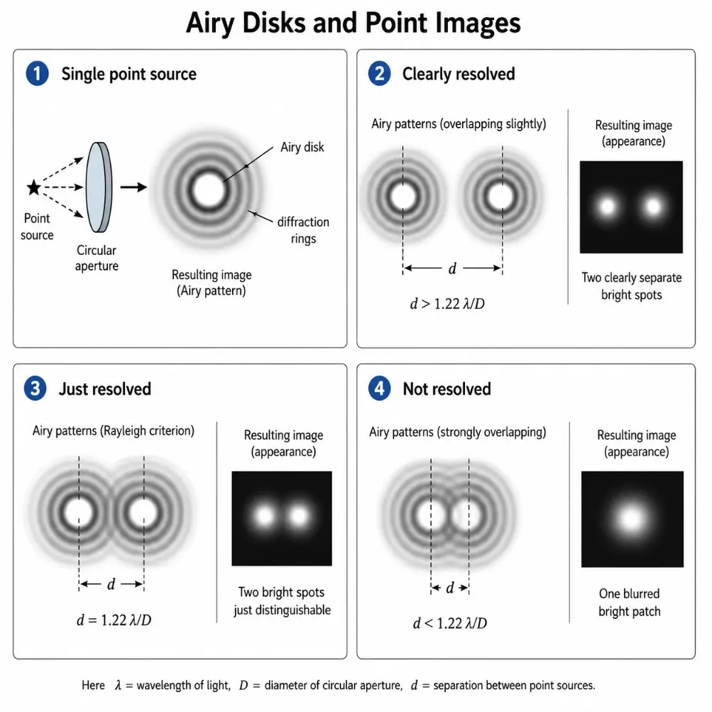
A point source imaged through a circular aperture forms an Airy disk with surrounding diffraction rings. Two point sources can be resolved only when their Airy patterns are sufficiently separated.
This infographic explains how diffraction affects the imaging of point sources. A single point source does not form a perfect point image after passing through a circular aperture; instead, it forms an Airy pattern with a bright central disk and faint surrounding rings. The diagram then compares three cases for two point sources: clearly resolved, just resolved, and not resolved. When the Airy patterns are well separated, two bright spots are seen clearly. When they overlap moderately, the two points are just distinguishable according to the Rayleigh criterion. When they overlap strongly, the detector sees only one blurred bright patch. This helps students understand why resolution is limited by diffraction, not just by lens quality or magnification.
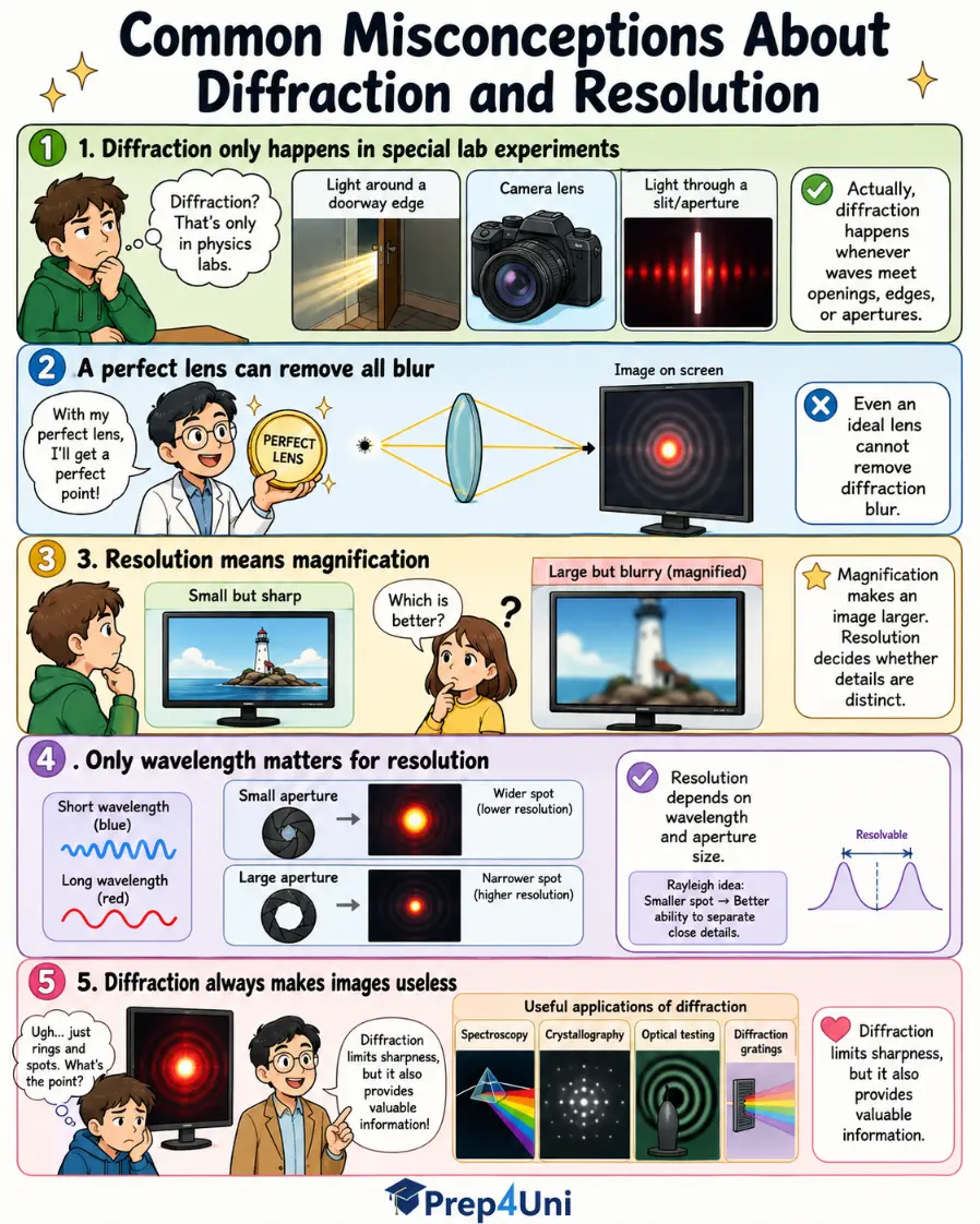
Common Misconceptions About Diffraction and Resolution
Misconception 1: Diffraction Only Happens in Special Laboratory Experiments
Diffraction happens whenever waves encounter openings, edges, apertures, or obstacles. It may be too small to notice in everyday situations, but it is always present in optical systems.
Misconception 2: A Perfect Lens Can Remove All Blur
A perfect lens can remove many optical defects, but it cannot remove diffraction. Even an ideal lens forms a diffraction pattern for each point source.
Misconception 3: Resolution Means Magnification
Magnification makes an image larger. Resolution determines whether fine details can be distinguished. A highly magnified but poorly resolved image is just a larger blur.
Misconception 4: Only Wavelength Matters for Resolution
Wavelength is important, but aperture size is also crucial. For circular apertures, \(\theta_R \approx 1.22\frac{\lambda}{D_{\text{ap}}}\), so resolution depends on both λ and Dap.
Misconception 5: Diffraction Always Makes Images Useless
Diffraction limits sharpness, but it also provides useful information. Diffraction patterns are used in spectroscopy, crystallography, optical testing, diffraction gratings, and many scientific instruments.
This comic-style infographic clears up five common misconceptions about diffraction and resolution, showing that diffraction is always present in optical systems and that good imaging depends on both wave behaviour and instrument design.
This educational comic presents five common misconceptions about diffraction and resolution in a lively, student-friendly format. It explains that diffraction is not limited to laboratory experiments but occurs whenever waves meet openings, edges, or apertures. It shows that even a perfect lens cannot remove diffraction blur completely, because diffraction is a fundamental wave effect. The comic also distinguishes magnification from resolution by showing that making an image larger does not automatically make it sharper. Another panel explains that resolution depends not only on wavelength but also on aperture size, so both factors matter in optical instruments. The final panel shows that diffraction does not merely limit image sharpness; it also provides useful information in fields such as spectroscopy, crystallography, optical testing, and diffraction gratings. Overall, the comic helps students understand that diffraction and resolution are not just obstacles in optics, but important ideas that reveal how light behaves and how optical systems work.
Quick Check: Misconceptions About Resolution
Question 1: Is magnification the same as resolution?
No. Magnification makes an image larger, while resolution determines whether fine details can be distinguished. A large image can still be blurry.
Question 2: Can a perfect lens completely remove diffraction blur?
No. Diffraction blur remains even in a perfect lens because it comes from the wave nature of light, not from manufacturing defects.
Question 3: Why can a larger telescope resolve finer detail?
A larger aperture produces a smaller diffraction pattern. This allows the telescope to distinguish objects with smaller angular separation.
Applications of Diffraction and Resolution
Diffraction and resolution appear in many technologies because they determine how sharply waves can reveal structure. They matter whenever light is focused, measured, separated, or used to form an image.
Telescopes
Telescopes use large apertures to collect light and improve angular resolution. Diffraction determines the finest detail an ideal telescope can distinguish. In practice, atmospheric turbulence, mirror quality, and detector performance also matter.
Microscopes
Microscope resolution is limited by wavelength and numerical aperture. Higher numerical aperture and shorter wavelength can improve resolution, but practical design and sample conditions also play major roles.
Camera and Imaging Systems
Camera lenses are affected by diffraction, especially at very small aperture settings. Closing the aperture can improve depth of field, but too small an aperture increases diffraction blur. Good imaging requires a balance between focus, aperture, lens quality, and sensor performance.
Laser Beams
Laser beams spread because of diffraction. A beam with a finite width cannot remain perfectly parallel forever. Beam divergence depends on wavelength and beam diameter.
Optical Fibres
Diffraction and wave behaviour affect how light is guided, coupled, and transmitted in optical fibres. Fibre core size, wavelength, and mode structure all influence optical performance.
Spectroscopy and Diffraction Gratings
Diffraction is used deliberately in diffraction gratings to separate light into different wavelengths. This makes diffraction essential in spectroscopy, chemical analysis, astronomy, and laser measurement.
Study Tips for Diffraction and Resolution
Remember that diffraction is wave spreading caused by apertures, edges, or obstacles.
Do not confuse diffraction with refraction. Refraction is bending caused by a change in wave speed; diffraction is spreading caused by wavefront restriction.
For a single slit, use \(a \sin \theta = m\lambda\) for dark minima, with m = 1, 2, 3, …
For circular apertures, use \(\theta_R \approx 1.22\frac{\lambda}{D_{\text{ap}}}\) as the Rayleigh angular resolution estimate.
Remember that resolution improves when wavelength decreases or aperture size increases.
Do not treat magnification as resolution. Enlarging a blurred image does not create new detail.
Review Questions
Question 1: What is diffraction?
Answer: Diffraction is the spreading of waves when they pass through an opening, around an edge, or past an obstacle.
Question 2: Why does diffraction show that light behaves as a wave?
Answer: Diffraction involves spreading and interference of wavefronts, which are wave behaviours. A purely ray-like model cannot fully explain diffraction patterns.
Question 3: What is the condition for dark minima in single-slit diffraction?
Answer: The dark minima occur when \(a \sin \theta = m\lambda\), where m = 1, 2, 3, …
Question 4: What is resolution?
Answer: Resolution is the ability to distinguish nearby objects, points, or details as separate.
Question 5: Why does diffraction limit resolution?
Answer: Diffraction spreads the image of each point into a finite pattern. If two such patterns overlap too much, the two points cannot be clearly distinguished.
Question 6: What does the Rayleigh criterion estimate?
Answer: It estimates the smallest angular separation at which two point sources can be just resolved through a circular aperture.
Question 7: Why does a larger aperture improve resolution?
Answer: A larger aperture reduces the angular spread of the diffraction pattern, allowing closer details to be distinguished.
Question 8: Why is magnification alone not enough for a good image?
Answer: Magnification enlarges the image, but resolution determines whether fine details are actually present. Enlarging a blurred image does not restore lost detail.
Comprehensive Numerical Problems with Solutions
Light of wavelength 500 nm passes through a single slit of width 0.10 mm. Find the angle of the first dark minimum.
Solution:
Apply the single-slit dark fringe condition expression:
$$a \sin \theta = m\lambda$$
For the first dark minimum, substitute \(m = 1\), isolating the spatial angle parameter:
$$\sin \theta = \frac{\lambda}{a}$$
Convert standard configuration values to meters metrics (\(\lambda = 500 \times 10^{-9}\ \text{m}\), \(a = 0.10 \times 10^{-3}\ \text{m}\)):
Answer: The first dark minimum lands at approximately 0.0050 radians (or 0.286°).
A deep-space telescope features an aperture diameter of 1.0 m. If it monitors an incoming target wavelength of 500 nm, estimate its diffraction-limited angular resolution.
Answer: The calculated angular resolution limit evaluates to precisely 6.1 × 10⁻⁷ radians.
An advanced optical microscope runs using a wavelength parameter of 450 nm alongside a lens numerical aperture index tracking at NA = 0.90. Estimate the minimum resolvable distance.
Solution:
Apply the structural lateral microscope resolution expression:
$$r \approx 0.61\frac{\lambda}{\text{NA}}$$
Substitute metrics straight into the fraction layout:
Answer: The smallest spatial resolvable distance checks out at precisely 305 nm.
Two separate tracking telescopes capture identical light wavelengths. Telescope A incorporates an aperture size measuring 0.25 m, while Telescope B utilizes an objective array diameter scaling to 1.0 m. Evaluate which system delivers a superior diffraction-limited angular resolution.
Solution:
The Rayleigh expression dictates that resolution properties map inversely relative to objective dimension profiles:
Because the aperture variable sits inside the denominator track, a larger physical diameter minimizes the output angular separation parameter value (\(\theta_R\)), generating sharper spatial definition metrics. Since Telescope B features a 1.0 m track compared to Telescope A’s 0.25 m limit, it establishes tighter diffraction parameters.
Answer: Telescope B delivers a superior diffraction-limited angular resolution due to its larger aperture system footprint.
Frequently Asked Questions
Question 1: What is diffraction of light?
Answer: Diffraction of light is the spreading of light waves when they pass through an opening, around an edge, or past an obstacle.
Question 2: Why does a narrower slit produce more diffraction?
Answer: A narrower slit restricts the wavefront more strongly. This causes the transmitted wave to spread out more after passing through the opening.
Question 3: What is the difference between diffraction and interference?
Answer: Interference usually refers to the combination of waves from different paths or sources. Diffraction refers to wave spreading caused by an aperture or obstacle. A diffraction pattern is produced by interference among different parts of a spread-out wavefront.
Question 4: What does resolution mean in optics?
Answer: Resolution is the ability of an optical system to distinguish two nearby objects or details as separate.
Question 5: Why is there a diffraction limit?
Answer: There is a diffraction limit because each point of light forms a finite diffraction pattern instead of a perfect point. When two such patterns overlap too much, the details cannot be separated.
Question 6: How can optical resolution be improved?
Answer: Resolution can be improved by using shorter wavelengths, larger apertures, higher numerical aperture in microscopy, better alignment, and advanced imaging methods.
Question 7: Is a diffraction-limited instrument poor quality?
Answer: No. A diffraction-limited instrument is usually very good. It means the main remaining limit is the unavoidable wave nature of light rather than defects in the instrument.
Question 8: Why are large telescopes useful?
Answer: Large telescopes collect more light and also reduce diffraction spreading. This improves their ability to detect faint objects and resolve fine angular detail.
External References
The following external references provide additional background from scientific, institutional, or reference sources. They are included for wider reading and do not replace the explanations on this page.
Diffraction is the spreading of light when a wavefront passes through an opening, around an edge, or past an obstacle. It becomes especially important when the aperture or obstacle is small enough for wave effects to be noticeable.
In a single-slit pattern, dark minima occur when \(a \sin \theta = m\lambda\), where m = 1, 2, 3, … This relationship shows why narrower slits and longer wavelengths produce greater spreading.
Resolution is the ability to distinguish nearby details as separate. Diffraction limits resolution because each point image spreads into a finite pattern. For a circular aperture, the Rayleigh criterion gives \(\theta_R \approx 1.22\frac{\lambda}{D_{\text{ap}}}\), showing that larger apertures and shorter wavelengths improve angular resolution.
Diffraction and resolution therefore reveal a powerful lesson: light does not merely illuminate objects. Its wave nature sets the limits of what can be seen, measured, and separated.
Reflection Question
If increasing magnification cannot recover details lost to diffraction, what does this tell us about the difference between making an image larger and truly seeing more information?