
Overview
This topic explores how objects interact through forces and how these forces produce both linear and rotational effects. Understanding forces and moments is essential for analyzing structures, machines, and motion in physics and engineering contexts.
Contents
- Types of forces
- Hooke’s Law and Elastic Forces
- Moment and torque
- Couples and the Principle of Moments
- Equilibrium Conditions
Learning Outcomes
By the end of this section, students should be able to:
- Describe forces on masses, charges, and currents in various fields
- Understand forces such as normal, frictional, buoyant, and viscous
- Apply Hooke’s Law: F = k × x
- Define and apply moment of a force and torque
- Understand the concept of a couple
- Apply the principle of moments and define the centre of gravity
- Analyze equilibrium using free-body diagrams and vector methods
1. Types of Forces
Contact forces (require touching):
- Normal force — acts perpendicular to the surface; balances compression (e.g., table on book).
- Friction — opposes relative motion along the surface; kinetic: fk = μk × N, static: fs ≤ μs × N.
- Tension — pull transmitted by an ideal (massless, inextensible) string; same magnitude along the string.
- Spring force — linear elastic restoring force: F = k × x (toward equilibrium; k in N·m-1).
Non-contact (field) forces (act at a distance):
- Gravitational force — attraction between masses: F = G × (m1 × m2) / r2 (near Earth’s surface: weight W = m × g).
- Electrostatic force — between charges: F = k × (|q1 × q2|) / r2 (repel/attract depending on signs).
- Magnetic force — on a moving charge: F = q × v × B × sin(θ) (or on a wire F = I × L × B × sin(θ)).
- Buoyant force — upward fluid force: Fb = ρ × g × Vdisp (Archimedes’ principle).
- Viscous/drag force — resistance in fluids; low speed: F ∝ v (e.g., 6 × π × η × r × v); high speed: F ∝ v2.
Answer: Weight W = m × g acting downward; normal reaction N acting upward. At rest, N = W = 2 × 9.81 ≈ 19.6 N, so ∑ Fy = 0.
A) Friction B) Tension C) Buoyant force D) Gravitational force
Answer: D) Gravitational force. It acts through a field without physical contact; the others require a surface or medium.
Tip: When drawing a free-body diagram (FBD), show each force as an arrow from the object’s centre; label magnitudes/angles and use up to two axes so you can write ∑ Fx = 0, ∑ Fy = 0 (and ∑ M = 0 for rotation) clearly.
2. Moment and Torque
What is a moment? The moment of a force (turning effect) about a pivot measures how strongly the force tends to rotate an object.
- Scalar (perpendicular) definition: For a force applied perpendicularly at a distance r from the pivot, M = F × r with SI unit N·m.
- General (angled) case: When the force makes an angle θ to the lever arm:M = F × r × sin(θ) or M = F⊥ × rwhere F⊥ = F × sin(θ) is the component of the force perpendicular to the lever arm.
- Vector definition (torque): τ = r × F; |τ| = r × F × sin(θ). Direction given by the right-hand rule (thumb = τ, fingers curl from r to F).
- Units: Newton–metre (N·m). Moments/torques are not “joules” even though 1 N·m = 1 J dimensionally; energy is a scalar work quantity, torque is an axial pseudovector quantity.
- Sign convention: In 2D statics, take counter-clockwise positive (CCW +), clockwise negative (CW −). Be consistent across the page.
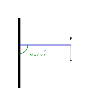
Worked Example (perpendicular force):
A 10 N force is applied perpendicularly at 0.5 m from a hinge.
M = F × r = 10 × 0.5 = 5.0 N·m (CCW if force tends to rotate counter-clockwise).
Worked Example (angled force):
A 20 N force acts at 30° to a spanner of length 0.40 m.
M = F × r × sin(θ) = 20 × 0.40 × sin(30°) = 20 × 0.40 × 0.5 = 4.0 N·m.
Only the perpendicular component F⊥ = 20 × sin(30°) = 10 N produces rotation; the along-spanner component does not contribute to moment.
Answer: M = F × r = 12 × 0.25 = 3.0 N·m.
Answer: τ = F × d ⇒ d = τ / F = 10 / 20 = 0.50 m.
SEO note for learners: Engineers often search “moment vs torque,” “lever arm,” and “right-hand rule.” Remember: moment is the turning effect; torque is the vector form τ = r × F; use M = F × r × sin(θ) for angled forces, and N·m as the SI unit.
3. Couples and the Principle of Moments
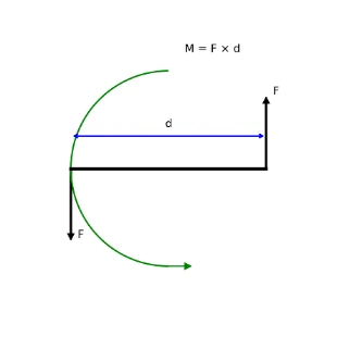
Couple:
- Two equal and opposite forces acting on different lines of action.
- Produces pure rotation (no net force, only turning effect).
Principle of Moments:
- For an object in rotational equilibrium: Sum of clockwise moments = Sum of anticlockwise moments.
- The diagram below illustrates the moment due to two equal forces F acting at distance D apart in opposite directions, forming a pure couple.
Example:
A uniform beam is balanced on a pivot. A 20 N weight is 1.5 m from the pivot on one side. What force must balance it 1 m from the pivot on the other side?
Clockwise Moment = 20 × 1.5 = 30 N·m
Let force F × 1 = 30 ⇒ F = 30 N
Answer: Moment of a couple = One force × Distance between forces = 15 N × 0.4 m = 6 N·m.
Answer: Clockwise moment = 30 N × 1.2 m = 36 N·m. To balance: Anticlockwise moment = W × 0.8 m ⇒ W = 36 / 0.8 = 45 N.
4. Equilibrium Conditions
Translational Equilibrium (no net force):
- Object remains at rest or moves with constant velocity (Newton’s First Law).
- In 2D: ∑ Fx = 0, ∑ Fy = 0. In 3D, also ∑ Fz = 0.
Rotational Equilibrium (no net moment/torque):
- No angular acceleration; object does not start/stop spinning.
- About any chosen pivot: ∑ M = 0.
Free-Body Diagrams (FBDs):
- Show the body as a simple shape (point/box/beam) and draw all external forces acting on it.
- Label magnitudes and directions; choose and mark a sign convention for moments (e.g., counter-clockwise +).

Friction models (useful in FBDs):
- Static friction (no slip): |f| ≤ μs × N (at impending motion: f = μs × N).
- Kinetic friction (sliding): fk = μk × N opposing motion.
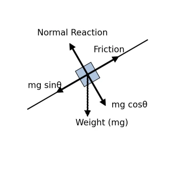
Inclined Plane Decomposition (angle θ to horizontal):
- Weight: m × g acts vertically downward.
- Components along/normal to plane: m × g × sin(θ) (down the plane), m × g × cos(θ) (into the plane).
- Normal reaction (no lift-off): N = m × g × cos(θ).
- If at rest (no slip): ∑ Fparallel = 0 ⇒ f = m × g × sin(θ) with |f| ≤ μs × N.
Beam Equilibrium (supports & moments):
A beam is in equilibrium when both translation and rotation balance: ∑ Fx = 0, ∑ Fy = 0, ∑ M = 0.
For a simply supported beam with reactions RA, RB, and a point load P at distance a from support A:
∑ Fy = 0 ⇒ RA + RB – P = 0 ⇒ RA = P – (P × a) / L = P × (1 – a / L)

Worked Example (Ladder idea, FBD thinking):
A ladder leans against a rough wall and rests on a rough floor. Draw the FBD: weight m × g at the ladder’s centre, normal reactions at wall and floor, and friction forces at both contacts opposing possible slip. Apply ∑ Fx = 0, ∑ Fy = 0, ∑ M = 0 about a convenient pivot to find unknown reactions. Check that friction forces obey |f| ≤ μ × N.
Answer: Forces: applied F (forward), friction fk (back), weight m × g (down), normal N (up). Since speed is constant: ∑ Fx = 0 ⇒ F – fk = 0; ∑ Fy = 0 ⇒ N – m × g = 0; fk = μk × N.
A) ∑ F ≠ 0 and ∑ M = 0 B) ∑ F = 0 and ∑ M = 0
C) ∑ F = 0 and ∑ M ≠ 0 D) ∑ F ≠ 0 and ∑ M ≠ 0
Answer: B) ∑ F = 0 and ∑ M = 0. Complete static equilibrium requires zero net force and zero net moment.
Some Interesting Examples
Example 1: Equilibrium of Forces — Vector Method
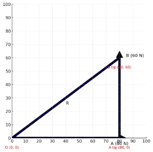
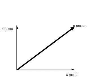
Problem. Two concurrent forces act at point O: A = 80 N directed horizontally to the right, and B = 60 N directed vertically upward. Find the single reaction force R (magnitude and direction) which, when applied at O, will keep the point in equilibrium (∑ F = 0).
Section 1 — Graphical (tip-to-tail) vector addition
- From O, draw vector A to the right (length proportional to 80 N).
- From the tip of A, draw vector B upward (length proportional to 60 N).
- The closing vector from the tip of B back to O is the reaction R, satisfying A + B + R = 0 ⇒ R = −(A + B).
Section 2 — Resolved-component (analytic) method
- Resolve forces into Cartesian components (+x right, +y upward): A = (80, 0) N, B = (0, 60) N.
- Resultant to oppose: A + B = (80, 60) N ⇒ R = −(A + B) = (-80, -60) N.
- Magnitude of reaction: |R| = √((-80)2 + (-60)2) = √(6400 + 3600) = √(10000) = 100 N.
- Direction of reaction: θR = arctan(Ry / Rx) = arctan(-60 / -80). Since Rx < 0 and Ry < 0 (third quadrant), add 180°: θR = 180° + 36.87° = 216.87° (or 36.9° below the -x direction).
Example 2: Centre of Gravity (Barycentre) of the Sun–Earth–Moon System
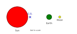
Problem. Three bodies lie approximately on a line: Sun (M⊙ = 1.989 × 1030 kg at x = 0), Earth (ME = 5.972 × 1024 kg at x = 1.496 × 10¹¹ m), and Moon (Mm = 7.347 × 10²² kg at x = 1.49984 × 10¹¹ m).
1D Barycentre Formula: xCG = (∑ Mi × xi) / (∑ Mi)
- Total mass: Mtot = 1.989006045 × 1030 kg.
- Weighted sum of positions: ∑ Mi × xi ≈ 9.044305245 × 1035 kg·m.
- Centre of gravity: xCG = 9.044305245 × 1035 / 1.989006045 × 1030 ≈ 4.55 × 10⁵ m (455 km from the Sun’s centre, deep inside the Sun).
Example 3: Maximum Incline Before Sliding
Problem. A box of mass m = 10 kg rests on a rough plane with static friction coefficient μ = 0.20. What is the largest angle θmax for which the box does not slide?
- Resolve forces: Wparallel = m × g × sin(θ), Wnormal = m × g × cos(θ), fmax = μ × m × g × cos(θ).
- Limiting equilibrium balance: m × g × sin(θ) = μ × m × g × cos(θ).
- Solve for angle: tan(θmax) = μ = 0.20 ⇒ θmax = arctan(0.20) ≈ 11.3°.
Key Concepts Recap
| Concept | Formula | Notes |
|---|---|---|
| Hooke’s Law | F = k × x | Linear spring (within elastic limit); F in N, k in N·m-1, x in m. |
| Moment (scalar) | M = F × d⊥ | d⊥: perpendicular distance to pivot; units N·m. |
| Torque (vector) | τ = r × F, |τ| = r × F × sin(θ) | Right-hand rule direction; reduces to moment magnitude for 2D. |
| Static Equilibrium | ∑ Fx = 0, ∑ Fy = 0, ∑ M = 0 | No linear or angular acceleration (at rest or constant velocity). |
Interactive Simulator: Beam Reaction & Moment Calculator
Adjust point load magnitude P and position a along a 6-meter simply-supported beam to calculate reaction forces RA and RB in real-time.
Interactive Review Questions
Click to Reveal: Why does taking moments about a support pin eliminate its reaction force from the equation?
Click to Reveal: Why is a pure couple independent of the choice of reference pivot point?
Frequently Asked Questions
What is the distinction between a moment and torque in physics?
In 2D statics, the terms are often used interchangeably. Formally, a moment refers to the planar turning effect of a force about a pivot (M = F × d), whereas torque represents the 3D axial pseudovector τ = r × F.
Why are the units of torque (N·m) not expressed as Joules?
Although 1 N·m equals 1 J dimensionally, Joules are reserved for scalar energy/work where force and displacement act parallel. Torque is a rotational vector quantity where force acts perpendicular to the position vector.
What is the difference between center of mass and center of gravity?
Center of mass is the mass-weighted average position of a body. Center of gravity is the point where the total gravitational force acts. In uniform gravitational fields, both points coincide identically.
Additional Resources
To deepen your understanding, you are strongly encouraged to explore the materials provided on the following pages:
- Classical Mechanics — Principles governing rigid body systems.
- Dynamics and Kinematics — Motion resulting from non-zero net forces and torques.
- Newton’s First Law of Motion — Translational and rotational equilibrium concepts.
- Newton’s Second Law of Motion — Force components and angular acceleration.
- Newton’s Third Law of Motion — Interaction force pairs in static systems.
- Fundamental Forces of Nature — Gravitational and electromagnetic fields.
- Kinematics — Trajectory and displacement analysis.
- Statics — Advanced structural load and reaction analysis.
- Solid Mechanics — Internal shear forces and bending moments in beams.
End-of-Page Comprehensive Practice Module
Section 1: Foundational Core Concepts
-
A block rests on an inclined plane at 30°. List all the forces acting on it and describe their directions.
Answer: Weight (m × g) acting vertically downward; Normal reaction (N) acting perpendicular to the incline; Friction (f) acting up the incline opposing slip; Tension (T) if a cable is attached pulling along the incline. -
Explain the difference between viscous drag and buoyant force.
Answer: Viscous drag arises from fluid shear stress and grows with velocity (e.g., Fd = 6 × π × η × r × v). Buoyant force arises from hydrostatic pressure differences (Fb = ρ × g × V) and is independent of velocity. -
State Hooke’s Law for a linear spring and define all terms.
Answer: F = k × x, where F is restoring force in Newtons (N), k is spring constant in N·m-1, and x is extension/compression in meters (m). -
Define the moment of a force about a pivot point.
Answer: The turning effect of a force, calculated as M = F × d⊥, where d⊥ is the perpendicular distance from the line of action to the pivot. -
What defines a pure force couple?
Answer: Two equal, opposite, non-collinear parallel forces acting on a body that produce pure rotation without translational acceleration. -
State the Principle of Moments for rotational equilibrium.
Answer: For a body in rotational equilibrium, the sum of clockwise moments about any pivot equals the sum of counter-clockwise moments about that same pivot (∑ MCW = ∑ MCCW). -
What two mathematical conditions must be satisfied for complete static equilibrium?
Answer: The net external force must equal zero (∑ F = 0) and the net external torque about any point must equal zero (∑ τ = 0). -
Define center of gravity.
Answer: The single point through which the resultant gravitational force (total weight) of a body acts, regardless of orientation.
Section 2: Analytical & Scenario-Based Problems
-
Why does only the perpendicular component of an applied force contribute to moment calculation?
Answer: Parallel force components act along the lever arm directly through the pivot point, giving a perpendicular lever distance of zero and producing zero turning moment. -
Why does changing the reference pivot point not alter the calculated moment of a pure couple?
Answer: Shifting the pivot point increases one force’s lever arm by +x while decreasing the opposing force’s arm by -x, maintaining a constant total torque of F × d. -
A sphere falls through oil and reaches terminal velocity. Describe the force balance.
Answer: Acceleration equals zero. The downward weight force (m × g) is exactly balanced by the sum of upward buoyant force (Fb) and upward viscous drag (Fd). -
Why does mass cancel out when calculating the maximum slope angle before a block slides down an incline?
Answer: Both the downhill driving force component (m × g × sin(θ)) and the normal reaction friction resistance (μ × m × g × cos(θ)) are directly proportional to mass. Dividing both sides by m × g yields tan(θmax) = μ. -
If two identical springs are connected in series versus parallel, how does system stiffness change?
Answer: Series connection halves effective stiffness (keq = k / 2), whereas parallel connection doubles effective stiffness (keq = 2k). -
Why is a door easier to push open near the handle than near the hinges?
Answer: Pushing near the handle maximizes lever arm distance r, allowing a smaller applied force F to generate the required opening torque τ = F × r. -
Explain why torque is measured in N·m rather than Joules.
Answer: Joules denote scalar work/energy where force and displacement act parallel. Torque is an axial vector quantity where force acts perpendicular to the position vector. -
A ladder leans against a frictionless wall on a rough floor. Why must friction exist at the floor for equilibrium?
Answer: The wall exerts a horizontal normal reaction pushing outward. To satisfy horizontal force equilibrium (∑ Fx = 0), an equal inward static friction force must act at the floor base.
Section 3: Numerical Problems with Step-by-Step Solutions
-
A 5.0 kg block lies on a horizontal table. Compute the normal force acting on it (take g = 9.81 m/s2).
Solution:
Vertical force balance: ∑ Fy = 0 ⇒ N – m × g = 0
N = m × g = 5.0 × 9.81 = 49.05 N -
A sphere of radius 0.10 m moves at 0.50 m/s through oil (η = 0.20 Pa·s). Calculate viscous drag using Stokes’ Law.
Solution:
Fd = 6 × π × η × r × v
Fd = 6 × 3.1416 × 0.20 × 0.10 × 0.50 = 0.188 N -
A spring extends by 0.04 m under a 2.0 N load. Find spring constant k.
Solution:
F = k × x ⇒ k = F / x = 2.0 / 0.04 = 50.0 N/m -
Two springs (k1 = 100 N/m, k2 = 200 N/m) are connected in series. Find the equivalent spring constant.
Solution:
1 / keq = 1 / 100 + 1 / 200 = 0.01 + 0.005 = 0.015 N-1·m
keq = 1 / 0.015 = 66.7 N/m -
A 30 N force is applied perpendicularly to a lever arm 0.30 m from a pivot. Calculate the moment.
Solution:
M = F × d = 30 × 0.30 = 9.0 N·m -
A wrench 0.25 m long is pulled with 40 N at an angle of 60° to the lever arm. Calculate the torque.
Solution:
τ = F × r × sin(θ) = 40 × 0.25 × sin(60°) = 10 × 0.8660 = 8.66 N·m -
Two equal and opposite forces of 15 N act 0.40 m apart. Calculate the moment of the couple.
Solution:
τcouple = F × d = 15 × 0.40 = 6.0 N·m -
A simply supported beam 6.0 m long carries an 800 N load at 2.0 m from support A. Calculate reaction forces RA and RB.
Solution:
1. Take moments about A: ∑ MA = 0 ⇒ RB × 6.0 – 800 × 2.0 = 0
RB = 1600 / 6.0 = 266.7 N
2. Vertical balance: ∑ Fy = 0 ⇒ RA = 800 – 266.7 = 533.3 N