Prepare for University Studies & Career Advancement
Optical Modulators and Waveguides
Optical modulators and waveguides are two of the most important building blocks in modern photonics. A waveguide gives light a controlled path to follow, while an optical modulator changes some property of the light signal so that information can be carried, switched, shaped, or processed.
This page explains Optical Modulators and Waveguides in a student-friendly way. It belongs to the wider Photonics cluster, where students can also study Photons and Photon Energy, LEDs, Lasers, and Photodetectors, Photonic Integrated Circuits, Silicon Photonics, and Photonics in Communication and Computing.
What Optical Modulators and Waveguides Really Are
A photonic system needs more than a light source and a detector. The light must also be guided, shaped, delayed, split, combined, filtered, switched, and encoded with information. This is where waveguides and optical modulators become essential.
A waveguide is a structure that confines light and directs it along a chosen path. An optical fibre is a familiar waveguide, but waveguides can also be built on chips using materials such as silicon, silicon nitride, glass, polymers, or lithium niobate. In a photonic chip, waveguides act like optical wiring.
An optical modulator is a device that changes a property of light. It may change the light’s intensity, phase, frequency, polarisation, or timing. In communication systems, modulation allows information to be written onto a beam of light. In computing and sensing systems, modulation helps control how optical signals move and interact.
In simple terms, waveguides answer the question, “Where should the light go?” Modulators answer the question, “How should the light signal be changed?”
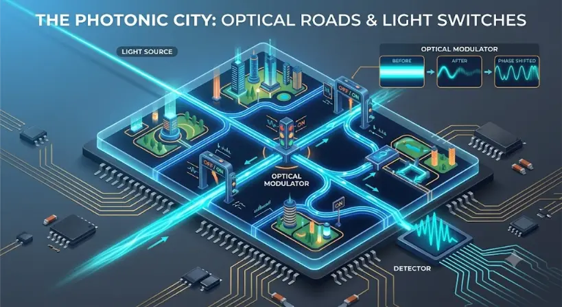
Photonic integrated circuits conceptualized as a miniature city grid. Optical waveguides function as roads to route data encoded in light, while built-in optical modulators act as traffic gates to change the properties of the signal before it reaches a final detector.
The image is a detailed 3D isometric scientific infographic comparing an integrated photonic chip to a miniature city layout. At the top left, a powerful blue laser beam labeled "Light Source" enters the main chip. The chip itself is a square platform divided into grid sectors featuring miniature futuristic buildings and parks. The beam splits and travels through a network of glowing, transparent channel pathways that represent optical waveguides acting as city streets. At a key intersection, a central pillar stylized like a traffic light is labeled "Optical Modulator," alongside archway gates labeled "OFF/ON." These gates signify modulation points that manipulate the beam. An inset diagram on the top right shows a step-by-step waveform transformation labeled "OPTICAL MODULATOR," depicting a constant stream ("Before") changing into a modulating wave ("After") and then a modified wavelength state ("Phase Shifted"). At the bottom right, the final structured light wave exits the city grid and hits a processing unit labeled "Detector," which translates the light into complex electronic signals traveling down copper-toned circuit paths.
The Evolutionary Path: History, Physical Confinement Hurdles, and Future Horizons
The structural evolution of routing light moved photonics past passive mirror layouts into active, self-contained data synthesis networks.
The Historical Journey
The foundation of optical guidance was demonstrated in 1870 when John Tyndall used a water jet to show that light could be trapped and steered along a curved path through total internal reflection. This macroscopic discovery scaled down to high-purity glass in 1966, when Charles Kao mathematically calculated the transmission benchmarks needed for low-loss fiber optics.
Control components evolved in parallel; by 1969, David Casasent and his team constructed the first solid-state spatial light modulators. Throughout the late 1980s, the development of high-index contrast silicon-on-insulator (SOI) fabrication techniques enabled engineers to construct integrated microcomb chip channels, transforming bulky benches into monolithic nanophotonic circuits.
Contemporary Technical Hurdles
The dominant boundary in designing nanoscale chip routes is the **optical diffraction limit**. Because a light wave leaks out of its path if the guiding cross-section is smaller than its operating wavelength, scaling down channel paths to match the sub-10nm dimensions of electronic transistors causes severe radiation losses and data crosstalk.
Additionally, high-speed electro-optic modulation requires high **drive voltages**, which generate localized thermal gradients. These temperature swings detune nearby sensitive microring resonator networks, requiring active, power-consuming thermal compensation arrays.
Future Horizons: Slot Waveguides and Topological Edge Propagation
Next-generation light routing bypasses conventional core boundaries by leveraging custom material geometries:
Sub-Diffraction Slot Waveguides: By sandwiching a low-index nanometer-scale air gap between two high-index silicon rails, engineers can trap electric fields directly outside the solid core. This technique forces light into sub-100nm slots, enhancing light-matter interaction for chemical sensing and low-power processing.
Topological Photonics and Defect-Immune Paths: Utilizing geometric honeycomb lattices inspired by quantum Hall effects, researchers are building waveguides that enforce unidirectional light travel. These topological edge tracks guide photons cleanly around sharp 90-degree corners and structural defects without generating any back-reflection or scatter losses.
Why Waveguides Are Needed
Light naturally spreads when it travels through open space. That spreading can be useful in some situations, but it is a problem when engineers need light to follow a compact, predictable path. A waveguide solves this problem by confining light so that it can travel through a fibre, a chip, or another optical structure.
The guiding effect usually depends on refractive index contrast. Light is kept mostly inside a core region because the surrounding material has a different refractive index. In many waveguides, the basic idea is related to total internal reflection, although chip-scale waveguides are often better described using optical modes and electromagnetic field confinement.
Waveguides allow photonic systems to become compact. Without waveguides, many optical systems would need large free-space arrangements of mirrors and lenses. With waveguides, light can be routed through small paths on a chip, much like electrons are routed through metal tracks in electronic circuits.
Total Internal Reflection and Light Confinement
A simple way to introduce waveguides is through total internal reflection. When light travels in a higher-index material and reaches the boundary with a lower-index material at a sufficiently large angle, it can be reflected back inside instead of passing out.
This idea helps explain optical fibres. A fibre has a core surrounded by cladding. If the core has a higher refractive index than the cladding, light can be guided along the fibre over long distances.
In chip-scale photonics, the same broad principle of confinement still matters, but the details can become richer. Light travels in guided modes, and the exact behaviour depends on waveguide width, height, refractive index, wavelength, polarisation, bending radius, and fabrication quality.
Types of Optical Waveguides
Waveguides can appear in several forms. The best waveguide depends on the application, the wavelength, the required size, the material platform, the acceptable loss, and the way light enters or leaves the structure.
Waveguide Type
Main Structure
Typical Use
Student-Friendly Picture
Optical fibre
Long glass or plastic core with cladding
Communication, sensing, medical imaging, laser delivery
A flexible light pipe
Slab waveguide
Thin guiding layer between surrounding materials
Basic waveguide theory and planar optics
A flat optical sheet
Channel waveguide
Narrow strip or ridge guiding light on a chip
Photonic integrated circuits and silicon photonics
An optical wire on a chip
Ridge waveguide
Raised guiding region shaped from a material layer
Integrated photonics, lasers, modulators, sensors
A raised road for light
Photonic crystal waveguide
Periodic structure that controls light propagation
Light inside a waveguide does not usually travel as a simple thin line. It forms guided patterns called modes. A mode describes how the electromagnetic field is distributed across the waveguide while the light travels forward.
Some waveguides support only one mode at a chosen wavelength. These are called single-mode waveguides. Others support multiple modes. Single-mode behaviour is often useful when a clean, predictable optical signal is needed, while multimode behaviour may be acceptable or useful in other contexts.
The idea of modes connects this page to Wave Optics. A waveguide does not merely “hold” light. It selects which wave patterns can travel through it.
Waveguide Losses
No real waveguide is perfect. As light travels, some optical power may be lost. Losses can come from absorption, scattering, imperfect surfaces, bending, material defects, poor coupling, or radiation out of the guide.
Loss Type
Cause
Why It Matters
Absorption loss
Material absorbs light energy
Reduces signal strength and may produce heat
Scattering loss
Surface roughness or defects redirect light
Important in small chip waveguides
Bending loss
Waveguide bends too tightly
Limits how compact a photonic circuit can be
Coupling loss
Light is not efficiently transferred into or out of the guide
Affects fibre-to-chip and chip-to-chip connections
Radiation loss
Light leaks out of the guided mode
Reduces efficiency and can cause unwanted crosstalk
Waveguide design is therefore a balance. Engineers want small devices, low loss, good confinement, low crosstalk, manageable fabrication, and easy coupling to sources or detectors.
Why Optical Modulators Are Needed
A steady beam of light is useful, but information systems need signals that change. To send data through light, some property of the optical wave must be varied in a controlled way. This process is called modulation.
A simple example is intensity modulation. The light can be made brighter or dimmer to represent information. More advanced systems may modulate phase, frequency, polarisation, or combinations of properties. In high-speed communication, optical modulation is one of the key steps that turns light into a data carrier.
Optical modulators also matter in sensing, computing, signal processing, and quantum technologies. They allow light to be switched, delayed, encoded, redirected, or controlled on demand.
Main Types of Optical Modulation
Different modulators change light in different ways. Students do not need to master every device at first. The important point is to understand what property of the light signal is being controlled.
Modulation Type
What Changes?
Simple Meaning
Typical Use
Intensity modulation
Brightness or optical power
Turn light up and down
Simple data transmission, sensors, optical links
Phase modulation
Phase of the optical wave
Shift the wave pattern
Coherent communication, interferometers, signal processing
Frequency modulation
Optical frequency
Slightly change the colour or frequency
Advanced communication, spectroscopy, measurement
Polarisation modulation
Electric-field orientation
Change the wave’s orientation
Optical systems, sensing, specialised communication
Pulse modulation
Timing and shape of pulses
Control when light appears
Digital links, lidar, timing systems
How Optical Modulators Work
An optical modulator works by changing how light experiences a material or device. This may be done using an electric field, heat, sound waves, carrier injection, carrier depletion, mechanical motion, or changes in refractive index.
Many modulators rely on the fact that the phase of light depends on the refractive index and the path length. If a device changes the refractive index experienced by the light, it can change the phase. If that phase change is converted into constructive or destructive interference, the device can control intensity.
This is why modulators often connect waveguides with interference structures. The waveguide directs the light; the modulator changes the condition through which the light travels.
Common Modulator Mechanisms
Mechanism
What Changes the Light?
Strength
Typical Limitation
Electro-optic modulation
Electric field changes refractive index
Can be fast and precise
Material choice and drive voltage matter
Thermo-optic modulation
Temperature changes refractive index
Simple and useful for tuning
Usually slower and may consume power
Carrier-based modulation
Electron or hole concentration changes optical properties
Useful in silicon photonics
Speed, loss, and efficiency trade-offs
Acousto-optic modulation
Sound waves create a moving optical grating
Useful for frequency shifting and beam control
Often larger than chip-scale devices
Electro-absorption modulation
Electric field changes absorption
Compact and useful in some semiconductor systems
May introduce optical loss and wavelength constraints
Mach-Zehnder Modulators
One of the most important modulator designs is based on the Mach-Zehnder interferometer. In a Mach-Zehnder modulator, light is split into two paths. One or both paths experience a controlled phase change. When the paths recombine, the waves interfere.
If the waves recombine in step, the output is strong. If they recombine out of step, the output is reduced. In this way, phase control can become intensity control.
This is a powerful idea for students because it connects modulation with interference. A modulator does not always need to block light directly. It can guide light through two paths and use wave interference to control the output.
Ring Resonator Modulators
Another important design is the ring resonator modulator. A ring resonator is a small circular or looped waveguide placed near a straight waveguide. At certain wavelengths, light can couple into the ring and circulate strongly.
If the resonance condition is changed, the amount of light transmitted through the nearby waveguide can change. This allows the device to modulate the optical signal. Ring resonators can be compact, which makes them attractive for photonic integrated circuits.
However, ring resonators also require careful wavelength and temperature control. Their strength is compactness; their challenge is sensitivity.
Waveguides and Modulators Working Together
In real photonic systems, waveguides and modulators are rarely isolated. A waveguide brings light into the modulator, guides it through the active region, and carries the modified signal onward. The modulator changes the signal while the waveguide provides the pathway.
This combination is central to photonic integrated circuits. On a chip, a laser or external fibre may bring in light. Waveguides route the light. Modulators encode data. Splitters divide signals. Filters select wavelengths. Detectors convert light back into electrical signals.
This is why students should see waveguides and modulators as paired ideas. One controls the path; the other controls the message.
Optical Modulators in Communication Systems
Optical communication requires information to be placed onto light. A modulator performs this task by changing the optical signal according to an electrical input. The modulated light can then travel through a fibre or waveguide to a detector.
In simple systems, the light may represent data by switching between high and low intensity. In more advanced systems, information may be encoded using phase, amplitude, polarisation, or combinations of signal properties. These methods allow higher data rates and more efficient use of optical channels.
On a photonic chip, waveguides guide light through tiny paths. These paths may bend, split, join, or pass through active devices. The challenge is to guide light without losing too much power or disturbing the signal.
Chip waveguides are important because they allow photonic systems to become smaller and more integrated. Instead of building an optical system from separate lenses, mirrors, fibres, and benches, many functions can be placed on a compact chip.
This idea prepares students for Photonic Integrated Circuits, where waveguides act as the connecting structure between many optical components.
Waveguides in Silicon Photonics
Silicon photonics uses semiconductor manufacturing ideas to build optical devices on silicon-based platforms. Waveguides are central to this field because they route light across the chip. Modulators are also central because they encode information onto optical signals.
Silicon itself does not behave like every ideal optical material. Engineers must work with its strengths and limits. Silicon can guide infrared light well in certain wavelength ranges, but creating efficient light sources directly in silicon is difficult. This is why silicon photonics often combines silicon waveguides with other materials, external lasers, germanium detectors, or hybrid integration approaches.
Case Studies: Modulators and Waveguides in Real Systems
Case Study 1: Fibre-Optic Internet
In a fibre-optic communication system, a laser provides light, a modulator encodes information, an optical fibre guides the signal over distance, and a photodetector receives the light at the far end. The system works because light can be both guided and controlled.
This case study shows the central role of waveguides and modulators. The fibre is the long-distance waveguide. The modulator writes the information. Without both, the system cannot function as a high-speed optical communication link.
Case Study 2: Data Centre Optical Interconnects
Inside modern data centres, huge amounts of information move between servers, processors, switches, and storage systems. Photonic links can help carry data at high speed over short or medium distances. Optical modulators help encode signals, while waveguides and fibres route those signals.
This case study shows why photonics matters for computing infrastructure. As electronic links face challenges in speed, heat, and bandwidth, optical links become increasingly important for moving information efficiently.
Case Study 3: Lab-on-Chip Optical Sensors
Some photonic sensors use waveguides to guide light through or near a sensing region. If a chemical, biological sample, gas, or liquid changes the optical environment, the guided light may change in phase, intensity, wavelength, or resonance condition.
A modulator or tunable element may help scan, adjust, or control the optical signal. This case study shows how waveguides can become sensing pathways, not just communication channels.
Case Study 4: Photonic Integrated Circuit Transmitters
A photonic integrated transmitter may include input light, waveguides, splitters, modulators, couplers, and output ports on one chip. The light may come from an external laser or an integrated source. The modulator encodes data, and the waveguides route the signal through the chip.
This case study shows the system-level importance of the topic. Optical modulators and waveguides are not secondary details. They are central parts of the architecture of modern photonic chips.
Connections with Wider Physics and Technology
Optical modulators and waveguides connect photonics with wave optics, fibre optics, electronics, computing, materials science, and semiconductor manufacturing. These related pages help students build a wider understanding.
Understand how guided and modulated light supports fibre networks, data centres, optical interconnects, and future computing systems.
Quick Check: Optical Modulators and Waveguides
Quick Check: Guiding and Controlling Light
Q1. What does an optical waveguide do?
An optical waveguide confines light and directs it along a chosen path, such as through an optical fibre or across a photonic chip.
Q2. What does an optical modulator do?
An optical modulator changes a property of light, such as intensity, phase, frequency, polarisation, or timing, so that information can be encoded or signals can be controlled.
Q3. Why are waveguides important in photonic chips?
Waveguides act like optical wiring on a chip. They route light between sources, modulators, filters, splitters, detectors, and other photonic components.
Q4. How can phase modulation become intensity modulation?
If light is split into two paths and one path has a controlled phase shift, the two waves can interfere when recombined. Constructive or destructive interference can change the output intensity.
Common Misunderstandings About Modulators and Waveguides
Misunderstanding 1: A Waveguide Is Just a Tiny Pipe for Light
A waveguide does guide light, but it is not simply an empty pipe. It confines electromagnetic waves through refractive index structure and supports particular optical modes. Its width, material, shape, and wavelength all affect how light travels.
Misunderstanding 2: Modulation Means Only Turning Light On and Off
Turning light on and off is one form of modulation, but optical signals can also be controlled through phase, frequency, polarisation, pulse timing, or combinations of several properties.
Misunderstanding 3: Smaller Photonic Devices Are Automatically Better
Smaller devices can be useful, but compactness may increase bending loss, fabrication sensitivity, thermal effects, or coupling difficulty. Good design balances size, loss, speed, power, reliability, and manufacturability.
Misunderstanding 4: Waveguides and Modulators Are Separate Topics
In real photonic systems, waveguides and modulators work together. The waveguide delivers the optical field to the modulator, and the modulator changes the signal while it travels through or near the guided path.
Key Terms
Coupling
The transfer of light from one optical component into another, such as from a fibre into a chip waveguide.
Electro-optic effect
A change in optical properties caused by an electric field.
Guided mode
An allowed electromagnetic field pattern that can travel along a waveguide.
Insertion loss
Loss of optical power caused by adding a component or connection to an optical path.
Intensity modulation
Changing the brightness or optical power of a signal.
Mach-Zehnder modulator
A modulator that splits light into two paths, changes phase in one or both paths, and recombines the light to control output intensity.
Multimode waveguide
A waveguide that supports more than one guided mode.
Optical modulator
A device that changes a property of light, such as intensity, phase, frequency, polarisation, or timing.
Optical waveguide
A structure that confines and guides light along a chosen path.
Phase modulation
Changing the phase of an optical wave to encode or control a signal.
Refractive index contrast
The difference in refractive index between the guiding region and surrounding material.
Ring resonator
A looped waveguide structure that strongly interacts with light at resonant wavelengths.
Single-mode waveguide
A waveguide that supports only one main guided mode at a chosen wavelength.
Thermo-optic effect
A change in refractive index caused by temperature.
Total internal reflection
A condition in which light reflects back inside a material instead of escaping across a boundary.
Review Questions
What is the main function of an optical waveguide?
Answer: An optical waveguide confines and directs light along a chosen path, such as through an optical fibre or across a photonic chip.
What is the main function of an optical modulator?
Answer: An optical modulator changes a property of light, such as intensity, phase, frequency, polarisation, or timing, to encode information or control an optical signal.
Why is refractive index contrast important in waveguides?
Answer: Refractive index contrast helps confine light to the guiding region. It affects mode behaviour, confinement strength, bending loss, and waveguide design.
What is a guided mode?
Answer: A guided mode is an allowed field pattern that can travel along a waveguide without quickly radiating away.
How does a Mach-Zehnder modulator control light intensity?
Answer: It splits light into two paths, changes the phase in one or both paths, and recombines the light. The resulting interference can increase or reduce the output intensity.
Why are waveguides important for photonic integrated circuits?
Answer: Waveguides connect different optical components on a chip, allowing light to move between sources, modulators, filters, splitters, and detectors.
Thought-Provoking Questions
Why might guiding light on a chip be compared with wiring electrons on an electronic circuit board?
Answer: Both provide controlled pathways for signals. Electronic wires guide electrical currents, while optical waveguides guide light. In both cases, the path structure shapes how information moves through a system.
Why is optical modulation central to communication?
Answer: Communication requires a signal to carry information. Optical modulation allows information to be placed onto light by changing properties such as intensity, phase, timing, or polarisation.
Why does miniaturising photonic devices create both opportunities and challenges?
Answer: Miniaturisation allows compact circuits, lower footprint, and integration with electronics. However, it can also increase sensitivity to fabrication errors, bending losses, heat effects, and coupling challenges.
How do modulators and waveguides show the connection between physics and information technology?
Answer: Physics explains wave propagation, phase, interference, refractive index, and optical confinement. Information technology uses those effects to encode, route, and process data as light signals.
Comprehensive Numerical Problems with Solutions
Light travels in a waveguide with an effective refractive index n = 1.50. Estimate the speed of light in the waveguide using the standard phase velocity relationship.
Solution:
Using the structural phase velocity index equation:
$$v = \frac{c}{n}$$
Substitute the constants ($c = 3.00 \times 10^8\text{ m/s}$ and $n = 1.50$):
Answer: The signal transit interval equals exactly 10 ns.
A waveguide channel entrance receives 5.0 mW of optical laser power. If the exiting terminal registers exactly 3.0 mW, evaluate what percentage fraction of the original input power remains.
Solution:
Calculate the ratio of throughput power over entry power:
Convert the ratio parameter into a percentage value:
$$\text{Percentage} = 0.60 \times 100\% = 60\%$$
Answer: Exactly 60% of the initial optical power is retained.
A simple electro-absorption intensity modulator switches its throughput optical power from 8.0 mW in the baseline “on” state down to 2.0 mW during the biased “low” state. Find the net operational power delta difference.
Solution:
Subtract the localized low-state power parameter from the peak power constant:
Answer: The net modulated power difference is exactly 6.0 mW.
A coherent optical telecom link transmits 1.0 × 10⁹ modulated wave symbols per second. If advanced phase coding maps exactly 2 bits into each distinct symbol unit, estimate the net bit rate capacity.
Solution:
The aggregate digital bit rate represents the product of symbol frequency and bit density:
$$\text{Bit Rate} = \text{Symbol Rate} \times \text{Bits per Symbol}$$
Optical modulators and waveguides matter because they turn light from a beam into a controllable information system. A light source alone is not enough. The light must be guided to the right place, changed in the right way, and delivered to the right detector or device.
For students, this topic connects physics with real technology. Refractive index, interference, phase, guided modes, and total internal reflection are not only textbook ideas. They shape fibre networks, data centres, optical sensors, photonic chips, silicon photonics, and future computing systems.
The deeper lesson is that photonics is not just about producing light. It is about giving light a path, a message, and a purpose.
Summary
An optical waveguide confines and directs light along a chosen path. It may be an optical fibre, a slab waveguide, a channel waveguide, a ridge waveguide, or a more advanced guiding structure. Waveguides make compact and integrated photonic systems possible.
An optical modulator changes a property of light, such as intensity, phase, frequency, polarisation, or timing. Modulators allow information to be encoded onto optical signals and allow photonic systems to switch, tune, route, and process light.
Together, waveguides and modulators form the routing and control system of photonics. They prepare students for photonic integrated circuits, silicon photonics, optical communication, and light-based computing.
Reflection Question
If waveguides give light a path and modulators give light a message, how might future technologies use controlled light differently from today’s electronic circuits?