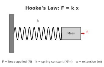
🔢 2. Hooke’s Law and Elastic Forces
Hooke’s law (linear elasticity)
- Magnitude form: \( F = k\,x \), where
\(F\) is the applied/restoring force (N), \(k\) the spring constant (N·m\(^{-1}\)), and \(x\) the extension or compression (m). - Vector/sign-convention form: the spring’s restoring force opposes the displacement:
\( \vec{F}_{\text{spring}} = -\,k\,\vec{x} \). - Elastic potential energy stored in the spring:
\( U(x)=\frac12\,k\,x^{2} \) (J).
Static equilibrium with weight: If a mass \(m\) hangs from a vertical spring and comes to rest after stretching by \(x\),
then \( \sum F_y=0 \Rightarrow kx = mg \Rightarrow x=\frac{mg}{k} \).
Series/parallel springs (effective stiffness)
- Series: \( \displaystyle \frac{1}{k_{\mathrm{eq}}}=\frac{1}{k_1}+\frac{1}{k_2}\;\Rightarrow\;
k_{\mathrm{eq}}=\frac{k_1 k_2}{k_1+k_2} \). - Parallel: \( k_{\mathrm{eq}}=k_1+k_2 \).
Graph method (lab tip): Plot applied force \(F\) (y-axis) vs extension \(x\) (x-axis). The best-fit straight line
has slope \(k\) (units N·m\(^{-1}\)). The linear region ends near the elastic limit.
Worked example
A spring stretches \(4~\text{cm}=0.04~\text{m}\) under a \(2~\text{N}\) load. Find \(k\).
Using \( F=kx \Rightarrow k=\frac{F}{x}=\frac{2}{0.04}= \mathbf{50}~\text{N·m}^{-1}. \)
📐 Learning-Check 1
A spring extends \(0.08~\text{m}\) when a \(4~\text{N}\) force is applied. What is \(k\)?
Solution:
\( k=\frac{F}{x}=\frac{4}{0.08}= \mathbf{50}~\text{N·m}^{-1}. \)
📐 Learning-Check 2
True or False: Hooke’s law holds for any deformation, even if the spring is permanently stretched.
Answer: False.
Hooke’s law applies only within the elastic limit. Beyond yield, the \(F\)–\(x\) relation is no longer linear and permanent deformation can occur.
Common pitfalls: (i) forgetting to convert cm to m; (ii) using \(F= kx\) with the wrong sign when writing vector equilibrium;
(iii) assuming linear behavior beyond the elastic limit; (iv) mixing weight \(W=mg\) with mass \(m\) (units!).
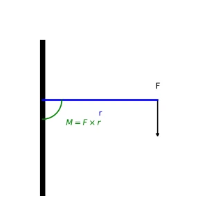
🔢3. Moment and Torque
What is a moment? The moment of a force (turning effect) about a pivot measures how strongly the force tends to rotate an object.- Scalar (perpendicular) definition: For a force applied perpendicularly at a distance r from the pivot, \( \;M = F\,r\; \) with SI unit N·m.
- General (angled) case: When the force makes an angle \( \theta \) to the lever arm, \[ M = F\,r\,\sin\theta \quad\text{or}\quad M = F_\perp\,r, \] where \( F_\perp = F\sin\theta \) is the component of the force perpendicular to the lever arm.
- Vector definition (torque): \( \vec{\tau} = \vec{r} \times \vec{F} \); \( \|\vec{\tau}\| = r\,F\,\sin\theta \). Direction given by the right-hand rule (thumb = \( \vec{\tau} \), fingers curl from \( \vec{r} \) to \( \vec{F} \)).
- Units: Newton–metre (N·m). Moments/torques are not “joules” even though \(1~\text{N·m} = 1~\text{J}\) dimensionally; energy is a scalar work quantity, torque is an axial (pseudovector) quantity.
- Sign convention: In 2D statics, take counter-clockwise positive (CCW \(+\)), clockwise negative (CW \(−\)). Be consistent across the page.
📐 Learning-Check 1 (moment magnitude): A \(12~\text{N}\) force is applied at a perpendicular distance \(0.25~\text{m}\) from a pivot. Compute \(M\). \[ M = F\,r = 12 \times 0.25 = \mathbf{3.0}~\text{N·m}. \]
📐 Learning-Check 2 (lever arm from torque): A spanner applies a torque of \(10~\text{N·m}\). If the applied force is \(20~\text{N}\), find the perpendicular distance \(d\). \[ \tau = F\,d \;\Rightarrow\; d = \frac{\tau}{F} = \frac{10}{20} = \mathbf{0.50}~\text{m}. \]
SEO note for learners: Engineers often search “moment vs torque,” “lever arm,” and “right-hand rule.” Remember: moment is the turning effect; torque is the vector form \( \boldsymbol{\tau} = \boldsymbol{r} \times \boldsymbol{F} \); use \(M = F\,r\,\sin\theta\) for angled forces, and N·m as the SI unit.🔢4. Couples and the Principle of Moments
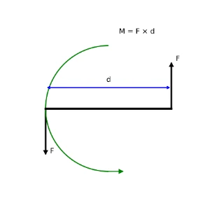
Couple:- Two equal and opposite forces acting on different lines.
- Produces pure rotation (no net force, only turning effect).
- For an object in rotational equilibrium: Sum of clockwise moments = Sum of anticlockwise moments
- The picture below illustrates the moment due to two equal forces F acting at distance D apart but in opposite directions, forming a rotating moment called a pure couple.
📐Learning-Check 1: Two equal and opposite forces of 15 N act on a steering wheel, 0.4 m apart. What is the moment (torque) produced by this couple?
Solution: Moment of a couple = One force × Distance between forces = 15 N × 0.4 m = 6 Nm
📐Learning-Check 2: A plank is balanced on a pivot. A 30 N weight is placed 1.2 m from the pivot. What weight must be placed 0.8 m on the other side to balance the plank?
Solution: Clockwise moment = 30 N × 1.2 m = 36 Nm To balance: Anticlockwise moment = W × 0.8 m → W = 36 / 0.8 = 45 N
🔢5. Equilibrium Conditions
Translational Equilibrium (no net force):
- Object remains at rest or moves with constant velocity (Newton’s First Law).
- In 2D:
\( \sum F_x = 0,\quad \sum F_y = 0. \) - In 3D, also \( \sum F_z = 0 \).
Rotational Equilibrium (no net moment/torque):
- No angular acceleration; object does not start/stop spinning.
- About any chosen pivot:
\( \sum M = 0. \)
Free-Body Diagrams (FBDs):
- Show the body as a simple shape (point/box/beam) and draw all external forces acting on it (no internal forces between parts of the same rigid body).
- Label magnitudes and directions; choose and mark a sign convention for moments (e.g., counter-clockwise \(+\)).

- Friction models (useful in FBDs):
- Static friction (no slip): \( |f| \le \mu_s N \) (at impending motion: \( f=\mu_s N \)).
- Kinetic friction (sliding): \( f_k = \mu_k N \) opposing motion.
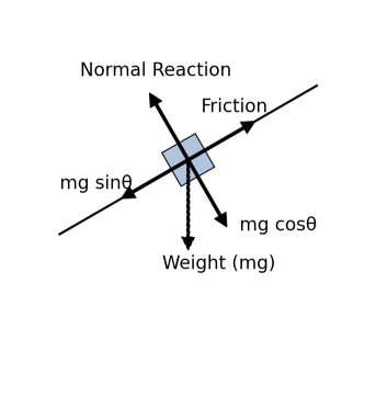
Inclined Plane Decomposition (angle \( \theta \) to horizontal):
- Weight: \( mg \) acts vertically downward.
- Components along/normal to plane:
\( \;mg\sin\theta \) (down the plane), \( mg\cos\theta \) (into the plane). - Normal reaction (no lift-off): \( N = mg\cos\theta \) (if no other vertical forces).
- If at rest (no slip): \( \sum F_{\parallel}=0 \Rightarrow f = mg\sin\theta \) with \( |f|\le \mu_s N \).
Beam Equilibrium (supports & moments):
A beam is in equilibrium when both translation and rotation balance:
\( \sum F_x=0,\; \sum F_y=0,\; \sum M=0 \).
For a simply supported beam with reactions \(R_A, R_B\), and a point load \(P\) at distance \(a\) from support \(A\):
Choose moments about \(A\):
\( \sum M_A = 0 \Rightarrow R_B L – P a = 0 \Rightarrow R_B = \frac{P a}{L}. \)
Then vertical forces:
\( \sum F_y = 0 \Rightarrow R_A + R_B – P = 0 \Rightarrow R_A = P – \frac{P a}{L} = P\!\left(1-\frac{a}{L}\right). \)

Worked Example (Ladder idea, FBD thinking)
A ladder leans against a rough wall and rests on a rough floor. Draw the FBD: weight \(mg\) at the ladder’s centre, normal reactions at wall and floor, and friction forces at both contacts opposing possible slip. Apply
\( \sum F_x=0,\; \sum F_y=0,\; \sum M=0 \)
about a convenient pivot (often the floor contact) to find unknown reactions. Check that any friction forces obey \( |f|\le \mu N \).
📐Learning-Check 1:
Draw an FBD for a box pushed across a rough floor at constant speed. Label all forces and write the equilibrium equations.
Answer (sketch & equations):
Forces: applied \(F\) (forward), friction \(f_k\) (back), weight \(mg\) (down), normal \(N\) (up). Since speed is constant:
\( \sum F_x=0 \Rightarrow F – f_k=0,\;
\sum F_y=0 \Rightarrow N – mg = 0,\;
f_k=\mu_k N. \)
📐Learning-Check 2:
A beam is in static equilibrium. Which must be true?
A) \( \sum F \ne 0 \) and \( \sum M = 0 \)
B) \( \sum F = 0 \) and \( \sum M = 0 \)
C) \( \sum F = 0 \) and \( \sum M \ne 0 \)
D) \( \sum F \ne 0 \) and \( \sum M \ne 0 \)
Answer: B) \( \sum F = 0 \) and \( \sum M = 0 \).
Explanation: Complete (static) equilibrium requires zero net force and zero net moment.
- \(A = 80~\text{N}\) directed horizontally to the right,
- \(B = 60~\text{N}\) directed vertically upward.
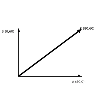
Section 1 — Graphical (tip-to-tail) vector addition
- From O, draw vector \( \vec A \) to the right (length ∝ 80 N).
- From the tip of \( \vec A \), draw vector \( \vec B \) upward (length ∝ 60 N).
- The closing vector from the tip of \( \vec B \) back to O is the reaction \( \vec R \), satisfying \( \vec A + \vec B + \vec R = \vec 0 \Rightarrow \vec R = -(\vec A + \vec B)\).
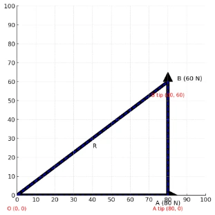
Vector addition (tip-to-tail): the reaction is equal in magnitude and opposite in direction to the resultant.
Section 2 — Resolved-component (analytic) method
- Resolve forces into Cartesian components (take \(+x\) to the right, \(+y\) upward): \[ \vec A = (80,\,0)\ \text{N},\qquad \vec B = (0,\,60)\ \text{N}. \]
- Resultant that must be opposed: \[ \vec A + \vec B = (80,\,60)\ \text{N} \quad\Rightarrow\quad \vec R = -(\vec A+\vec B) = (-80,\,-60)\ \text{N}. \]
- Magnitude of the reaction: \[ |\vec R| = \sqrt{(-80)^{2}+(-60)^{2}} = \sqrt{6400+3600} = \sqrt{10000} = 100~\text{N}. \]
- Direction of the reaction (angle from the \(+x\) axis): \[ \theta_R = \tan^{-1}\!\left(\frac{R_y}{R_x}\right) = \tan^{-1}\!\left(\frac{-60}{-80}\right). \] Since \(R_x<0\) and \(R_y<0\), \(\vec R\) lies in the third quadrant, so add \(180^\circ\): \[ \theta_R = 180^\circ + \tan^{-1}\!\left(\frac{60}{80}\right) \approx 180^\circ + 36.87^\circ = 216.87^\circ. \] (Equivalently: \(36.87^\circ\) below the \(-x\) direction.)
Component method: sum components, then use \( |\vec R|=\sqrt{R_x^2+R_y^2} \) and \( \theta_R=\tan^{-1}(R_y/R_x) \) with the correct quadrant.
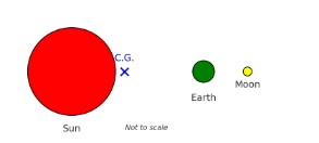
Example 2: Centre of Gravity (Barycentre) of the Sun–Earth–Moon System
Problem. Three bodies lie (approximately) on a line:
- Sun: mass \(M_{\odot}=1.989\times 10^{30}\,\text{kg}\) at \(x_{\odot}=0\).
- Earth: mass \(M_E=5.972\times 10^{24}\,\text{kg}\) at \(x_E=1\,\text{AU}=1.496\times 10^{11}\,\text{m}\).
- Moon: mass \(M_m=7.347\times 10^{22}\,\text{kg}\) at \(x_m=1.496\times 10^{11}+3.84\times 10^{8}=1.49984\times 10^{11}\,\text{m}\).
Method (1D barycentre): The centre of gravity along this line is
\[ x_{\text{CG}}=\frac{\sum_i M_i x_i}{\sum_i M_i}. \]
- Total mass.
\[ M_{\text{tot}}=M_{\odot}+M_E+M_m =1.989006045\times 10^{30}\,\text{kg}\quad(\text{to }7\ \text{sig. figs.}) \]
- Weighted sum of positions.
\[ \sum_i M_i x_i =M_{\odot}x_{\odot}+M_E x_E+M_m x_m =0+(5.972\times 10^{24})(1.496\times 10^{11}) +(7.347\times 10^{22})(1.49984\times 10^{11}). \] \[ \sum_i M_i x_i \approx 9.044305245\times 10^{35}\ \text{kg·m}. \]
- Centre of gravity.
\[ x_{\text{CG}} =\frac{9.044305245\times 10^{35}}{1.989006045\times 10^{30}} \ \text{m} \approx 4.547\times 10^{5}\ \text{m}. \]
Answer. \(\displaystyle x_{\text{CG}}\approx 4.55\times 10^{5}\ \text{m}\) from the Sun’s centre (about \(4.55\times 10^{5}\,\text{m} = 455\,\text{km}\) along the Sun–Earth line). This lies deep inside the Sun (solar radius \(\sim 6.96\times 10^{8}\,\text{m}\)).
Notes for students (accuracy & modelling):
- This is a collinear approximation. In reality the bodies move in 3D; the true instantaneous barycentre is still given by the same mass-weighted sum in vector form.
- The Sun’s dominance (\(M_{\odot}\gg M_E\gg M_m\)) keeps the barycentre well inside the Sun; adding the Moon shifts it only slightly from the Sun–Earth two-body value.
- For vectors in 3D, replace \(x_i\) with \(\vec r_i\): \(\displaystyle \vec r_{\text{CG}}=\frac{\sum_i M_i \vec r_i}{\sum_i M_i}\).
Also called: barycentre, mass centre of a multi-body system. Key idea: mass-weighted average of positions.
Example 3: Maximum Incline Before Sliding
Problem. A box of mass \(m=10~\text{kg}\) rests on a rough plane. The coefficient of static friction is \(\mu=0.20\). What is the largest angle \(\theta_{\max}\) (measured from the horizontal) for which the box does not start sliding?
- Resolve forces.
Take the plane angle as \(\theta\) to the horizontal. Then the weight components relative to the plane are: \[ W_{\parallel}=mg\sin\theta,\qquad W_{\perp}=mg\cos\theta, \] and the normal reaction is \[ N=W_{\perp}=mg\cos\theta. \] At impending motion (just about to slip up or down the plane), the maximum static friction is \[ f_{\max}=\mu N=\mu\,mg\cos\theta. \]
- Limiting equilibrium at the threshold of sliding.
For a box on the verge of sliding down, friction acts up the plane with magnitude \(f_{\max}\). Balance along the plane: \[ \underbrace{mg\sin\theta}_{\text{down-plane}}=\underbrace{f_{\max}}_{\text{up-plane}}=\mu\,mg\cos\theta. \]
- Solve for \(\theta_{\max}\).
Cancel \(mg>0\) and divide by \(\cos\theta\): \[ \tan\theta_{\max}=\mu \quad\Longrightarrow\quad \theta_{\max}=\arctan(\mu)=\arctan(0.20)\approx 11.31^{\circ}. \]
Answer. \(\displaystyle \theta_{\max}\approx 11.3^{\circ}\).
Why mass cancels. The result depends only on the friction coefficient and the plane angle because both driving (\(mg\sin\theta\)) and resisting (\(\mu mg\cos\theta\)) terms are proportional to \(m\).
Static vs kinetic friction. This \(\theta_{\max}\) uses static friction \(\mu\). Once sliding begins, the coefficient drops to the kinetic value \(\mu_k\) (typically \(\mu_k<\mu\)), so the required angle to keep sliding can be smaller.
Direction check. For an up-slope impending motion (you push uphill), the balance becomes \(mg\sin\theta+\text{(applied up-slope shortfall)}=\mu mg\cos\theta\); the limiting angle relation \(\tan\theta_{\max}=\mu\) still marks the onset of unavoidable down-slope slip when no extra force is applied.