
The Otto Cycle is the ideal thermodynamic cycle used to understand spark-ignition petrol engines. It models how a fuel-air mixture is compressed, heated rapidly, expanded to produce work, and then returned to its starting condition by rejecting heat. Although real petrol engines are more complex, the Otto Cycle gives students a clean first model for understanding engine efficiency, compression ratio, and heat-to-work conversion.
This page belongs to the Thermodynamic Cycles cluster within Thermodynamics. It follows the Carnot Cycle, which sets the ideal efficiency limit, and prepares students to compare engine cycles such as the Diesel Cycle, Rankine Cycle, Brayton Cycle, and Refrigeration and Heat Pump Cycles.
The central idea of the Otto Cycle is that useful work can be produced by compressing a gas, adding heat rapidly at nearly constant volume, allowing the hot high-pressure gas to expand, and then rejecting heat. In real petrol engines, combustion replaces ideal heat addition, exhaust replaces ideal heat rejection, and mechanical parts introduce losses. Even so, the Otto Cycle remains one of the most important first models in automotive engineering and Thermodynamics and Heat Transfer.
Students should not think of the Otto Cycle as a perfect picture of a real engine. It is a simplified map. Like all useful maps, it leaves out some details so that the main structure becomes easier to see.
Interactive Otto Cycle Calculator & Simulator
Explore how the compression ratio (r), initial temperature (T1), and specific heat ratio (γ) impact the ideal thermal efficiency, peak pressure, peak temperature, and cycle states. Adjust the parameters below to dynamically re-calculate state variables and update the visual P–V diagram.
THERMAL EFFICIENCY (η)
56.5%
PEAK TEMP (T3)
1804 K
COMP. TEMP (T2)
689 K
NET WORK (Wnet)
452 kJ/kg
What the Otto Cycle Really Is
The Otto Cycle is an ideal air-standard cycle. In the simplest model, the working fluid is treated as air, combustion is replaced by heat addition, exhaust is replaced by heat rejection, and all processes are assumed internally reversible.
The cycle is most closely associated with spark-ignition petrol engines, where a fuel-air mixture is compressed and then ignited by a spark plug. The actual combustion process in a real engine is fast, complex, chemically reactive, and not perfectly constant-volume. The ideal Otto Cycle replaces that real combustion event with a simpler constant-volume heat-addition process.
| Feature | Otto Cycle Meaning | Real Engine Connection |
|---|---|---|
| Air-standard model | Working fluid is idealised as air | Real engines use a fuel-air mixture and combustion products |
| Constant-volume heat addition | Heat is added while volume is fixed | Approximates rapid combustion near top dead centre |
| Isentropic compression and expansion | Compression and expansion are ideal and reversible | Real engines have friction, heat loss, turbulence, and leakage |
| Compression ratio | Key design variable controlling ideal efficiency | Higher compression ratio usually improves efficiency but may cause knocking |
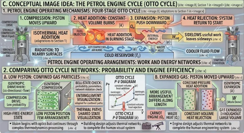
Detailed conceptual infographic of the four-stroke petrol engine (Otto Cycle). The upper panel charts the physical mechanical cycle from compression to exhaust reset, while the lower panel bridges these steps to statistical mechanics alongside a classic thermodynamic P–V diagram.
The Four Ideal Processes of the Otto Cycle
The ideal Otto Cycle consists of four internally reversible processes. Two are isentropic processes, and two occur at constant volume.
| Stage | Process | Main Event | Heat or Work Meaning |
|---|---|---|---|
| 1 → 2 | Isentropic compression | Air is compressed from large volume to small volume | Work is done on the gas; temperature and pressure rise |
| 2 → 3 | Constant-volume heat addition | Heat is added rapidly while volume remains fixed | Pressure and temperature rise sharply |
| 3 → 4 | Isentropic expansion | Hot gas expands and pushes the piston outward | Gas does work; pressure and temperature fall |
| 4 → 1 | Constant-volume heat rejection | Heat is rejected while volume remains fixed | Pressure and temperature return toward the initial state |
Process 1 → 2: Isentropic Compression
The gas is compressed without heat transfer and without internal irreversibility. In the ideal model, this process is isentropic, meaning entropy remains constant.
During compression, work is done on the gas. Its volume decreases, while its pressure and temperature increase. This prepares the gas for heat addition at a much higher temperature and pressure.
For an ideal gas with constant specific heats:
T2 / T1 = rγ − 1
P2 / P1 = rγ
Here, r is the compression ratio and γ is the ratio of specific heats.
Process 2 → 3: Constant-Volume Heat Addition
Heat is added while the volume remains constant. In a real spark-ignition engine, this corresponds roughly to the rapid burning of the fuel-air mixture near top dead centre.
Since volume is constant, boundary work during this ideal step is zero. The added heat raises the internal energy of the gas, increasing its temperature and pressure.
For the ideal air-standard Otto Cycle:
Qin = m cv (T3 − T2)
Process 3 → 4: Isentropic Expansion
The hot high-pressure gas expands, pushing the piston and producing work. This is the power-producing part of the cycle.
In the ideal model, there is no heat transfer and no entropy generation during expansion. Temperature and pressure fall as the gas does work.
For an ideal gas with constant specific heats:
T3 / T4 = rγ − 1
P3 / P4 = rγ
Process 4 → 1: Constant-Volume Heat Rejection
Heat is rejected while volume remains constant, returning the working fluid toward its initial state in the ideal cycle.
For the ideal air-standard Otto Cycle:
Qout = m cv (T4 − T1)
In a real engine, this ideal heat-rejection step is not an exact physical event. Real engines expel exhaust gases and draw in a fresh mixture. The air-standard cycle simplifies these processes so that the main energy conversion pattern can be studied clearly.
The Otto Cycle on a Pressure-Volume Diagram
On a pressure-volume diagram, the Otto Cycle appears as a closed loop. The area inside the loop represents the net work output per cycle.
| Process | Appearance on P–V Diagram | Meaning |
|---|---|---|
| 1 → 2 | Curved compression path | Volume decreases while pressure rises |
| 2 → 3 | Vertical line upward | Heat is added at constant volume; pressure rises sharply |
| 3 → 4 | Curved expansion path | Gas expands and produces work |
| 4 → 1 | Vertical line downward | Heat is rejected at constant volume; pressure falls |
The expansion curve produces more work than the compression curve requires, so the cycle produces a positive net work output. A larger enclosed area on the P–V diagram means more net work per cycle.
The Otto Cycle on a Temperature-Entropy Diagram
On a temperature-entropy diagram, the isentropic compression and expansion processes are vertical lines because entropy remains constant. Heat addition and heat rejection occur at constant volume and involve changes in entropy.
| Process | Path on T–S Diagram | Thermal Meaning |
|---|---|---|
| 1 → 2 | Vertical upward path | Isentropic compression raises temperature |
| 2 → 3 | Heat-addition path to higher entropy and temperature | Thermal energy is added to the gas |
| 3 → 4 | Vertical downward path | Isentropic expansion lowers temperature |
| 4 → 1 | Heat-rejection path to lower entropy and temperature | Thermal energy is rejected |
The T–S diagram helps students see heat transfer more directly because, for internally reversible processes, heat transfer is related to temperature and entropy change.
Compression Ratio
The compression ratio is one of the most important quantities in the Otto Cycle. It is defined as the ratio of maximum cylinder volume to minimum cylinder volume:
r = V1 / V2
Here, V1 is the volume before compression, and V2 is the volume after compression. In piston-engine language, V1 corresponds to the larger volume near bottom dead centre, while V2 corresponds to the smaller volume near top dead centre.
| Compression Ratio Effect | Ideal Otto Cycle Result | Real Engine Concern |
|---|---|---|
| Higher r | Higher ideal thermal efficiency | Greater risk of knocking and higher mechanical stress |
| Lower r | Lower ideal thermal efficiency | May be safer for poor fuel quality but less efficient |
| Very high r | Attractive in theory | Limited by fuel, materials, combustion timing, and engine design |
Thermal Efficiency of the Otto Cycle
The thermal efficiency of a heat-engine cycle is the fraction of heat input converted into net work:
η = Wnet / Qin
Since the net work is the difference between heat input and heat rejected:
Wnet = Qin − Qout
the efficiency becomes:
η = 1 − (Qout / Qin)
For the ideal air-standard Otto Cycle with constant specific heats:
ηOtto = 1 − (1 / rγ − 1)
This equation reveals the main ideal lesson of the Otto Cycle: increasing compression ratio increases ideal thermal efficiency.
| Symbol | Meaning | Typical Role |
|---|---|---|
| ηOtto | Ideal Otto Cycle thermal efficiency | Measures fraction of heat input converted into net work |
| r | Compression ratio | Main design variable in ideal efficiency |
| γ | Ratio of specific heats, cp/cv | Depends on working gas properties |
| Qin | Heat added during constant-volume process | Ideal replacement for combustion energy input |
| Qout | Heat rejected during constant-volume process | Ideal replacement for exhaust and cooling losses |
Why Higher Compression Ratio Improves Ideal Efficiency
A higher compression ratio raises the temperature of the gas before heat addition. This allows the cycle to operate over a wider temperature range and extract more useful work from the same heat input in the ideal model.
However, real engines cannot increase compression ratio without limit. If the fuel-air mixture auto-ignites before the spark-controlled flame front arrives, engine knocking can occur. Knocking can reduce efficiency, increase noise, and damage engine components.
| Ideal Advantage | Real Limitation | Engineering Response |
|---|---|---|
| Higher efficiency with larger r | Knocking risk increases | Use suitable fuel octane rating and combustion control |
| Higher pressure and temperature after compression | Greater thermal and mechanical stress | Improve materials, cooling, and engine structure |
| More useful expansion work | More demanding timing and heat-loss control | Optimise ignition timing, valve timing, and chamber shape |
Air-Standard Assumptions
The Otto Cycle is often studied using air-standard assumptions. These assumptions make the mathematics manageable, but they also remind students that the model is not a full real-engine simulation.
| Air-Standard Assumption | Simplification | What Real Engines Do Instead |
|---|---|---|
| Working fluid is air | Air circulates in a closed loop | Real engines use fuel-air mixture, combustion products, intake, and exhaust |
| Combustion is heat addition | Energy is added at constant volume | Real combustion is chemical, time-dependent, and spatially complex |
| Exhaust is heat rejection | Heat is rejected at constant volume | Real engines expel hot gases and admit fresh charge |
| Compression and expansion are isentropic | No friction, leakage, turbulence, or heat loss | Real engines have irreversibilities and heat transfer |
| Specific heats are often constant | cp, cv, and γ are fixed | Specific heats vary with temperature |
Otto Cycle and the Four-Stroke Petrol Engine
The ideal Otto Cycle is related to the four-stroke petrol engine, but it is not identical to the mechanical four-stroke sequence. The real engine has intake, compression, power, and exhaust strokes. The ideal cycle focuses on thermodynamic state changes.
| Real Four-Stroke Engine Event | Thermodynamic Meaning | Connection with Otto Cycle |
|---|---|---|
| Intake stroke | Fresh fuel-air mixture enters cylinder | Not represented directly in the closed ideal Otto Cycle |
| Compression stroke | Mixture is compressed | Approximated by isentropic compression, 1 → 2 |
| Spark and combustion | Chemical energy is released rapidly | Approximated by constant-volume heat addition, 2 → 3 |
| Power stroke | Hot gases expand and push piston | Approximated by isentropic expansion, 3 → 4 |
| Exhaust stroke | Combustion products leave cylinder | Idealised as heat rejection and cycle reset, 4 → 1 |
This comparison helps students avoid a common confusion: the Otto Cycle is a thermodynamic idealisation, while the four-stroke engine is a mechanical operating sequence.
Mean Effective Pressure
Mean effective pressure is a useful way to describe how much work a piston engine produces relative to its displacement volume. It is not the actual cylinder pressure at every instant. Instead, it is an average pressure that would produce the same net work if it acted on the piston through the displacement volume.
A common definition is:
MEP = Wnet / (V1 − V2)
Here, Wnet is the net work per cycle, and V1 − V2 is the displacement volume in the ideal model.
| Quantity | Meaning | Why It Matters |
|---|---|---|
| MEP | Equivalent average pressure producing the net work | Useful for comparing engine performance |
| Wnet | Net work output per cycle | Related to power output |
| V1 − V2 | Displacement volume | Represents piston swept volume in the ideal cycle |
Otto Cycle Versus Carnot Cycle
The Carnot Cycle gives the maximum possible efficiency between two temperature reservoirs. The Otto Cycle gives a more practical idealisation of a spark-ignition engine. The two cycles answer different questions.
| Feature | Carnot Cycle | Otto Cycle |
|---|---|---|
| Main purpose | Defines maximum possible efficiency | Models spark-ignition engine behaviour |
| Heat addition | Isothermal | Constant volume |
| Heat rejection | Isothermal | Constant volume |
| Main efficiency variable | Hot and cold reservoir temperatures | Compression ratio and γ |
| Practical relevance | Theoretical benchmark | Petrol engine idealisation |
| Real-engine closeness | Very ideal and not engine-specific | Closer to spark-ignition engine analysis |
Otto Cycle Versus Diesel Cycle
The Otto Cycle and Diesel Cycle are both ideal air-standard engine cycles, but they differ mainly in how heat is added.
| Feature | Otto Cycle | Diesel Cycle |
|---|---|---|
| Typical engine association | Spark-ignition petrol engine | Compression-ignition diesel engine |
| Ideal heat addition | Constant volume | Constant pressure |
| Ignition method in real engine | Spark plug ignites fuel-air mixture | Fuel ignites in hot compressed air |
| Key design ratio | Compression ratio | Compression ratio and cut-off ratio |
| Common limitation | Knocking limits compression ratio | Peak pressure, emissions, and combustion control matter strongly |
Students should not treat petrol and diesel engines as merely different fuels. Their ideal cycles, ignition methods, combustion behaviour, pressure histories, and design limits differ in important ways.
Applications of the Otto Cycle
The Otto Cycle is most useful as a teaching and comparison model for spark-ignition engines. It helps engineers and students reason about compression ratio, heat addition, work output, and efficiency.
Petrol Engine Analysis
The Otto Cycle provides a first model for spark-ignition internal combustion engines used in cars, motorcycles, generators, and small machines.Compression Ratio Design
The cycle shows why higher compression ratio can improve ideal efficiency, while real engines must manage knocking and stress.Engine Performance Comparison
Engineers can compare ideal work output, thermal efficiency, and mean effective pressure across different engine designs.Automotive Education
The Otto Cycle helps students connect piston motion, combustion timing, pressure-volume diagrams, and energy conversion.Hybrid Vehicle Engines
Even when vehicles include electric drive systems, thermal efficiency of internal combustion engines remains important.Alternative Fuel Engines
Hydrogen, biofuels, ethanol blends, and synthetic fuels can still be analysed using Otto-like ideal cycle concepts.Combustion Research
The ideal cycle gives a baseline for studying real combustion, ignition timing, flame speed, heat release, and emissions.Energy Efficiency Studies
The cycle helps explain why real petrol engines lose energy through exhaust, cooling, friction, pumping, and incomplete combustion.Why Real Petrol Engines Differ from the Otto Cycle
Real spark-ignition engines do not follow the ideal Otto Cycle exactly. The ideal model is useful, but real engines contain losses, time-dependent combustion, valve motion, intake and exhaust flows, and changing gas composition.
| Ideal Otto Cycle Assumption | Real Engine Behaviour | Effect |
|---|---|---|
| Isentropic compression | Heat loss, friction, leakage, and turbulence occur | Compression is less ideal |
| Instant constant-volume heat addition | Combustion takes time and occurs over a finite crank angle | Pressure rise is not perfectly vertical on a P–V diagram |
| Isentropic expansion | Heat is lost to cylinder walls and friction occurs | Work output is reduced |
| Constant-volume heat rejection | Exhaust valve opens and gases leave the cylinder | Real exhaust process is not ideal constant-volume cooling |
| Closed cycle with air only | Fresh charge enters and exhaust gases leave | Mass and composition change during operation |
| No pumping losses | Intake and exhaust require pressure differences | Net engine work is reduced |
Knocking and Compression Ratio Limits
Knocking is an abnormal combustion phenomenon in spark-ignition engines. It occurs when part of the unburned mixture auto-ignites before the normal flame front arrives. This can create sharp pressure waves, noise, vibration, and possible engine damage.
Higher compression ratio improves ideal Otto efficiency, but it also raises the temperature and pressure of the mixture before ignition. This increases the risk of knocking.
| Factor | Effect on Knock Risk | Engineering Control |
|---|---|---|
| Higher compression ratio | Increases temperature and pressure before ignition | Optimise compression ratio for fuel and design |
| Low-octane fuel | More likely to auto-ignite | Use appropriate fuel octane rating |
| Advanced ignition timing | Can raise pressure too early | Use electronic ignition control |
| High intake temperature | Raises mixture temperature | Improve intake cooling or charge management |
| Poor combustion chamber design | May create hot spots or uneven flame travel | Improve chamber shape, turbulence, and cooling |
This is one reason real engine design is a balancing act. The ideal cycle rewards high compression ratio, but the real engine must also avoid damaging combustion behaviour.
Energy Losses in Real Otto Engines
The ideal Otto Cycle converts part of heat input into net work and rejects the rest as heat. A real engine has additional losses that reduce useful output.
| Loss Type | Where It Occurs | Why It Reduces Performance |
|---|---|---|
| Exhaust losses | Hot exhaust gases leave engine | Energy leaves without becoming useful shaft work |
| Cooling losses | Heat transfers to cylinder walls and coolant | Protects engine but removes energy from the working gases |
| Friction losses | Piston rings, bearings, valves, crankshaft | Converts mechanical energy into heat |
| Pumping losses | Intake and exhaust flow | Engine uses work to move gases in and out |
| Combustion losses | Incomplete or non-ideal combustion | Not all chemical energy becomes useful gas expansion work |
| Heat-transfer irreversibility | Finite temperature differences | Generates entropy and reduces work potential |
Improving Otto Engine Performance
Real engine improvement involves more than increasing compression ratio. Engineers must manage combustion, heat transfer, materials, friction, emissions, controls, and cost.
Higher Compression Ratio
Can improve ideal efficiency, but must be balanced against knocking, fuel quality, emissions, and component stress.Better Combustion Control
Ignition timing, chamber shape, turbulence, fuel injection, and mixture preparation affect power, efficiency, and emissions.Reduced Friction
Improved lubricants, surface coatings, bearing design, and piston-ring optimisation reduce mechanical losses.Improved Thermal Management
Cooling systems must protect components without removing too much useful energy from the combustion process.Turbocharging and Downsizing
Boosted engines can increase power density, but require careful control of temperature, pressure, and knocking.Variable Valve Timing
Valve timing control can reduce pumping losses and improve efficiency across different operating conditions.Hybridisation
Electric drive support can allow the engine to operate closer to efficient regions more often.Waste Heat Recovery
Some exhaust energy may be recovered using turbochargers, thermoelectric devices, or secondary cycles.Challenges and Practical Limitations
The Otto Cycle is valuable because it is simple, but the same simplicity creates limitations. Students should understand where the model helps and where it becomes incomplete.
| Challenge | Why It Matters | Practical Consequence |
|---|---|---|
| Combustion is not instant | Real flame propagation takes time | Heat addition is not perfectly constant-volume |
| Specific heats vary with temperature | High-temperature gases do not behave with fixed cp, cv, and γ | Simple efficiency estimates may overpredict performance |
| Heat losses occur | Cylinder walls, piston, head, and coolant absorb heat | Expansion work is reduced |
| Mechanical friction exists | Moving parts dissipate energy | Brake efficiency is lower than ideal cycle efficiency |
| Knocking limits compression ratio | Mixture may auto-ignite under high pressure and temperature | Real engines cannot freely increase r |
| Emissions constraints | Combustion creates pollutants depending on temperature and mixture | Efficiency must be balanced with environmental limits |
| Transient operation | Engines accelerate, decelerate, idle, and operate at changing loads | Steady ideal-cycle analysis is only a starting point |
Future Directions and Engineering Relevance
Even as transport moves toward electrification, the Otto Cycle remains important. Petrol engines, hybrid systems, range extenders, small generators, alternative fuels, and combustion research still depend on understanding spark-ignition engine behaviour.
Hybrid Powertrains
Hybrid vehicles can run engines closer to efficient operating conditions while using electric motors for low-speed and transient demands.Alternative Fuels
Hydrogen, ethanol blends, biofuels, and synthetic fuels change combustion behaviour and may require revised engine design.Advanced Ignition Systems
Improved spark, plasma ignition, laser ignition, and controlled auto-ignition concepts may expand efficiency possibilities.Low-Carbon Mobility
Cleaner combustion and hybrid strategies may reduce emissions where full electrification is difficult or slow.Engine Downsizing
Smaller turbocharged engines can reduce losses but require careful thermal and knock control.Digital Engine Control
Sensors, control algorithms, and real-time optimisation help manage combustion, timing, boost, temperature, and emissions.Thermal Barrier Coatings
Advanced materials may reduce heat loss to walls and improve durability under high-temperature conditions.Combustion Simulation
Computational models help study flame propagation, knocking, heat transfer, emissions, and chamber design.Connections with Wider Thermodynamics
The Otto Cycle connects thermodynamics with heat transfer, engine design, combustion, materials, and mechanical engineering. It is one of the clearest examples of how ideal-cycle analysis becomes useful even when real machines are imperfect.
Thermodynamics
The Otto Cycle applies energy conservation and ideal process models to a heat-engine cycle.Laws of Thermodynamics
The First Law gives the cycle energy balance, while the Second Law explains why real efficiency is limited.Heat Transfer
Real Otto engines lose heat to cylinder walls, coolant, exhaust, and surroundings.Engineering Thermodynamics
Engine cycles, efficiency, work output, and real losses are central topics in engineering thermodynamics.Automotive Engineering
The Otto Cycle provides the first thermodynamic model for spark-ignition petrol engines.Thermodynamics and Heat Transfer in Mechanical Engineering
The cycle shows how thermal science supports engine design, energy efficiency, and thermal management.Learning Pathway Within Thermodynamic Cycles
The Otto Cycle is the second page in this Thermodynamic Cycles pathway. After learning the ideal limit set by the Carnot Cycle, students now study a more practical idealisation of spark-ignition engines.
Carnot Cycle
Learn how the ideal reversible heat-engine cycle sets the maximum possible efficiency between two temperatures.Otto Cycle
Current page. Understand how the ideal spark-ignition engine cycle links compression ratio, constant-volume heat addition, expansion, and efficiency.Diesel Cycle
Study the ideal compression-ignition engine cycle and compare constant-pressure heat addition with the Otto model.Rankine Cycle
Explore how steam power plants use boilers, turbines, condensers, pumps, and phase change to produce work.Brayton Cycle
Understand the gas turbine and jet engine cycle involving compression, combustion, expansion, and exhaust.Refrigeration and Heat Pump Cycles
See how reversed cycles use work input to move heat from colder regions to warmer regions.Quick Check: Otto Cycle
Quick Check: Compression, Heat Addition, and Efficiency
Q1. What type of real engine does the Otto Cycle idealise?
The Otto Cycle idealises a spark-ignition petrol engine.
Q2. During which Otto Cycle process is heat added?
Heat is added during the constant-volume process from state 2 to state 3.
Q3. What happens to Otto Cycle efficiency when compression ratio increases in the ideal model?
The ideal Otto Cycle efficiency increases as compression ratio increases.
Q4. Why can real petrol engines not increase compression ratio without limit?
Very high compression ratio can increase knocking risk, thermal stress, mechanical stress, and combustion control problems.
Key Terms
- Otto Cycle
- An ideal air-standard cycle used to model spark-ignition petrol engines.
- Spark-ignition engine
- An engine in which a spark plug ignites a fuel-air mixture.
- Compression ratio
- The ratio of maximum cylinder volume to minimum cylinder volume, written as r = V1 / V2.
- Isentropic compression
- Ideal reversible adiabatic compression with constant entropy.
- Constant-volume heat addition
- The ideal Otto Cycle process in which heat is added while volume remains fixed.
- Isentropic expansion
- Ideal reversible adiabatic expansion that produces work while entropy remains constant.
- Constant-volume heat rejection
- The ideal Otto Cycle process in which heat is rejected while volume remains fixed.
- Thermal efficiency
- The fraction of heat input converted into net work output.
- Ratio of specific heats
- The ratio γ = cp / cv, important in isentropic ideal-gas relations.
- Knocking
- Abnormal combustion caused by unwanted auto-ignition of part of the fuel-air mixture.
- Mean effective pressure
- An average pressure measure that relates net work output to displacement volume.
- Air-standard assumption
- A simplifying assumption in which the working fluid is treated as air and combustion is replaced by heat addition.
Frequently Asked Questions: Otto Cycle
What is the Otto Cycle?
The Otto Cycle is an ideal thermodynamic cycle used to model spark-ignition petrol engines.
What are the four processes of the Otto Cycle?
The four processes are isentropic compression, constant-volume heat addition, isentropic expansion, and constant-volume heat rejection.
What type of engine is the Otto Cycle associated with?
It is associated mainly with spark-ignition petrol engines, where a spark plug ignites a fuel-air mixture.
What is the Otto Cycle efficiency formula?
For the ideal air-standard Otto Cycle with constant specific heats, ηOtto = 1 − (1 / rγ − 1).
What is compression ratio?
Compression ratio is the ratio of maximum cylinder volume to minimum cylinder volume, written as r = V1 / V2.
Why does higher compression ratio improve ideal Otto efficiency?
A higher compression ratio increases the temperature range of the cycle and allows a greater fraction of heat input to become useful work in the ideal model.
Why is heat addition constant volume in the Otto Cycle?
Constant-volume heat addition approximates the rapid combustion process in a spark-ignition engine near top dead centre.
Why is the Otto Cycle not identical to a real petrol engine?
Real engines involve intake, exhaust, combustion chemistry, friction, heat loss, leakage, changing gas composition, and finite combustion time, which are not fully included in the ideal Otto Cycle.
What is engine knocking?
Knocking is abnormal combustion caused by unwanted auto-ignition of part of the fuel-air mixture, often linked to high pressure and temperature before normal flame arrival.
How is the Otto Cycle different from the Diesel Cycle?
The Otto Cycle assumes constant-volume heat addition, while the Diesel Cycle assumes constant-pressure heat addition.
What does the area inside the Otto Cycle P–V diagram represent?
The area inside the cycle loop represents the net work output per cycle.
Why should students learn the Otto Cycle?
The Otto Cycle helps students understand spark-ignition engines, compression ratio, ideal efficiency, heat addition, expansion work, and real-engine limitations.
Review Questions and Answers
- What is the Otto Cycle?Answer: The Otto Cycle is an ideal air-standard thermodynamic cycle used to model spark-ignition petrol engines.
- What are the four processes in the ideal Otto Cycle?Answer: The four processes are isentropic compression, constant-volume heat addition, isentropic expansion, and constant-volume heat rejection.
- What does the compression ratio represent?Answer: Compression ratio represents the ratio of maximum cylinder volume to minimum cylinder volume, r = V1 / V2.
- What is the ideal Otto Cycle efficiency equation?Answer: ηOtto = 1 − (1 / rγ − 1).
- What happens during constant-volume heat addition?Answer: Heat is added while volume remains fixed, causing pressure and temperature to rise sharply.
- What process produces useful work in the Otto Cycle?Answer: The isentropic expansion process from state 3 to state 4 produces useful work.
- Why does the ideal Otto Cycle efficiency increase with compression ratio?Answer: A higher compression ratio increases the temperature range of the cycle and reduces the fraction of heat input that must be rejected.
- Why can real engines not follow the ideal Otto Cycle exactly?Answer: Real engines have friction, heat loss, leakage, finite combustion time, intake and exhaust processes, changing gas composition, and other irreversibilities.
- How does the Otto Cycle differ from the Diesel Cycle?Answer: The Otto Cycle uses ideal constant-volume heat addition, while the Diesel Cycle uses ideal constant-pressure heat addition.
- What does knocking reveal about real engine design?Answer: Knocking shows that ideal efficiency gains from higher compression ratio must be balanced against combustion stability, fuel quality, and mechanical safety.
Thought-Provoking Questions and Answers
- Why is the Otto Cycle useful even though real engines do not follow it exactly?Answer: It provides a simplified model that reveals the relationship between compression ratio, heat addition, work output, and efficiency. It gives students a foundation before they study real-engine losses and combustion details.
- Why does an engine designer not simply choose the highest possible compression ratio?Answer: Higher compression ratio can improve ideal efficiency, but it also increases knocking risk, pressure, temperature, mechanical stress, emissions challenges, and material demands.
- Why is combustion replaced by heat addition in the ideal Otto Cycle?Answer: Real combustion involves chemical reactions, flame propagation, turbulence, and changing gas composition. Replacing it with heat addition makes the thermodynamic cycle easier to analyse.
- Why does the Otto Cycle help explain the limits of petrol engine efficiency?Answer: It shows that even in an ideal model, efficiency depends on compression ratio and gas properties, while real engines suffer additional losses from heat transfer, friction, combustion, and exhaust.
- Why can electric vehicles make Otto Cycle study seem less relevant, but not obsolete?Answer: Full electric vehicles do not use petrol engines, but hybrids, generators, alternative-fuel engines, and many existing transport systems still rely on spark-ignition engines. The cycle also teaches broader heat-engine thinking.
- What does the Otto Cycle teach about the relationship between ideal models and real machines?Answer: It teaches that ideal models are not meant to copy reality perfectly. They isolate key principles so engineers can later add real-world effects in a disciplined way.
- Why is heat transfer important in real Otto engines?Answer: Heat transfer protects engine components from overheating, but it also removes energy from the working gas, reducing work output. Engine cooling is therefore both necessary and costly.
- How does the Otto Cycle connect energy efficiency with environmental responsibility?Answer: More efficient engines use less fuel for the same work output, but real designs must also control emissions, materials, fuel type, operating conditions, and lifecycle impact.
Numerical Problems and Solutions
- An ideal Otto Cycle has compression ratio r = 8 and γ = 1.4. Find the ideal thermal efficiency.Solution:
- Use ηOtto = 1 − (1 / rγ − 1).
- γ − 1 = 1.4 − 1 = 0.4.
- rγ − 1 = 80.4 ≈ 2.30.
- ηOtto = 1 − (1 / 2.30).
- ηOtto ≈ 1 − 0.435 = 0.565.
Answer: The ideal thermal efficiency is approximately 56.5%. - An ideal Otto Cycle has r = 10 and γ = 1.4. Find the ideal efficiency.Solution:
- Use ηOtto = 1 − (1 / rγ − 1).
- rγ − 1 = 100.4 ≈ 2.512.
- ηOtto = 1 − (1 / 2.512).
- ηOtto ≈ 1 − 0.398 = 0.602.
Answer: The ideal efficiency is approximately 60.2%. - For an Otto Cycle, T1 = 300 K, r = 8, and γ = 1.4. Find T2 after isentropic compression.Solution:
- Use T2 / T1 = rγ − 1.
- rγ − 1 = 80.4 ≈ 2.30.
- T2 = 300 × 2.30.
- T2 ≈ 690 K.
Answer: The temperature after compression is approximately 690 K. - An ideal Otto Cycle has m = 0.02 kg, cv = 0.718 kJ/(kg·K), T2 = 700 K, and T3 = 2200 K. Find the heat added.Solution:
- Use Qin = m cv (T3 − T2).
- ΔT = 2200 − 700 = 1500 K.
- Qin = 0.02 × 0.718 × 1500.
- Qin = 21.54 kJ.
Answer: The heat added is 21.54 kJ. - An Otto Cycle has Qin = 1000 J and Qout = 420 J. Find the net work output and efficiency.Solution:
- Use Wnet = Qin − Qout.
- Wnet = 1000 − 420 = 580 J.
- Use η = Wnet / Qin.
- η = 580 / 1000 = 0.58.
Answer: The net work is 580 J, and the efficiency is 58%. - An Otto Cycle has V1 = 0.0008 m3 and V2 = 0.0001 m3. Find the compression ratio.Solution:
- Use r = V1 / V2.
- r = 0.0008 / 0.0001.
- r = 8.
Answer: The compression ratio is 8:1. - An ideal Otto Cycle has r = 9, γ = 1.4, and P1 = 100 kPa. Find P2 after isentropic compression.Solution:
- Use P2 / P1 = rγ.
- rγ = 91.4 ≈ 21.67.
- P2 = 100 × 21.67 kPa.
- P2 ≈ 2167 kPa.
Answer: The pressure after compression is approximately 2167 kPa, or 2.17 MPa. - An Otto Cycle produces 600 J of net work per cycle. The displacement volume is 0.0005 m3. Find the mean effective pressure.Solution:
- Use MEP = Wnet / (V1 − V2).
- MEP = 600 / 0.0005.
- MEP = 1.2 × 10⁶ Pa.
Answer: The mean effective pressure is 1.2 MPa.
Why This Topic Matters
The Otto Cycle matters because it gives students a clear first model of the spark-ignition petrol engine. It shows how compression, heat addition, expansion, and heat rejection work together to produce net work.
For engineers, the cycle explains why compression ratio is so important, why combustion timing matters, why heat losses reduce performance, and why real engine efficiency is always lower than the ideal air-standard prediction.
For students, the Otto Cycle is a bridge between simple thermodynamics and real mechanical systems. It connects equations with pistons, cylinders, spark plugs, fuel, pressure, temperature, and the practical struggle to convert heat into useful motion.
Summary
The Otto Cycle is an ideal air-standard cycle used to model spark-ignition petrol engines. It consists of isentropic compression, constant-volume heat addition, isentropic expansion, and constant-volume heat rejection.
For the ideal Otto Cycle with constant specific heats, the efficiency is:
ηOtto = 1 − (1 / rγ − 1)
This formula shows that ideal efficiency increases with compression ratio. Real engines, however, are limited by knocking, heat loss, friction, finite combustion time, emissions, material strength, and thermal management requirements.
The Otto Cycle is therefore not a complete description of a real engine. It is a foundation. It teaches the ideal pattern first, so that real engine behaviour can later be understood with greater clarity.
Reflection Question
If the ideal Otto Cycle rewards higher compression ratio, but real engines face knocking, heat loss, emissions, and material limits, how should future engine designers balance efficiency, reliability, fuel choice, and environmental responsibility?