
What the Brayton Cycle Really Is
| Feature | Brayton Cycle Meaning | Real Gas Turbine Connection |
|---|---|---|
| Gas power cycle | The working fluid remains a gas in the ideal model | Air and combustion gases flow through compressors, combustors, and turbines |
| Continuous flow | Fluid moves steadily through components | Gas turbines and jet engines operate continuously rather than stroke by stroke |
| Constant-pressure heat addition | Heat is added while pressure is idealised as constant | Approximates combustion in a gas turbine combustor |
| Pressure ratio | Compressor outlet pressure divided by compressor inlet pressure | Major design variable affecting efficiency and work output |
| High turbine inlet temperature | Raises available energy for expansion | Limited by blade materials, cooling, coatings, and emissions |
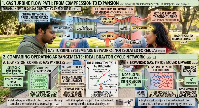
A unified engineering schematic mapping the physical layout of a gas turbine against its theoretical thermodynamic profile. The upper flow path traces the conversion of work and heat inputs into mechanical power output, while the lower T-s diagram tracks the precise state changes of the working fluid throughout the ideal Brayton cycle.
Infographic Breakdown: Gas Turbine Flow and Thermodynamic Cycle
This technical educational graphic provides a dual-layer analysis of a standard gas turbine system, linking the physical components directly to their thermodynamic cycle states.Panel 1: Macroscopic Gas Turbine Flow Path
The upper diagram illustrates the continuous, left-to-right fluid flow through the four core functional areas of the machine:- Air Inlet & Compressor: Ambient air enters the system from the far left. It passes into an axial compressor where its pressure and density increase. A clear arrow pointing into this stage signifies the required mechanical Work Input.
- Combustion Chamber: The high-pressure air moves into the combustor. A fuel energy source adds thermal energy to the fluid at a constant pressure, highlighted by a Heat Input (Qin) label.
- Turbine & Exhaust: The energized, high-temperature gas expands rapidly through the turbine blades, driving the shaft. This power generation phase is marked by a prominent, out-sized Work Output arrow, demonstrating net positive power before the remaining thermal energy exits via the exhaust.
Panel 2: Temperature-Entropy (T-s) Diagram
The lower diagram plots the ideal Brayton Cycle on a coordinate system with Temperature (T) on the vertical axis and Entropy (s) on the horizontal axis, mapping the machine’s operations to four distinct thermodynamic states:| Cycle Process | Thermodynamic Action | Corresponding Component |
|---|---|---|
| State 1 → 2 | Isentropic Compression (Vertical Temp Rise) | Axial Compressor (Work added, Entropy constant) |
| State 2 → 3 | Constant-Pressure Heat Addition (Isobaric curve) | Combustion Chamber (External heat Qin enters) |
| State 3 → 4 | Isentropic Expansion (Vertical Temp Drop) | Gas Turbine (Work extracted, Entropy constant) |
| State 4 → 1 | Constant-Pressure Heat Rejection (Isobaric curve) | Exhaust System / Environment (Waste heat cooling) |
The Four Ideal Processes of the Brayton Cycle
| Stage | Component or Process | Ideal Process | Main Event |
|---|---|---|---|
| 1 → 2 | Compressor | Isentropic compression | Air pressure and temperature rise |
| 2 → 3 | Combustor or heater | Constant-pressure heat addition | Heat is added and temperature rises strongly |
| 3 → 4 | Turbine | Isentropic expansion | Hot gas expands and produces work |
| 4 → 1 | Exhaust cooling or ideal heat rejection | Constant-pressure heat rejection | Heat is rejected to return to the starting state |
Process 1 → 2: Isentropic Compression
Process 2 → 3: Constant-Pressure Heat Addition
Process 3 → 4: Isentropic Expansion
Process 4 → 1: Constant-Pressure Heat Rejection
Energy Balance of the Brayton Cycle
| Quantity | Expression | Meaning |
|---|---|---|
| Compressor work input | wcompressor = cp(T2 − T1) | Work required to compress the air |
| Heat input | qin = cp(T3 − T2) | Heat added in the combustor or heater |
| Turbine work output | wturbine = cp(T3 − T4) | Work produced by hot gas expansion |
| Heat rejection | qout = cp(T4 − T1) | Heat rejected or carried away in the exhaust |
| Net work output | wnet = wturbine − wcompressor | Useful work after compressor work is subtracted |
Thermal Efficiency of the Ideal Brayton Cycle
| Symbol | Meaning | Role in Brayton Cycle |
|---|---|---|
| ηBrayton | Ideal thermal efficiency | Fraction of heat input converted into net work |
| rp | Pressure ratio | Major design variable affecting efficiency and work output |
| γ | Ratio of specific heats | Depends on gas properties |
| T3 | Turbine inlet temperature | Strongly affects work output and material limits |
Pressure Ratio and Turbine Inlet Temperature
| Design Variable | Ideal Benefit | Real Engineering Limit |
|---|---|---|
| Higher pressure ratio | Can improve ideal efficiency | Increases compressor work and may reduce net work beyond an optimum |
| Higher turbine inlet temperature | Can increase turbine work and power output | Limited by turbine blade materials, cooling, coatings, and emissions |
| Lower compressor inlet temperature | Can reduce compressor work | Depends on ambient conditions and inlet cooling feasibility |
| Lower turbine exhaust pressure | Can increase expansion work | Limited by exhaust system design and application |
The Brayton Cycle on a Temperature-Entropy Diagram
| Process | Appearance on T–S Diagram | Physical Meaning |
|---|---|---|
| 1 → 2 | Vertical upward line | Isentropic compression raises temperature |
| 2 → 3 | Heat-addition curve at high pressure | Temperature and entropy increase |
| 3 → 4 | Vertical downward line | Isentropic expansion produces work |
| 4 → 1 | Heat-rejection curve at low pressure | Temperature and entropy decrease |
The Brayton Cycle on a Pressure-Volume Diagram
| Process | Appearance on P–V Diagram | Meaning |
|---|---|---|
| 1 → 2 | Curved compression path | Pressure rises and volume decreases |
| 2 → 3 | Constant-pressure heating path | Volume increases as temperature rises |
| 3 → 4 | Curved expansion path | Pressure falls and volume increases |
| 4 → 1 | Constant-pressure cooling path | Volume decreases as temperature falls |
Open Brayton Cycle and Closed Brayton Cycle
| Cycle Type | How It Works | Example |
|---|---|---|
| Open Brayton Cycle | Fresh air enters, fuel burns, exhaust leaves | Jet engine or simple gas turbine |
| Closed Brayton Cycle | Same working fluid circulates through heater, turbine, cooler, and compressor | Some nuclear, solar, or specialised gas-cycle concepts |
| Air-standard model | Combustion and exhaust are replaced by heat addition and rejection | Ideal classroom Brayton Cycle analysis |
Main Components of a Gas Turbine Brayton System
Compressor
Raises air pressure before heat addition. It consumes a large fraction of turbine work, making compressor efficiency extremely important.
Combustor
Adds fuel and releases chemical energy at nearly constant pressure. It must provide stable combustion with acceptable pressure loss and emissions.
Turbine
Expands hot gas to produce work. Part of the work drives the compressor, and the remainder may produce shaft power or thrust.
Exhaust or Heat Recovery System
Releases hot gas or recovers exhaust energy in a regenerator, waste heat boiler, or combined-cycle plant.
Back Work Ratio in the Brayton Cycle
| Cycle | Compression Device | Back Work Ratio Tendency | Reason |
|---|---|---|---|
| Brayton Cycle | Compressor | Often large | Gas compression requires substantial work |
| Rankine Cycle | Pump | Usually small | Liquid water has small specific volume |
Regeneration in the Brayton Cycle
| Regeneration Feature | Function | Benefit |
|---|---|---|
| Regenerator or recuperator | Transfers heat from exhaust to compressed air | Reduces heat input required in combustor |
| Higher preheat temperature | Compressed air enters combustor warmer | Improves thermal efficiency |
| Lower exhaust heat loss | Less energy leaves unused | Supports fuel savings and waste heat recovery |
Intercooling and Reheating
Intercooling
Reheating
| Modification | Main Effect | Design Concern |
|---|---|---|
| Intercooling | Reduces compressor work | May increase required heat input unless regeneration is used |
| Reheating | Increases turbine work | Requires additional combustion or heating and may affect efficiency |
| Regeneration with intercooling and reheating | Can improve performance by recovering exhaust heat | Adds size, cost, pressure loss, and complexity |
Brayton Cycle Compared with Rankine Cycle
| Feature | Brayton Cycle | Rankine Cycle |
|---|---|---|
| Typical working fluid | Air or combustion gases | Water and steam |
| Phase change | No phase change in simple ideal cycle | Liquid-vapour phase change is central |
| Main compression device | Compressor | Pump |
| Compression work | Large | Small |
| Main applications | Gas turbines, jet engines, shaft power systems | Steam power plants and vapour power systems |
| Combined-cycle role | Topping cycle | Bottoming cycle using exhaust heat |
Brayton Cycle Compared with Otto and Diesel Cycles
| Feature | Otto Cycle | Diesel Cycle | Brayton Cycle |
|---|---|---|---|
| Typical machine | Spark-ignition piston engine | Compression-ignition piston engine | Gas turbine or jet engine |
| Flow type | Intermittent piston-cylinder process | Intermittent piston-cylinder process | Continuous-flow process |
| Heat addition model | Constant volume | Constant pressure | Constant pressure |
| Main design variable | Compression ratio | Compression ratio and cut-off ratio | Pressure ratio and turbine inlet temperature |
| Major application | Petrol engines | Diesel engines | Aircraft engines and gas turbine plants |
Applications of the Brayton Cycle
Aircraft Jet Engines
Turbojets, turbofans, and turboprops use Brayton-cycle principles to compress air, add fuel energy, expand gases, and produce thrust or shaft power.
Gas Turbine Power Plants
Gas turbines can generate electricity quickly and are useful for peak power, grid support, and combined-cycle plants.
Combined-Cycle Power Generation
Hot gas turbine exhaust can produce steam for a Rankine bottoming cycle, improving overall plant efficiency.
Marine Gas Turbines
Some ships use gas turbines where high power density and fast response are important.
Industrial Shaft Power
Gas turbines can drive compressors, pumps, generators, and industrial machinery.
Helicopter and Turboshaft Engines
Turboshaft engines use Brayton-cycle gas generators to drive rotor systems through shaft power.
Microturbines
Small gas turbines can provide distributed power, combined heat and power, or backup generation.
Closed-Cycle Gas Systems
Special Brayton cycles using helium, nitrogen, carbon dioxide, or other gases may support nuclear, solar, or advanced energy systems.
Combined-Cycle Power Plants
| Part of Combined Cycle | Main Function | Benefit |
|---|---|---|
| Brayton topping cycle | Gas turbine produces power from high-temperature combustion gases | Provides fast and high-temperature power generation |
| Heat recovery steam generator | Uses gas turbine exhaust heat to produce steam | Recovers energy that would otherwise be wasted |
| Rankine bottoming cycle | Steam turbine produces additional power | Improves overall plant efficiency |
Why Real Gas Turbines Differ from the Ideal Brayton Cycle
| Ideal Brayton Assumption | Real Gas Turbine Behaviour | Effect |
|---|---|---|
| Isentropic compression | Compressor losses, turbulence, and friction occur | Compressor work is higher than ideal |
| Constant-pressure heat addition | Combustor pressure drop occurs | Less pressure is available for turbine expansion |
| Isentropic expansion | Turbine losses and blade cooling occur | Turbine work is lower than ideal |
| Constant-pressure heat rejection | Open exhaust releases hot gas to surroundings | Exhaust heat may be wasted unless recovered |
| Constant specific heats | Gas properties vary strongly with temperature | Simple calculations may overpredict performance |
| No material limits | Turbine blades face extreme temperature and stress | Cooling, coatings, and advanced materials are required |
Materials, Cooling, and Turbine Blade Limits
| Thermal Challenge | Why It Matters | Engineering Response |
|---|---|---|
| High gas temperature | Can exceed material melting or creep limits | Use advanced superalloys and ceramic coatings |
| Blade cooling requirement | Cooling air protects blades but reduces cycle performance | Use internal cooling channels and film cooling carefully |
| Thermal stress | Temperature gradients can cause cracking or fatigue | Design for thermal expansion and cycling |
| Oxidation and corrosion | Hot gases can attack blade surfaces | Use protective coatings and suitable materials |
| Centrifugal stress | Blades rotate at high speed | Use strong materials and careful blade-root design |
Emissions and Combustion Challenges
| Combustion Challenge | Why It Occurs | Engineering Response |
|---|---|---|
| Nitrogen oxides | High combustion temperature encourages formation | Lean premixed combustion, staged combustion, water or steam injection, aftertreatment |
| Combustion instability | Pressure waves can couple with flame dynamics | Careful combustor design and active control |
| Pressure loss | Flow through combustor causes losses | Optimise combustor geometry and flow distribution |
| Fuel flexibility | Different fuels burn at different rates and temperatures | Adjust injection, mixing, control, and materials |
| High turbine inlet temperature | Improves performance but raises emissions and material stress | Balance efficiency, cooling, combustion design, and emissions limits |
Challenges and Practical Limitations
| Challenge | Why It Matters | Practical Consequence |
|---|---|---|
| Large compressor work | A significant fraction of turbine work drives the compressor | Compressor efficiency strongly affects net power |
| High turbine inlet temperature | Improves performance but stresses materials | Advanced cooling and materials are required |
| Pressure losses | Combustors, ducts, filters, and heat exchangers reduce useful pressure | Cycle performance falls below ideal predictions |
| Off-design operation | Engines operate at different loads, speeds, and ambient temperatures | Control systems and variable geometry may be needed |
| Emissions limits | Combustion produces pollutants depending on temperature and fuel | Low-emission combustors and aftertreatment may be required |
| Noise and exhaust temperature | Jet exhaust and turbine noise can be significant | Acoustic design and exhaust management matter |
| Cost and maintenance | Hot-section parts are expensive and highly stressed | Inspection, coatings, cooling, and replacement planning are essential |
Future Directions and Engineering Relevance
Hydrogen Gas Turbines
Hydrogen combustion may reduce carbon dioxide emissions, but it creates challenges in flame speed, nitrogen oxides, storage, and safety.
Supercritical Carbon Dioxide Brayton Cycles
Closed Brayton cycles using supercritical carbon dioxide may offer compact, efficient power conversion for advanced heat sources.
Advanced Turbine Materials
Ceramic matrix composites, superalloys, thermal barrier coatings, and additive manufacturing support higher-temperature operation.
Hybrid-Electric Aviation
Gas turbines may work with electric propulsion systems, batteries, or generators to improve aircraft efficiency and flexibility.
Carbon Capture Integration
Gas turbine systems may be paired with capture technologies or alternative combustion concepts to reduce emissions.
Digital Twin Monitoring
Real-time models can track compressor performance, turbine health, blade temperatures, emissions, and maintenance needs.
Combined Heat and Power
Gas turbines can supply electricity while useful exhaust heat supports industrial heating, district heating, or process steam.
Renewable Fuel Compatibility
Synthetic fuels, biofuels, ammonia, and hydrogen blends may change combustor and turbine design requirements.
Connections with Wider Thermodynamics
Thermodynamics
The Brayton Cycle applies energy balances, entropy, pressure ratio, and thermal efficiency to gas power systems.
Laws of Thermodynamics
The First Law gives the cycle energy balance, while the Second Law explains irreversibility and efficiency limits.
Heat Transfer
Blade cooling, combustor heat release, exhaust heat recovery, and thermal protection all depend on heat-transfer principles.
Engineering Thermodynamics
Gas turbines, compressors, combustors, turbines, nozzles, and power cycles are central engineering thermodynamics topics.
Fluid Mechanics and Hydraulics
Compressors, turbines, nozzles, boundary layers, losses, and turbomachinery all depend on fluid-flow behaviour.
Thermodynamics and Heat Transfer in Mechanical Engineering
The Brayton Cycle shows how thermal science supports engines, turbines, aircraft propulsion, power generation, and thermal design.
Learning Pathway Within Thermodynamic Cycles
Carnot Cycle
Learn how the ideal reversible heat-engine cycle sets the maximum possible efficiency between two temperatures.
Otto Cycle
Understand how the ideal spark-ignition engine cycle links compression ratio, constant-volume heat addition, expansion, and efficiency.
Diesel Cycle
Explore compression ignition, constant-pressure heat addition, cut-off ratio, and ideal diesel engine efficiency.
Rankine Cycle
Learn how steam power plants use pumps, boilers, turbines, condensers, phase change, and heat-to-work conversion.
Brayton Cycle
Current page. Understand gas turbines, jet engines, compressors, combustors, turbines, pressure ratio, and continuous-flow power.
Refrigeration and Heat Pump Cycles
See how reversed cycles use work input to move heat from colder regions to warmer regions.
Interactive Learning Tool: Ideal Brayton Cycle Performance Simulator
Brayton Cycle State & Efficiency Calculator (γ = 1.4, cp = 1.005 kJ/kg·K)
Quick Check: Brayton Cycle
Quick Check: Gas Turbines and Pressure Ratio
Key Terms
- Brayton Cycle
- An ideal gas power cycle used to model gas turbines, jet engines, and continuous-flow power systems.
- Gas turbine
- A machine that compresses air, adds heat by combustion or external heating, and expands hot gas through a turbine.
- Compressor
- A device that raises the pressure of air or gas, requiring work input.
- Combustor
- A chamber where fuel is burned to add heat to compressed air at approximately constant pressure.
- Turbine
- A machine that extracts work from expanding hot gas.
- Pressure ratio
- The compressor outlet pressure divided by compressor inlet pressure, written as rp = P2 / P1.
- Turbine inlet temperature
- The temperature of gas entering the turbine, often a major limit on power and efficiency.
- Back work ratio
- The ratio of compressor work input to turbine work output.
- Regeneration
- Recovery of exhaust heat to preheat compressed air before combustion or external heating.
- Intercooling
- Cooling between compressor stages to reduce total compressor work.
- Reheating
- Adding heat between turbine stages to increase turbine work output.
- Combined cycle
- A power plant arrangement that uses a Brayton topping cycle and a Rankine bottoming cycle to recover exhaust heat.
Frequently Asked Questions: Brayton Cycle
What is the Brayton Cycle?
What are the four processes of the Brayton Cycle?
What components are used in a simple gas turbine Brayton system?
What is the ideal Brayton Cycle efficiency formula?
What is pressure ratio?
Why is compressor work important?
How is the Brayton Cycle different from the Rankine Cycle?
How is the Brayton Cycle used in jet engines?
What is regeneration in the Brayton Cycle?
What is a combined-cycle power plant?
Why do real gas turbines differ from the ideal Brayton Cycle?
Why should students learn the Brayton Cycle?
Review Questions and Answers
- What is the Brayton Cycle?Answer: The Brayton Cycle is an ideal gas power cycle used to model gas turbines, jet engines, and continuous-flow power systems.
- What are the four ideal processes in the Brayton Cycle?Answer: The four ideal processes are isentropic compression, constant-pressure heat addition, isentropic expansion, and constant-pressure heat rejection.
- What does the compressor do?Answer: The compressor raises the pressure and temperature of incoming air, requiring work input.
- What does the combustor do?Answer: The combustor adds heat to compressed air, usually by burning fuel at approximately constant pressure.
- What does the turbine do?Answer: The turbine expands hot gas and produces work. Part of this work drives the compressor.
- What is pressure ratio?Answer: Pressure ratio is rp = P2 / P1, the compressor outlet pressure divided by compressor inlet pressure.
- What is the ideal Brayton efficiency equation?Answer: ηBrayton = 1 − [1 / (rp(γ − 1)/γ)].
- Why is the back work ratio important?Answer: It shows how much turbine work is consumed by the compressor. In gas turbines, this fraction can be large.
- How does the Brayton Cycle differ from the Rankine Cycle?Answer: The Brayton Cycle compresses and expands gas, while the Rankine Cycle pumps liquid and expands steam with phase change.
- Why do real Brayton engines fall below ideal performance?Answer: Real engines have compressor and turbine inefficiencies, pressure losses, heat losses, material limits, cooling requirements, emissions constraints, and off-design operation.
Thought-Provoking Questions and Answers
- Why is the Brayton Cycle especially suitable for aircraft propulsion?Answer: It supports continuous flow, high power density, fast gas expansion, and exhaust momentum, all of which are valuable for producing thrust and shaft power in aircraft engines.
- Why can increasing pressure ratio improve efficiency but still create design problems?Answer: Higher pressure ratio can improve ideal efficiency, but it increases compressor work, raises temperatures, complicates compressor design, and may reduce net work beyond an optimum.
- Why is turbine inlet temperature one of the most important limits in gas turbines?Answer: Higher turbine inlet temperature can increase work output, but turbine blades must survive extreme heat, stress, oxidation, and cooling demands.
- Why does a combined-cycle plant use both Brayton and Rankine cycles?Answer: The Brayton gas turbine produces power first, and its hot exhaust then drives a Rankine steam cycle, recovering heat that would otherwise be wasted.
- Why does regeneration not always help a Brayton Cycle?Answer: Regeneration helps only when turbine exhaust temperature is higher than compressor outlet temperature. Otherwise, little useful heat can be recovered.
- Why is the Brayton Cycle a strong example of the link between thermodynamics and fluid mechanics?Answer: Its performance depends not only on energy balances, but also on compressor aerodynamics, turbine blade flow, pressure losses, nozzles, ducts, and combustion flow.
- Why might hydrogen gas turbines be promising but difficult?Answer: Hydrogen can reduce carbon dioxide emissions at combustion, but it burns differently from natural gas and raises challenges in flame speed, nitrogen oxides, safety, storage, and combustor design.
- What does the Brayton Cycle teach about engineering trade-offs?Answer: It shows that efficiency, power, pressure ratio, turbine temperature, emissions, materials, cooling, cost, and reliability must be balanced together rather than optimised separately.
Numerical Problems and Solutions
- An ideal Brayton Cycle has pressure ratio rp = 8 and γ = 1.4. Find the ideal thermal efficiency.Solution:
- Use ηBrayton = 1 − [1 / (rp(γ − 1)/γ)].
- (γ − 1) / γ = 0.4 / 1.4 ≈ 0.286.
- rp0.286 = 80.286 ≈ 1.81.
- ηBrayton = 1 − (1 / 1.81).
- ηBrayton ≈ 1 − 0.552 = 0.448.
Answer: The ideal thermal efficiency is approximately 44.8%. - An ideal Brayton Cycle has T1 = 300 K, rp = 10, and γ = 1.4. Find T2 after isentropic compression.Solution:
- Use T2 / T1 = rp(γ − 1)/γ.
- rp0.286 = 100.286 ≈ 1.93.
- T2 = (300)(1.93).
- T2 ≈ 579 K.
Answer: The compressor outlet temperature is approximately 579 K. - An ideal Brayton Cycle has T3 = 1400 K, rp = 10, and γ = 1.4. Find T4 after isentropic expansion.Solution:
- For equal pressure ratios, T3 / T4 = rp(γ − 1)/γ.
- rp0.286 ≈ 1.93.
- T4 = T3 / 1.93 = 1400 / 1.93.
- T4 ≈ 725 K.
Answer: The turbine exit temperature is approximately 725 K. - A Brayton Cycle has cp = 1.005 kJ/(kg·K), T1 = 300 K, T2 = 580 K, T3 = 1400 K, and T4 = 725 K. Find compressor work, turbine work, net work, and heat input per kilogram.Solution:
- Compressor work: wcompressor = cp(T2 − T1) = 1.005(580 − 300).
- wcompressor ≈ 281.4 kJ/kg.
- Turbine work: wturbine = cp(T3 − T4) = 1.005(1400 − 725).
- wturbine ≈ 678.4 kJ/kg.
- Net work: wnet = 678.4 − 281.4 = 397.0 kJ/kg.
- Heat input: qin = cp(T3 − T2) = 1.005(1400 − 580).
- qin ≈ 824.1 kJ/kg.
Answer: wcompressor ≈ 281.4 kJ/kg, wturbine ≈ 678.4 kJ/kg, wnet ≈ 397.0 kJ/kg, and qin ≈ 824.1 kJ/kg. - Using the values from the previous problem, find the Brayton Cycle efficiency.Solution:
- Use η = wnet / qin.
- η = 397.0 / 824.1.
- η ≈ 0.482.
Answer: The cycle efficiency is approximately 48.2%. - A Brayton Cycle has compressor work 300 kJ/kg and turbine work 750 kJ/kg. Find the net work and back work ratio.Solution:
- Net work: wnet = 750 − 300 = 450 kJ/kg.
- Back work ratio: BWR = 300 / 750 = 0.40.
Answer: The net work is 450 kJ/kg, and the back work ratio is 0.40, or 40%. - A gas turbine produces net work of 400 kJ/kg. If the mass flow rate is 25 kg/s, find the net power output.Solution:
- Use Ẇnet = ṁ wnet.
- Ẇnet = (25)(400) = 10000 kJ/s.
- Since 1 kJ/s = 1 kW, Ẇnet = 10000 kW.
Answer: The net power output is 10 MW. - A regenerator raises compressed air temperature from 600 K to 850 K before combustion. If cp = 1.005 kJ/(kg·K), estimate the heat saved per kilogram.Solution:
- Heat saved is approximately qsaved = cp(Tafter − Tbefore).
- qsaved = 1.005(850 − 600).
- qsaved ≈ 251.25 kJ/kg.
Answer: The regenerator saves approximately 251 kJ/kg of heat input.