
The Diesel Cycle is the ideal thermodynamic cycle used to understand compression-ignition diesel engines. It models how air is compressed to a high temperature, heat is added at nearly constant pressure, the hot gas expands to produce work, and heat is finally rejected to complete the cycle.
This page belongs to the Thermodynamic Cycles cluster within Thermodynamics. It follows the Carnot Cycle, which sets the ideal efficiency limit, and the Otto Cycle, which models spark-ignition petrol engines. It also prepares students for larger power and flow cycles such as the Rankine Cycle, Brayton Cycle, and Refrigeration and Heat Pump Cycles.
The central idea of the Diesel Cycle is different from the Otto Cycle. In the ideal Otto Cycle, heat is added at constant volume. In the ideal Diesel Cycle, heat is added at constant pressure. This difference reflects the way diesel engines operate: air is compressed first, fuel is injected into the hot compressed air, and ignition occurs because the air temperature is high enough for combustion without a spark plug.
The Diesel Cycle is not a perfect picture of a real diesel engine. Real diesel combustion is complex, time-dependent, turbulent, chemically reactive, and affected by fuel injection, spray formation, air motion, heat loss, emissions, and mechanical design. Even so, the ideal Diesel Cycle gives students a clear first model for understanding compression ignition, cut-off ratio, work output, and thermal efficiency.
Interactive Diesel Cycle Calculator & Simulator
Explore how compression ratio (r) and cut-off ratio (rc) influence thermal efficiency, peak pressures, temperatures, and net work output. Adjust the parameters below to dynamically update the ideal cycle calculations and visual PV diagram.
THERMAL EFFICIENCY (η)
61.4%
PEAK TEMP (T3)
1818 K
COMP. TEMP (T2)
909 K
EXP. TEMP (T4)
701 K
What the Diesel Cycle Really Is
The Diesel Cycle is an ideal air-standard cycle associated with compression-ignition engines. In the simplified model, the working fluid is treated as air, the combustion process is replaced by heat addition at constant pressure, and the exhaust process is replaced by heat rejection at constant volume.
In a real diesel engine, only air is compressed during the compression stroke. Fuel is injected near the end of compression, when the air is already hot enough to ignite the fuel. This is why diesel engines do not require spark plugs in the same way spark-ignition petrol engines do.
| Feature | Diesel Cycle Meaning | Real Engine Connection |
|---|---|---|
| Compression ignition | Air is compressed until it becomes very hot | Fuel ignites after injection into hot compressed air |
| Constant-pressure heat addition | Heat is added while pressure remains idealised as constant | Approximates part of the combustion process during piston movement |
| High compression ratio | The cycle relies on strong compression before heat addition | Diesel engines usually use higher compression ratios than petrol engines |
| Cut-off ratio | Describes how long heat addition continues during expansion | Related to fuel injection duration and combustion timing |
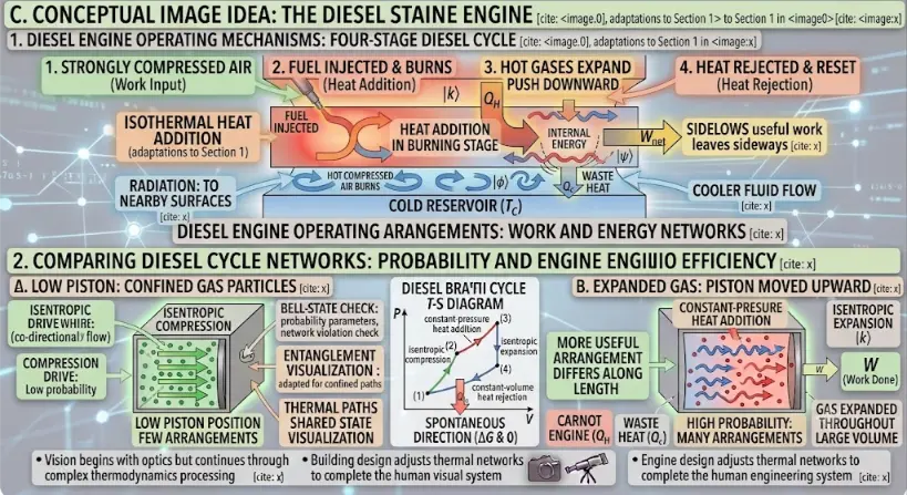
Conceptual visualization of the four-stage Diesel cycle, connecting operating mechanisms and microscopic states. The top panel illustrates a natural, multi-mode flow loop driven by work input and spontaneous heat addition. The lower panels track useful work and cycle efficiency spontaneity.
The Four Ideal Processes of the Diesel Cycle
The ideal Diesel Cycle consists of four internally reversible processes. Two are isentropic processes, one is a constant-pressure heat-addition process, and one is a constant-volume heat-rejection process.
| Stage | Process | Main Event | Heat or Work Meaning |
|---|---|---|---|
| 1 → 2 | Isentropic compression | Air is compressed to high pressure and temperature | Work is done on the air |
| 2 → 3 | Constant-pressure heat addition | Heat is added while volume increases | Represents idealised fuel combustion |
| 3 → 4 | Isentropic expansion | Hot gas expands and produces useful work | Main power-producing process |
| 4 → 1 | Constant-volume heat rejection | Heat is rejected at fixed volume | Returns the working fluid toward its initial state |
Process 1 → 2: Isentropic Compression
The air is compressed without heat transfer and without internal irreversibility in the ideal model. Its volume decreases, while pressure and temperature increase sharply.
For an ideal gas with constant specific heats:
T2 / T1 = rγ − 1
P2 / P1 = rγ
Here, r is the compression ratio, and γ is the ratio of specific heats.
Process 2 → 3: Constant-Pressure Heat Addition
Heat is added while pressure remains constant in the ideal model. Unlike the Otto Cycle, where heat addition occurs at constant volume, the Diesel Cycle allows volume to increase during heat addition.
This ideal process reflects the fact that fuel injection and combustion in a real diesel engine continue for a finite time while the piston is already moving downward.
For the ideal air-standard Diesel Cycle:
Qin = m cp (T3 − T2)
Process 3 → 4: Isentropic Expansion
The hot high-pressure gas expands and produces work. This is the main power-producing part of the cycle. In the ideal model, expansion is isentropic, so there is no heat transfer and no entropy generation.
For the isentropic expansion process:
T3 V3γ − 1 = T4 V4γ − 1
The expansion process converts part of the thermal energy of the hot gas into useful mechanical work.
Process 4 → 1: Constant-Volume Heat Rejection
Heat is rejected while volume remains constant, returning the working fluid toward its initial state in the ideal cycle.
For the ideal air-standard Diesel Cycle:
Qout = m cv (T4 − T1)
In a real diesel engine, this step is an idealised replacement for exhaust and intake processes. The real engine does not keep the same mass of air cycling forever; it expels exhaust gases and takes in fresh air.
The Diesel Cycle on a Pressure-Volume Diagram
On a pressure-volume diagram, the Diesel Cycle appears as a closed loop. The area inside the loop represents the net work output per cycle.
| Process | Appearance on P–V Diagram | Meaning |
|---|---|---|
| 1 → 2 | Curved compression path | Volume decreases while pressure rises sharply |
| 2 → 3 | Horizontal line to the right | Heat is added at constant pressure while volume increases |
| 3 → 4 | Curved expansion path | Gas expands and produces work |
| 4 → 1 | Vertical line downward | Heat is rejected at constant volume |
The key visual difference from the Otto Cycle is the heat-addition step. In the Otto Cycle, heat addition is a vertical line at constant volume. In the Diesel Cycle, heat addition is a horizontal line at constant pressure.
The Diesel Cycle on a Temperature-Entropy Diagram
On a temperature-entropy diagram, the isentropic compression and expansion processes appear as vertical lines. The constant-pressure heat-addition process increases both temperature and entropy, while the constant-volume heat-rejection process reduces temperature and entropy.
| Process | Path on T–S Diagram | Thermal Meaning |
|---|---|---|
| 1 → 2 | Vertical upward path | Isentropic compression raises temperature |
| 2 → 3 | Heat-addition path at constant pressure | Heat is supplied and entropy increases |
| 3 → 4 | Vertical downward path | Isentropic expansion lowers temperature |
| 4 → 1 | Heat-rejection path at constant volume | Heat is rejected and entropy decreases |
The T–S diagram helps students connect heat addition and rejection with entropy change. It also prepares them for later cycles, especially the Rankine and Brayton cycles, where temperature-entropy diagrams are widely used.
Compression Ratio
The compression ratio is the ratio of maximum volume to minimum volume:
r = V1 / V2
Diesel engines generally use high compression ratios because compression must raise the air temperature enough for fuel to ignite after injection.
| Compression Ratio Effect | Ideal Diesel Cycle Result | Real Diesel Engine Concern |
|---|---|---|
| Higher r | Can improve ideal thermal efficiency | Increases peak pressure, stress, and structural demands |
| Lower r | May reduce ideal efficiency | May make reliable compression ignition more difficult |
| Very high r | Attractive thermodynamically | Limited by materials, noise, emissions, and engine weight |
Cut-Off Ratio
The cut-off ratio is a special feature of the Diesel Cycle. It describes how much the volume increases during the constant-pressure heat-addition process:
rc = V3 / V2
Here, V2 is the volume at the start of heat addition, and V3 is the volume at the end of heat addition.
A larger cut-off ratio means heat addition continues over a longer part of the expansion. This can increase work output, but it can also reduce ideal efficiency for a fixed compression ratio.
| Cut-Off Ratio Change | Ideal Meaning | Real Engine Interpretation |
|---|---|---|
| Small rc | Heat addition ends earlier | Shorter fuel injection duration in idealised terms |
| Larger rc | Heat addition continues longer during expansion | More fuel energy added over a longer part of piston travel |
| Very large rc | May reduce ideal efficiency for fixed r | Can increase exhaust temperature and affect emissions |
Thermal Efficiency of the Diesel Cycle
The thermal efficiency of any heat-engine cycle is:
η = Wnet / Qin
Since:
Wnet = Qin − Qout
the efficiency may also be written as:
η = 1 − (Qout / Qin)
For the ideal air-standard Diesel Cycle with constant specific heats:
ηDiesel = 1 − [ 1 / rγ − 1 ] × [ (rcγ − 1) / (γ (rc − 1)) ]
| Symbol | Meaning | Role in Efficiency |
|---|---|---|
| ηDiesel | Ideal Diesel Cycle thermal efficiency | Fraction of heat input converted into net work |
| r | Compression ratio | Higher r tends to increase ideal efficiency |
| rc | Cut-off ratio | Larger rc tends to reduce ideal efficiency for fixed r |
| γ | Ratio of specific heats | Depends on gas properties and temperature range |
This formula shows why the Diesel Cycle is controlled not only by compression ratio but also by cut-off ratio. That makes it more complex than the ideal Otto Cycle efficiency formula.
Why Diesel Engines Use High Compression Ratios
A diesel engine compresses air before fuel is injected. The compressed air must become hot enough to ignite the fuel. This requires a high compression ratio.
High compression ratio can also improve thermal efficiency because the cycle operates over a larger temperature range. However, it increases peak pressure and mechanical loading, so the engine must be built stronger.
| Benefit of High Compression Ratio | Cost or Limitation | Engineering Response |
|---|---|---|
| Reliable compression ignition | High pressure and stress | Use stronger engine blocks, pistons, bearings, and connecting rods |
| Improved ideal efficiency | More demanding thermal management | Improve cooling systems and materials |
| Better low-speed torque potential | Higher engine weight and noise | Optimise structure, combustion, and control |
| Good fuel economy | Emissions challenges | Use fuel injection control and exhaust aftertreatment |
Air-Standard Assumptions
The Diesel Cycle is usually introduced using air-standard assumptions. These assumptions simplify analysis, but they also mark the difference between the ideal model and real diesel engines.
| Air-Standard Assumption | Simplification | Real Diesel Engine Behaviour |
|---|---|---|
| Working fluid is air | Air circulates in a closed loop | Real engines take in air, inject fuel, burn it, and exhaust combustion products |
| Combustion becomes heat addition | Heat is added at constant pressure | Real combustion depends on spray, mixing, ignition delay, turbulence, and chemistry |
| Exhaust becomes heat rejection | Heat is rejected at constant volume | Real exhaust gases leave the cylinder and fresh air enters |
| Compression and expansion are isentropic | No friction, heat loss, leakage, or turbulence | Real engines generate entropy and lose heat to walls |
| Specific heats are constant | cp, cv, and γ are fixed | Specific heats vary with temperature and gas composition |
Diesel Cycle and the Four-Stroke Diesel Engine
The Diesel Cycle is related to the four-stroke diesel engine, but it is not the same as the mechanical stroke sequence. The four-stroke diesel engine has intake, compression, power, and exhaust strokes. The ideal Diesel Cycle focuses on the thermodynamic state changes of an ideal working fluid.
| Real Four-Stroke Diesel Event | Thermodynamic Meaning | Connection with Diesel Cycle |
|---|---|---|
| Intake stroke | Air enters the cylinder | Not represented directly in the closed ideal cycle |
| Compression stroke | Air is compressed to high temperature | Approximated by isentropic compression, 1 → 2 |
| Fuel injection and combustion | Fuel burns in hot compressed air | Approximated by constant-pressure heat addition, 2 → 3 |
| Power stroke | Hot gases expand and push the piston | Approximated by isentropic expansion, 3 → 4 |
| Exhaust stroke | Combustion products leave the cylinder | Idealised as heat rejection and cycle reset, 4 → 1 |
Diesel Cycle Versus Otto Cycle
The Diesel Cycle and Otto Cycle are both ideal air-standard cycles for internal combustion engines, but they model different ignition and heat-addition behaviour.
| Feature | Otto Cycle | Diesel Cycle |
|---|---|---|
| Typical engine association | Spark-ignition petrol engine | Compression-ignition diesel engine |
| Ideal heat addition | Constant volume | Constant pressure |
| Ignition method | Spark plug ignites fuel-air mixture | Fuel ignites after injection into hot compressed air |
| Main efficiency variables | Compression ratio and γ | Compression ratio, cut-off ratio, and γ |
| Typical compression ratio | Lower than diesel engine | Higher than petrol engine |
| Real engine issue | Knocking limits compression ratio | Peak pressure, emissions, fuel injection, and noise are major concerns |
For the same compression ratio, the ideal Otto Cycle is usually more efficient than the ideal Diesel Cycle. However, real diesel engines often use much higher compression ratios, which is one reason they can achieve strong fuel economy in practice.
Diesel Cycle Versus Carnot Cycle
The Carnot Cycle gives the ideal upper limit for any heat engine operating between two temperature reservoirs. The Diesel Cycle is a practical idealisation of a compression-ignition engine. They serve different purposes.
| Feature | Carnot Cycle | Diesel Cycle |
|---|---|---|
| Main purpose | Defines maximum possible efficiency | Models compression-ignition engine behaviour |
| Heat addition | Isothermal | Constant pressure |
| Heat rejection | Isothermal | Constant volume |
| Practical engine closeness | Very ideal and not engine-specific | Closer to real diesel engine analysis |
| Main lesson | Efficiency is limited by temperature reservoirs | Efficiency depends on compression ratio and cut-off ratio |
Mean Effective Pressure
Mean effective pressure gives a useful way to compare piston-engine cycles. It is the average pressure that would produce the same net work over the displacement volume.
A common definition is:
MEP = Wnet / (V1 − V2)
This quantity helps compare engines of different sizes because it relates work output to displacement volume rather than total cylinder volume alone.
| Quantity | Meaning | Why It Matters |
|---|---|---|
| MEP | Equivalent average pressure producing net work | Useful for comparing engine cycles |
| Wnet | Net work per cycle | Related to power output |
| V1 − V2 | Displacement volume in the ideal model | Represents the swept volume of the piston |
Applications of the Diesel Cycle
The Diesel Cycle is useful because it gives a first model for compression-ignition engine behaviour. It helps students and engineers reason about high compression, fuel injection, heat addition, expansion work, and efficiency.
Diesel Engine Analysis
The Diesel Cycle provides a first thermodynamic model for compression-ignition engines used in vehicles, generators, ships, and machinery.Heavy-Duty Transport
Trucks, buses, trains, ships, and heavy equipment often use diesel engines because of torque, durability, and fuel economy.Power Generation
Diesel generators are used for backup power, remote power supply, construction sites, hospitals, and emergency systems.Compression Ratio Design
The cycle shows why high compression ratio matters for ignition and efficiency, while also increasing pressure and stress.Fuel Injection Strategy
The ideal cut-off ratio introduces the idea that fuel addition duration affects work output and efficiency.Engine Performance Comparison
The cycle helps compare ideal work, efficiency, mean effective pressure, and heat rejection across engine designs.Alternative Diesel Fuels
Biodiesel, synthetic diesel, renewable diesel, and blended fuels can be discussed using diesel-cycle concepts.Emissions and Efficiency Studies
The cycle gives a baseline for understanding trade-offs among fuel economy, peak temperature, emissions, and aftertreatment.Why Real Diesel Engines Differ from the Ideal Diesel Cycle
Real diesel engines do not follow the ideal Diesel Cycle exactly. The ideal cycle is useful because it isolates the main thermodynamic pattern, but real engines involve many additional effects.
| Ideal Diesel Cycle Assumption | Real Diesel Engine Behaviour | Effect |
|---|---|---|
| Isentropic compression | Heat loss, friction, turbulence, and leakage occur | Compression is less ideal |
| Constant-pressure heat addition | Combustion pressure varies during injection and burning | Heat addition is not perfectly horizontal on a P–V diagram |
| Isentropic expansion | Heat is lost to cylinder walls and flow losses occur | Work output is reduced |
| Constant-volume heat rejection | Exhaust valve opens and gases leave the cylinder | Real exhaust process differs from ideal heat rejection |
| Closed air cycle | Air enters, fuel is injected, and exhaust leaves | Mass and composition change during operation |
| No emissions chemistry | Real combustion produces pollutants depending on conditions | Design must balance efficiency and emissions |
Emissions, Noise, and Combustion Challenges
Diesel engines are valued for efficiency and durability, but real diesel combustion brings important challenges. High temperature and pressure can support efficient combustion, yet they also influence nitrogen oxides, soot formation, noise, vibration, and aftertreatment requirements.
| Challenge | Why It Happens | Engineering Response |
|---|---|---|
| Nitrogen oxides | High combustion temperature encourages formation | Exhaust gas recirculation, combustion control, selective catalytic reduction |
| Soot and particulates | Fuel-rich regions may burn incompletely | Better fuel injection, air mixing, particulate filters |
| Diesel knock and noise | Rapid pressure rise after ignition delay | Control injection timing, pilot injection, chamber design |
| High peak pressure | Strong compression and combustion loading | Stronger components and improved pressure control |
| Cold starting | Low temperature makes ignition harder | Glow plugs, intake heating, improved fuels, control strategies |
| Aftertreatment complexity | Emissions must be reduced before exhaust release | Catalysts, filters, sensors, and control systems |
These challenges show why diesel engineering is not only a question of cycle efficiency. It is also a problem of combustion, materials, emissions, controls, fuels, and public health regulation.
Improving Diesel Engine Performance
Engineers improve diesel engine performance by managing compression, injection, air supply, combustion, heat transfer, friction, and exhaust treatment together.
Optimised Fuel Injection
Modern injection systems control timing, pressure, spray pattern, and multiple injection events to improve combustion.Turbocharging
Turbochargers increase air supply, improve power density, and recover some exhaust energy.Intercooling
Cooling compressed intake air increases density and helps manage combustion temperature.Reduced Friction
Better lubricants, coatings, bearings, and piston designs reduce mechanical losses.Improved Thermal Management
Cooling systems protect components while avoiding unnecessary heat loss from the working gases.Exhaust Aftertreatment
Particulate filters, catalysts, and selective catalytic reduction systems reduce harmful emissions.Alternative Fuels
Biodiesel, renewable diesel, synthetic diesel, and dual-fuel systems may reduce lifecycle emissions under suitable conditions.Digital Engine Control
Sensors and control algorithms adjust injection, boost, exhaust recirculation, and aftertreatment in real time.Challenges and Practical Limitations
The Diesel Cycle is simple enough for first analysis, but real diesel engines involve many limitations that the ideal model does not fully capture.
| Challenge | Why It Matters | Practical Consequence |
|---|---|---|
| Combustion is not perfectly constant pressure | Fuel injection and burning occur over time and space | Real pressure curves differ from the ideal cycle |
| Specific heats vary | High-temperature gases do not keep constant cp, cv, and γ | Simple calculations may overestimate efficiency |
| Heat losses occur | Cylinder walls, piston, head, and coolant absorb heat | Expansion work is reduced |
| Mechanical friction exists | Moving components dissipate energy | Brake power is lower than ideal indicated work |
| High pressure requires strong structure | Compression ignition creates demanding loads | Engines may be heavier and more expensive |
| Emissions limits are strict | Combustion products affect air quality | Aftertreatment and control systems are essential |
| Transient operation is complex | Load, speed, injection, boost, and temperature change continuously | Steady ideal-cycle analysis is only a starting point |
Future Directions and Engineering Relevance
The Diesel Cycle remains important even as energy systems change. Diesel engines continue to appear in heavy transport, ships, backup power, construction equipment, agriculture, and remote power systems. At the same time, emissions and decarbonisation pressures are reshaping diesel technology.
Cleaner Combustion
Improved injection, combustion chamber design, and air management can reduce soot and improve efficiency.Renewable Diesel and Biodiesel
Alternative fuels may reduce lifecycle carbon impact when production pathways are sustainable.Hybrid Diesel Systems
Hybridisation can let diesel engines operate closer to efficient regions while electric systems handle transients.Waste Heat Recovery
Exhaust energy can sometimes be recovered using turbo-compounding, secondary cycles, or thermoelectric systems.Advanced Aftertreatment
Better catalysts, filters, sensors, and controls help reduce pollutants from diesel exhaust.Digital Twin Monitoring
Real-time engine models can support maintenance, fuel optimisation, emissions control, and fault detection.Hydrogen and Dual-Fuel Concepts
Some future engines may combine compression ignition ideas with alternative fuels and new combustion modes.Heavy-Duty Decarbonisation
Diesel-cycle understanding remains useful when comparing electrification, hydrogen, synthetic fuels, and hybrid systems.Connections with Wider Thermodynamics
The Diesel Cycle connects thermodynamics with heat transfer, combustion, engine design, fuel technology, emissions, and mechanical engineering. It shows how ideal cycle analysis can clarify a real technology without pretending to capture every detail.
Thermodynamics
The Diesel Cycle applies energy conservation and ideal process models to compression-ignition heat engines.Laws of Thermodynamics
The First Law gives the cycle energy balance, while the Second Law explains efficiency limits and irreversibility.Heat Transfer
Real diesel engines lose heat to cylinder walls, coolant, exhaust, turbochargers, and surrounding structures.Engineering Thermodynamics
Diesel engines, compression ignition, efficiency, and power cycles are central engineering thermodynamics topics.Automotive Engineering
The Diesel Cycle provides a first model for compression-ignition engines used in transport, machinery, and power generation.Thermodynamics and Heat Transfer in Mechanical Engineering
The Diesel Cycle shows how thermal science supports engine design, fuel efficiency, combustion control, and emissions reduction.Learning Pathway Within Thermodynamic Cycles
The Diesel Cycle is the third page in this Thermodynamic Cycles pathway. After studying the Carnot efficiency limit and the Otto Cycle for spark-ignition engines, students now examine compression-ignition engines and constant-pressure heat addition.
Carnot Cycle
Learn how the ideal reversible heat-engine cycle sets the maximum possible efficiency between two temperatures.Otto Cycle
Understand how the ideal spark-ignition engine cycle links compression ratio, constant-volume heat addition, expansion, and efficiency.Diesel Cycle
Current page. Explore compression ignition, constant-pressure heat addition, cut-off ratio, and ideal diesel engine efficiency.Rankine Cycle
Learn how steam power plants use boilers, turbines, condensers, pumps, and phase change to produce work.Brayton Cycle
Understand the gas turbine and jet engine cycle involving compression, combustion, expansion, and exhaust.Refrigeration and Heat Pump Cycles
See how reversed cycles use work input to move heat from colder regions to warmer regions.Quick Check: Diesel Cycle
Quick Check: Compression Ignition and Cut-Off Ratio
Q1. What type of real engine does the Diesel Cycle idealise?
The Diesel Cycle idealises a compression-ignition diesel engine.
Q2. During which Diesel Cycle process is heat added?
Heat is added during the constant-pressure process from state 2 to state 3.
Q3. What does the cut-off ratio describe?
The cut-off ratio describes how much the volume increases during constant-pressure heat addition: rc = V3 / V2.
Q4. Why do diesel engines use high compression ratios?
They use high compression ratios to raise air temperature enough for fuel to ignite after injection.
Key Terms
- Diesel Cycle
- An ideal air-standard cycle used to model compression-ignition diesel engines.
- Compression-ignition engine
- An engine in which fuel ignites after being injected into hot compressed air.
- Compression ratio
- The ratio of maximum volume to minimum volume, written as r = V1 / V2.
- Cut-off ratio
- The ratio rc = V3 / V2, describing volume increase during constant-pressure heat addition.
- Isentropic compression
- Ideal reversible adiabatic compression with constant entropy.
- Constant-pressure heat addition
- The ideal Diesel Cycle process in which heat is added while pressure remains constant.
- Isentropic expansion
- Ideal reversible adiabatic expansion that produces work while entropy remains constant.
- Constant-volume heat rejection
- The ideal Diesel Cycle process in which heat is rejected while volume remains fixed.
- Thermal efficiency
- The fraction of heat input converted into net work output.
- Fuel injection
- The process of delivering fuel into the compressed air inside a diesel engine cylinder.
- Ignition delay
- The short delay between fuel injection and the start of combustion.
- Mean effective pressure
- An average pressure measure that relates net work output to displacement volume.
Frequently Asked Questions: Diesel Cycle
What is the Diesel Cycle?
The Diesel Cycle is an ideal thermodynamic cycle used to model compression-ignition diesel engines.
What are the four processes of the Diesel Cycle?
The four processes are isentropic compression, constant-pressure heat addition, isentropic expansion, and constant-volume heat rejection.
What type of engine is the Diesel Cycle associated with?
It is associated mainly with compression-ignition engines, where fuel ignites after being injected into hot compressed air.
How is the Diesel Cycle different from the Otto Cycle?
The Diesel Cycle assumes constant-pressure heat addition, while the Otto Cycle assumes constant-volume heat addition.
What is the Diesel Cycle efficiency formula?
For the ideal air-standard Diesel Cycle with constant specific heats, ηDiesel = 1 − [ 1 / rγ − 1 ] × [ (rcγ − 1) / (γ (rc − 1)) ].
What is compression ratio in the Diesel Cycle?
Compression ratio is r = V1 / V2, the ratio of maximum volume before compression to minimum volume after compression.
What is cut-off ratio in the Diesel Cycle?
Cut-off ratio is rc = V3 / V2, the ratio of volume after heat addition to volume before heat addition.
Why do diesel engines usually have higher compression ratios than petrol engines?
Diesel engines must compress air to a high enough temperature for fuel to ignite after injection, so high compression ratio is essential.
Does a real diesel engine follow the ideal Diesel Cycle exactly?
No. Real diesel engines include fuel injection, combustion chemistry, heat loss, friction, turbulence, emissions, changing gas composition, intake, and exhaust processes.
Why is diesel combustion challenging?
Diesel combustion involves fuel spray, air mixing, ignition delay, high pressure, high temperature, emissions formation, and combustion noise.
What does the area inside the Diesel Cycle P–V diagram represent?
The area inside the cycle loop represents the net work output per cycle.
Why should students learn the Diesel Cycle?
The Diesel Cycle helps students understand compression ignition, high compression ratio, constant-pressure heat addition, cut-off ratio, efficiency, and real engine limitations.
Review Questions and Answers
- What is the Diesel Cycle?Answer: The Diesel Cycle is an ideal air-standard thermodynamic cycle used to model compression-ignition diesel engines.
- What are the four processes in the ideal Diesel Cycle?Answer: The four processes are isentropic compression, constant-pressure heat addition, isentropic expansion, and constant-volume heat rejection.
- How is heat added in the ideal Diesel Cycle?Answer: Heat is added at constant pressure from state 2 to state 3.
- What is the compression ratio?Answer: The compression ratio is r = V1 / V2, the ratio of maximum volume to minimum volume.
- What is the cut-off ratio?Answer: The cut-off ratio is rc = V3 / V2, the ratio of volume after heat addition to volume before heat addition.
- Why do diesel engines use high compression ratios?Answer: High compression ratio raises air temperature enough for injected fuel to ignite without a spark plug.
- How does the Diesel Cycle differ from the Otto Cycle?Answer: The Diesel Cycle uses constant-pressure heat addition, while the Otto Cycle uses constant-volume heat addition.
- Why can real diesel engines not follow the ideal Diesel Cycle exactly?Answer: Real diesel engines have heat loss, friction, fuel injection delay, combustion complexity, turbulence, emissions, intake, exhaust, and changing gas composition.
- What does mean effective pressure measure?Answer: Mean effective pressure is an equivalent average pressure that would produce the same net work over the displacement volume.
- Why is the Diesel Cycle important in engineering education?Answer: It gives students a clear ideal model for compression-ignition engines, high compression ratios, cut-off ratio, and engine efficiency.
Thought-Provoking Questions and Answers
- Why is the Diesel Cycle useful even though real diesel engines are more complex?Answer: The ideal cycle isolates the main thermodynamic structure: compression, heat addition, expansion, and heat rejection. This gives students a foundation before adding real combustion, emissions, and mechanical losses.
- Why does compression ignition change the design philosophy of an engine?Answer: Compression ignition requires the air to become hot enough for fuel ignition, so compression ratio, injection timing, fuel spray, and combustion chamber design become central issues.
- Why can a diesel engine be efficient but still environmentally challenging?Answer: High efficiency reduces fuel use, but high-temperature combustion and fuel-rich regions can produce nitrogen oxides and particulates that require careful control and aftertreatment.
- Why does cut-off ratio matter in the Diesel Cycle?Answer: Cut-off ratio affects how long heat addition continues during expansion, influencing work output, heat rejection, and ideal thermal efficiency.
- Why might diesel engines remain relevant even as vehicles become more electrified?Answer: Heavy transport, ships, generators, remote power, construction machinery, agriculture, and hybrid systems may still use diesel or diesel-like engines where energy density and durability matter.
- Why is the Diesel Cycle a good example of the difference between model and reality?Answer: The model uses clean ideal processes, while the real engine involves spray, mixing, combustion chemistry, emissions, heat transfer, friction, and control systems.
- How does the Diesel Cycle connect efficiency with structural design?Answer: High compression ratio can improve efficiency and enable ignition, but it also increases pressure and stress, requiring stronger and often heavier components.
- What does diesel engine development teach about engineering trade-offs?Answer: It shows that efficiency, emissions, noise, durability, cost, fuel type, and power output must be balanced rather than optimised separately.
Numerical Problems and Solutions
- An ideal Diesel Cycle has compression ratio r = 16, cut-off ratio rc = 2.0, and γ = 1.4. Find the ideal thermal efficiency.Solution:
- Use ηDiesel = 1 − [ 1 / rγ − 1 ] × [ (rcγ − 1) / (γ (rc − 1)) ].
- rγ − 1 = 160.4 ≈ 3.03.
- rcγ = 2.01.4 ≈ 2.64.
- [ (rcγ − 1) / (γ (rc − 1)) ] = (2.64 − 1) / (1.4 × (2.0 − 1)) = 1.64 / 1.4 ≈ 1.17.
- ηDiesel = 1 − (1 / 3.03) × 1.17.
- ηDiesel ≈ 1 − 0.386 = 0.614.
Answer: The ideal thermal efficiency is approximately 61.4%. - An ideal Diesel Cycle has V1 = 0.0016 m3 and V2 = 0.0001 m3. Find the compression ratio.Solution:
- Use r = V1 / V2.
- r = 0.0016 / 0.0001.
- r = 16.
Answer: The compression ratio is 16:1. - For a Diesel Cycle, V2 = 0.00010 m3 and V3 = 0.00018 m3. Find the cut-off ratio.Solution:
- Use rc = V3 / V2.
- rc = 0.00018 / 0.00010.
- rc = 1.8.
Answer: The cut-off ratio is 1.8. - An ideal Diesel Cycle has T1 = 300 K, r = 18, and γ = 1.4. Find T2 after isentropic compression.Solution:
- Use T2 / T1 = rγ − 1.
- rγ − 1 = 180.4 ≈ 3.18.
- T2 = 300 × 3.18.
- T2 ≈ 954 K.
Answer: The temperature after compression is approximately 954 K. - An ideal Diesel Cycle has m = 0.03 kg, cp = 1.005 kJ/(kg·K), T2 = 900 K, and T3 = 1800 K. Find the heat added.Solution:
- Use Qin = m cp (T3 − T2).
- ΔT = 1800 − 900 = 900 K.
- Qin = 0.03 × 1.005 × 900.
- Qin ≈ 27.14 kJ.
Answer: The heat added is approximately 27.14 kJ. - An ideal Diesel Cycle has m = 0.03 kg, cv = 0.718 kJ/(kg·K), T4 = 950 K, and T1 = 300 K. Find the heat rejected.Solution:
- Use Qout = m cv (T4 − T1).
- ΔT = 950 − 300 = 650 K.
- Qout = 0.03 × 0.718 × 650.
- Qout ≈ 14.00 kJ.
Answer: The heat rejected is approximately 14.00 kJ. - A Diesel Cycle has Qin = 30 kJ and Qout = 12 kJ. Find the net work output and efficiency.Solution:
- Use Wnet = Qin − Qout.
- Wnet = 30 − 12 = 18 kJ.
- Use η = Wnet / Qin.
- η = 18 / 30 = 0.60.
Answer: The net work output is 18 kJ, and the efficiency is 60%. - A Diesel Cycle produces 900 J of net work per cycle. The displacement volume is 0.00075 m3. Find the mean effective pressure.Solution:
- Use MEP = Wnet / (V1 − V2).
- MEP = 900 / 0.00075.
- MEP = 1.2 × 10⁶ Pa.
Answer: The mean effective pressure is 1.2 MPa.
Why This Topic Matters
The Diesel Cycle matters because it gives students a clear first model of compression-ignition engines. It shows why high compression ratio is central, why heat addition is treated differently from the Otto Cycle, and why cut-off ratio appears as an additional design variable.
For engineers, the Diesel Cycle helps explain fuel economy, high-pressure design, combustion timing, work output, and real engine limitations. It also prepares students to think about emissions, fuel injection, turbocharging, aftertreatment, and heavy-duty power systems.
For students, the Diesel Cycle is a reminder that thermodynamic cycles are not just diagrams. They are simplified stories about real machines, and each simplification reveals one part of the machine while hiding another.
Summary
The Diesel Cycle is an ideal air-standard cycle used to model compression-ignition diesel engines. It consists of isentropic compression, constant-pressure heat addition, isentropic expansion, and constant-volume heat rejection.
Its ideal efficiency with constant specific heats is:
ηDiesel = 1 − [ 1 / rγ − 1 ] × [ (rcγ − 1) / (γ (rc − 1)) ]
The compression ratio r and cut-off ratio rc are both important. Higher compression ratio tends to improve ideal efficiency, while larger cut-off ratio affects heat addition duration and can reduce ideal efficiency for a fixed compression ratio.
Real diesel engines differ from the ideal Diesel Cycle because of fuel injection, combustion chemistry, heat loss, friction, emissions, turbulence, pressure changes, intake, and exhaust processes. The ideal cycle remains valuable because it gives a clean foundation for understanding compression ignition and diesel engine performance.
Reflection Question
If diesel engines can be efficient but also face emissions, noise, weight, and decarbonisation challenges, how should future engineers decide where diesel technology should remain, where it should be improved, and where it should be replaced?