
Magnetic flux and Faraday’s law explain one of the most important discoveries in electricity and magnetism: a changing magnetic field can produce an electric effect. This idea is called electromagnetic induction. It is the reason generators can produce electricity, transformers can change voltage, and many sensors can detect motion or magnetic change.
Magnetic flux measures how much magnetic field passes through a surface. It depends not only on the strength of the magnetic field, but also on the area of the surface and the angle at which the magnetic field cuts through it. A large surface facing a magnetic field directly has more magnetic flux than the same surface turned edge-on.
Faraday’s law tells us that when magnetic flux changes with time, an electromotive force, or emf, is induced. In simple language, changing magnetic conditions can produce voltage. This does not mean that electricity appears from nowhere. Energy must still come from motion, work, changing fields, or another physical source. Faraday’s law shows how that energy can be transferred into an electrical circuit.
This topic connects magnetic fields, motion, circuits, energy transfer, generators, transformers, and modern electrical technology. It is one of the clearest examples of physics becoming engineering.
Quick answer: Magnetic flux describes the effective magnetic field passing through a surface. Faraday’s law states that when this magnetic flux changes with time, an emf is induced. In a coil, the induced emf increases when the flux changes more, changes faster, or links through more turns.
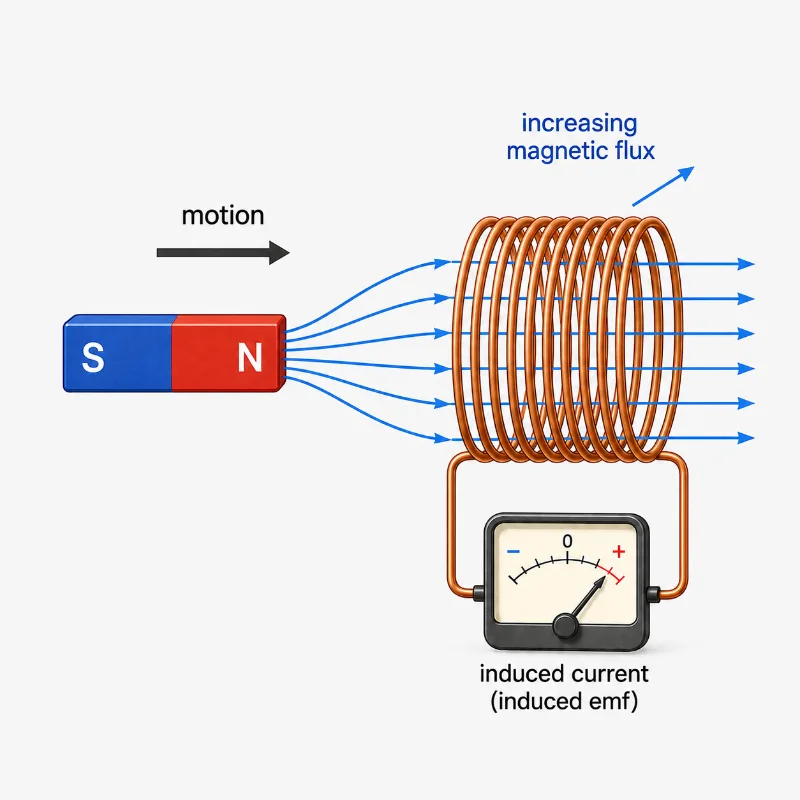
This illustration introduces Faraday’s law by showing a magnet moving toward a coil. As the magnetic field linked with the coil changes, magnetic flux increases and an induced emf is detected by the meter. The picture helps students see that induction is caused by changing flux, not simply by the presence of a magnetic field.
Electromagnetic Induction Learning Pathway
This page begins the Electromagnetic Induction cluster by focusing on magnetic flux and Faraday’s law. The later pages build on this foundation by explaining the direction of induced current, the role of energy conservation, inductance in coils, and the operation of generators, motors, and transformers.
Electricity and Magnetism
Provides the wider physics context for electric fields, circuits, magnetic fields, induction, electromagnetic waves, and electrical technologies.Electromagnetic Induction
Introduces how changing magnetic fields and changing currents can produce induced emf, induced current, and practical energy conversion.Magnetic Flux and Faraday’s Law
Explains how magnetic flux is defined and why changing magnetic flux produces induced emf in a coil or circuit.Lenz’s Law and Energy Conservation
Shows how the direction of induced current is determined and why induction must obey energy conservation.Self-Inductance and Mutual Inductance
Explains how changing current can induce voltage in the same coil or in a neighbouring coil.Generators, Motors, and Transformers
Connects electromagnetic induction to machines that generate electricity, produce motion, and transform voltage.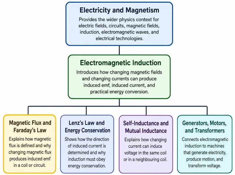
The diagram presents a 1-1-4 learning pathway for the Electromagnetic Induction cluster. It begins with Electricity and Magnetism as the wider physics context, then narrows to Electromagnetic Induction as the cluster overview. From there, it branches into four related pages: Magnetic Flux and Faraday’s Law, Lenz’s Law and Energy Conservation, Self-Inductance and Mutual Inductance, and Generators, Motors, and Transformers. The highlighted Magnetic Flux and Faraday’s Law branch indicates the first terminal page in the sequence, helping students see how the idea of changing magnetic flux provides the foundation for later topics in electromagnetic induction.
The Core Physical Idea
The core idea is simple but powerful: a changing magnetic flux through a circuit induces an emf. This means that a circuit can experience a voltage when the magnetic field linked with it changes.
Magnetic flux is represented by \( \Phi \). For a uniform magnetic field passing through a flat area, magnetic flux is:
\( \Phi = BA\cos\theta \)
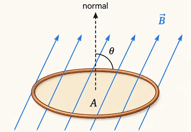
where \( \Phi \) is magnetic flux, \( B \) is magnetic field strength, \( A \) is the area of the loop or surface, and \( \theta \) is the angle between the magnetic field and the normal to the surface.
The normal is an imaginary line drawn perpendicular to the surface. This is important because the angle in the equation is not usually measured between the magnetic field and the surface itself, but between the magnetic field and the normal to the surface.
Faraday’s law then connects changing flux to induced emf:
\( \varepsilon = -N\frac{\Delta\Phi}{\Delta t} \)
where \( \varepsilon \) is the induced emf, \( N \) is the number of turns in the coil, \( \Delta\Phi \) is the change in magnetic flux through one turn, and \( \Delta t \) is the time taken for that change.
The larger the change in magnetic flux, the greater the induced emf. The faster the change occurs, the greater the induced emf. A coil with more turns also produces a larger induced emf because the flux change is linked through more loops of wire.
Visual Guide to Magnetic Flux and Faraday’s Law
The following illustrations show how magnetic flux depends on area and orientation, how moving magnets and rotating coils change flux, and why these changes can induce emf. They are placed here to help students build visual intuition before moving into applications and problem solving.
Pictorial Illustration 1: Magnetic Flux Through a Loop
Pictorial Illustration 2: Changing Magnetic Flux by Moving a Magnet
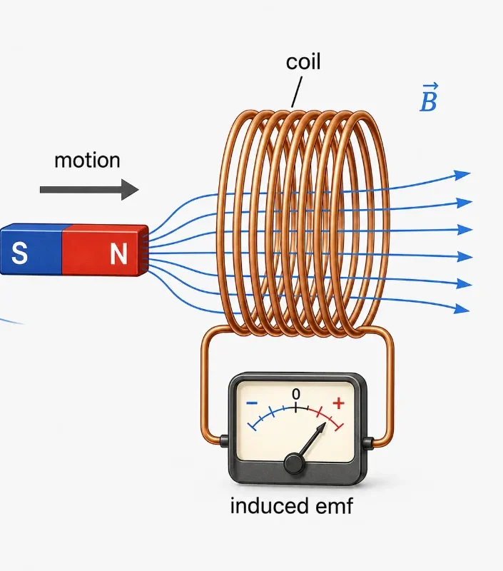
This illustration shows a bar magnet moving relative to a coil. As the magnet approaches or moves away, the magnetic field linked with the coil changes, so the magnetic flux through the coil changes. The diagram reinforces the central idea that induction depends on changing flux, not merely on placing a magnet near a conductor.
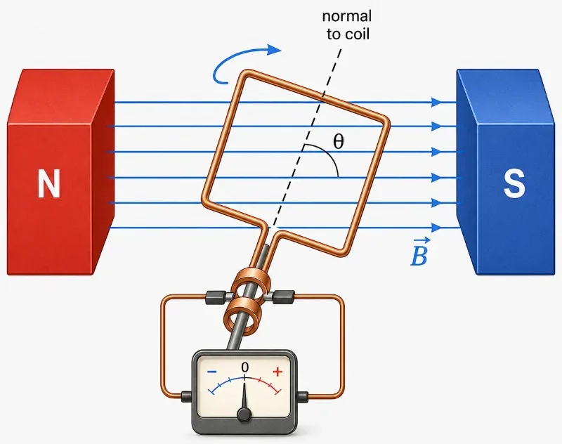
Pictorial Illustration 3: Rotating Coil in a Magnetic Field
What Magnetic Flux Measures
Magnetic flux is often described as the amount of magnetic field passing through a surface. This is a useful beginner’s picture, but it should be understood carefully. Magnetic flux is not a substance flowing through the loop. It is a calculated quantity that combines field strength, area, and direction.
If the magnetic field is stronger, more flux passes through the same area. If the loop is larger, more field lines may pass through it. If the loop is tilted, less of the field passes through it effectively. These three features are gathered into the expression \( \Phi = BA\cos\theta \).
Magnetic Field Strength \( B \)
A stronger magnetic field increases magnetic flux if area and angle remain unchanged.Area \( A \)
A larger loop or surface can link more magnetic field and therefore produce greater magnetic flux.Angle \( \theta \)
The angle determines how directly the magnetic field passes through the surface. The maximum flux occurs when the field is parallel to the surface normal.Flux Unit
Magnetic flux is measured in weber, symbol \( \text{Wb} \). Since \( \Phi = BA \), one weber is equivalent to one tesla square metre.When Magnetic Flux Is Maximum, Zero, or Negative
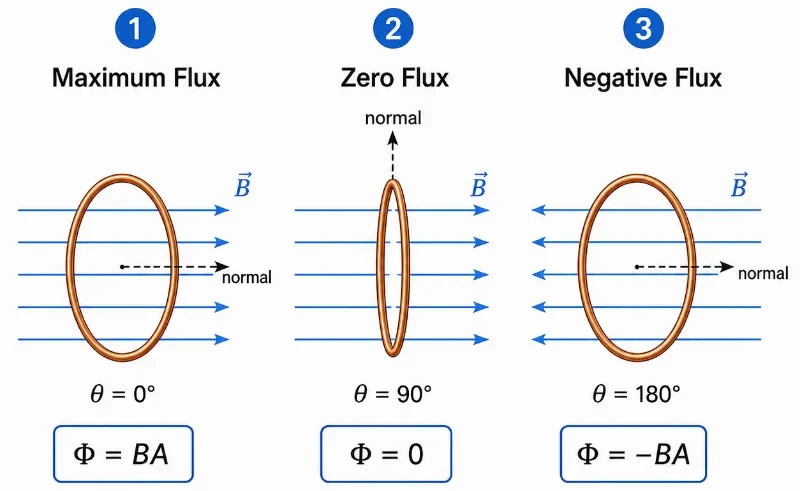
The equation \( \Phi = BA\cos\theta \) tells us how orientation affects magnetic flux. If the magnetic field is parallel to the normal of the surface, \( \theta = 0^\circ \), so \( \cos\theta = 1 \). The flux is maximum.
If the magnetic field is parallel to the surface itself, \( \theta = 90^\circ \), so \( \cos\theta = 0 \). The flux is zero because the field does not pass through the surface in the normal direction.
If the magnetic field points opposite to the chosen normal direction, the flux can be negative. This does not mean the magnetic field is weak or unreal. It means the field passes through the surface in the opposite orientation to the chosen positive direction.
Pictorial Illustration 4: Maximum, Zero, and Negative Flux
How Magnetic Flux Can Change
Faraday’s law depends on changing magnetic flux. There are several ways this change can happen. Understanding these methods helps students see why electromagnetic induction appears in many different devices.
Changing the Magnetic Field Strength
If the magnetic field through a coil becomes stronger or weaker, the magnetic flux changes, so emf may be induced.Changing the Area of the Loop
If the area exposed to the magnetic field changes, the flux changes. This can happen when a sliding conductor changes the size of a circuit loop.Changing the Angle
A rotating coil changes the angle between the magnetic field and the normal to the loop, causing the flux to vary.Changing the Number of Turns
A coil with more turns links the changing flux many times, increasing the total induced emf.Moving the Coil or Magnet
Relative motion between a magnet and a coil can change the amount of magnetic field passing through the coil.Faraday’s Law in Words
Faraday’s law says that the induced emf in a circuit is proportional to the rate of change of magnetic flux linkage through the circuit.
The phrase “rate of change” is very important. A slow change in magnetic flux produces a smaller induced emf. A rapid change produces a larger induced emf. This is why quickly moving a magnet in and out of a coil can produce a larger meter deflection than moving it slowly.
For a coil with \( N \) turns:
\( \varepsilon = -N\frac{\Delta\Phi}{\Delta t} \)
The expression \( N\Phi \) is sometimes called flux linkage. A coil with many turns has more flux linkage than a single loop, so the induced emf is larger for the same change in flux per turn.
What the Negative Sign Means
The negative sign in Faraday’s law points toward Lenz’s law. It tells us that the induced emf has a direction such that the induced current opposes the change in magnetic flux that produced it.
This direction is not a small detail. It is what prevents electromagnetic induction from creating energy for free. If induced currents helped the change that produced them, a system could reinforce itself without limit. Instead, induced currents oppose the change, so external work or energy input is required.
In this page, the main focus is the magnitude of induced emf and the meaning of changing flux. The next page on Lenz’s law will focus more deeply on direction and energy conservation.
Induced EMF and Induced Current
Induced emf and induced current are related, but they are not identical. Induced emf is the voltage produced by changing magnetic flux. Induced current flows only if there is a complete conducting path.
For example, moving a magnet into a closed coil can induce a current because charges have a complete path around the circuit. If the coil is open, an emf may still be induced between the ends of the coil, but a continuous current cannot flow around the broken circuit.
Induced EMF
The voltage effect produced by changing magnetic flux. It can exist even if the circuit is not closed.Induced Current
The current that flows when induced emf acts in a complete conducting path.Closed Circuit
A complete circuit allows induced current to flow when emf is induced.Open Circuit
An open circuit may have induced emf, but it does not allow continuous induced current.The One Idea to Remember
Faraday’s law says that changing magnetic flux induces emf.
This is the heart of electromagnetic induction. A magnetic field by itself is not enough. A coil by itself is not enough. What matters is changing magnetic flux linked with a circuit.
Key Equations for Magnetic Flux and Faraday’s Law
The magnetic flux through a flat surface in a uniform magnetic field is:
\( \Phi = BA\cos\theta \)
\( \Phi \) — Magnetic flux, measured in webers. It describes the effective magnetic field passing through a surface.
\( B \) — Magnetic field strength, measured in tesla. A stronger field can produce greater flux.
\( A \) — Area of the surface or loop. A larger area can link more magnetic field.
\( \theta \) — The angle between the magnetic field and the normal to the surface.
Faraday’s law for a coil is:
\( \varepsilon = -N\frac{\Delta\Phi}{\Delta t} \)
\( \varepsilon \) — Induced emf, measured in volts. It is the voltage produced by changing magnetic flux.
\( N \) — Number of turns in the coil. More turns usually produce a larger induced emf.
\( \Delta\Phi \) — Change in magnetic flux through one turn of the coil.
\( \Delta t \) — Time taken for the flux change. A shorter time gives a larger rate of change and therefore a larger induced emf.
Advanced Field Mapping: Integrating Flux Over Non-Uniform Fields
The baseline expression \(\Phi = BA\cos\theta\) is an excellent tool when the ambient magnetic field vector is perfectly uniform across the entire surface boundary. However, in real-world engineering and university physics, magnetic fields often vary in intensity and direction from one coordinate to the next. To calculate flux accurately under non-uniform conditions, we must slice the surface into infinitesimal area patches (\(d\mathbf{A}\)) and evaluate a formal surface integral:
$$ \Phi_B = \int_S \mathbf{B} \cdot d\mathbf{A} $$Consider a classic university scenario: a flat rectangular loop of width \(w\) and length \(L\) is positioned a distance \(x\) away from a long straight wire carrying a current \(I\). The magnetic field produced by the straight wire drops off inversely with distance (\(B(r) = \frac{\mu_0 I}{2\pi r}\)). Because the field changes continuously across the width of the loop, we define a differential strip area \(d\mathbf{A} = L \, dr\) and integrate from the inner edge to the outer edge:
$$ \Phi_B = \int_x^{x+w} \left( \frac{\mu_0 I}{2\pi r} \right) L \, dr = \frac{\mu_0 I L}{2\pi} \int_x^{x+w} \frac{1}{r} \, dr $$$$ \Phi_B = \frac{\mu_0 I L}{2\pi} \ln\left(\frac{x+w}{x}\right) $$This integration calculus bridge teaches students to view magnetic flux as a continuous geometric accumulation across vector space, a mindset crucial for mastering high-level electromagnetic design.
Advanced Treatment: The Total Time-Derivative Expansion
In basic problems, we typically alter only one system parameter at a time—either changing the field strength or rotating the coil. For advanced electrodynamics, Faraday’s Law must be evaluated using a comprehensive total time derivative to track systems where field strength, loop area boundaries, and spatial orientations change simultaneously:
$$ \varepsilon(t) = -N \frac{d}{dt} \left[ \int_S \mathbf{B}(t) \cdot d\mathbf{A}(t) \right] $$By applying the multi-variable calculus chain rule to the product of our fundamental variables, we can expand the instantaneous rate of flux change into distinct, independent components:
$$ \frac{d\Phi_B}{dt} = \left(\frac{\partial B}{\partial t}\right)A\cos\theta + B\left(\frac{\partial A}{\partial t}\right)\cos\theta – BA\sin\theta\left(\frac{\partial \theta}{\partial t}\right) $$When substituted back into Faraday’s expression, each mathematical term maps to a specific physical mechanism:
- The Transformer Term \(\left(\frac{\partial B}{\partial t}\right)\): Tracks the induced voltage caused strictly by time-varying field oscillations, matching the physics utilized inside stationary power transformers.
- The Boundary Deforming Term \(\left(\frac{\partial A}{\partial t}\right)\): Tracks voltage shifts caused by physically expanding, contracting, or squeezing the circuit loop geometry inside the field.
- The Rotational Motional Term \(\left(\frac{\partial \theta}{\partial t}\right)\): Tracks the sinusoidal potential waves generated strictly by rotating the coil angular velocity relative to the field lines, forming the operational foundation of mechanical AC generators.
From Formula to Meaning
The equation \( \Phi = BA\cos\theta \) helps us identify what can change. If \( B \), \( A \), or \( \theta \) changes, then \( \Phi \) changes. If \( \Phi \) changes with time, Faraday’s law tells us that emf is induced.
This means Faraday’s law is not just about magnets moving near coils. It is about changing field relationships. A magnetic field can change in strength, a loop can rotate, a circuit area can expand or shrink, or a coil can move into a stronger or weaker field region.
The formula also explains why generators are designed with coils, strong magnetic fields, and rapid rotation. More turns, stronger fields, larger areas, and faster changes can all increase the induced emf.
Worked Example
Problem: A coil has \( 80 \) turns. The magnetic flux through each turn changes from \( 0.030 \ \text{Wb} \) to \( 0.010 \ \text{Wb} \) in \( 0.20 \ \text{s} \). Find the magnitude of the induced emf.
Given: \( N = 80 \), initial flux \( \Phi_i = 0.030 \ \text{Wb} \), final flux \( \Phi_f = 0.010 \ \text{Wb} \), and \( \Delta t = 0.20 \ \text{s} \).
Method: Use the magnitude form of Faraday’s law:
\( |\varepsilon| = N\frac{|\Delta\Phi|}{\Delta t} \)
Solution:
\( \Delta\Phi = \Phi_f – \Phi_i \)
\( \Delta\Phi = 0.010 – 0.030 \)
\( \Delta\Phi = -0.020 \ \text{Wb} \)
For magnitude, use \( |\Delta\Phi| = 0.020 \ \text{Wb} \).
\( |\varepsilon| = 80\frac{0.020}{0.20} \)
\( |\varepsilon| = 80(0.10) \)
\( |\varepsilon| = 8.0 \ \text{V} \)
Interpretation: The induced emf has a magnitude of \( 8.0 \ \text{V} \). The flux is decreasing, and the negative sign in Faraday’s law would help determine the direction of the induced emf using Lenz’s law.
Worked Example Illustration
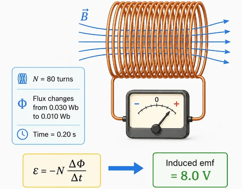
This worked-example illustration connects the numerical data to the physical setup. A coil with 80 turns experiences a magnetic flux change from \( 0.030 \ \text{Wb} \) to \( 0.010 \ \text{Wb} \) in \( 0.20 \ \text{s} \), producing an induced emf of \( 8.0 \ \text{V} \). The diagram helps students see how Faraday’s law links flux change, time, coil turns, and induced voltage.
What Students Usually Get Wrong
Students often find Faraday’s law confusing because it combines geometry, change, and circuit behaviour. The formula looks short, but it contains several ideas that must be separated carefully.
Thinking a Magnetic Field Alone Causes Induction
A steady magnetic field does not automatically induce emf. The magnetic flux must change with time.Confusing Magnetic Field with Magnetic Flux
Magnetic field strength \( B \) is only one part of magnetic flux. Flux also depends on area and angle.Using the Wrong Angle
In \( \Phi = BA\cos\theta \), the angle is between the magnetic field and the normal to the surface, not necessarily the surface itself.Ignoring the Number of Turns
A coil with many turns links the changing flux many times, increasing the induced emf.Forgetting That Induced Current Needs a Closed Circuit
Induced emf may exist in an open circuit, but continuous induced current requires a complete path.Treating the Negative Sign as Ordinary Arithmetic Only
The negative sign in Faraday’s law has physical meaning. It points to the direction of induction described by Lenz’s law.Where This Appears in Real Life
Faraday’s law is not just an examination formula. It is the operating principle behind many technologies that convert mechanical motion, changing current, or changing magnetic fields into useful electrical effects.
Electric Generators
Generators use changing magnetic flux to produce emf. Mechanical rotation from turbines, engines, wind, or water can be converted into electrical energy.Transformers
Transformers depend on changing magnetic flux linking two coils. This allows voltage to be stepped up or stepped down in AC power systems.Induction Cooktops
Changing magnetic fields induce currents in suitable cookware, producing heating directly in the metal.Wireless Charging
Changing current in one coil creates changing magnetic flux that can induce voltage in another nearby coil.Electric Guitar Pickups
Vibrating metal strings disturb magnetic flux near a coil, inducing a small electrical signal that can be amplified.Magnetic Sensors
Many sensors detect motion, rotation, or changing magnetic fields by measuring induced voltage.Real-World Illustration
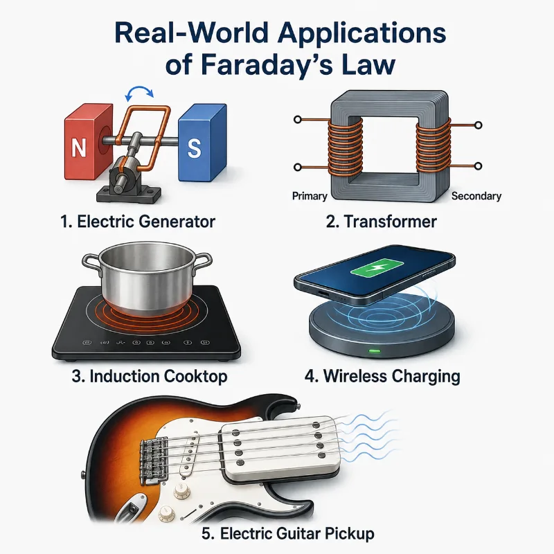
This illustration connects Faraday’s law to familiar technologies. In each example, a changing magnetic field, moving conductor, or changing current changes the magnetic flux linked with a circuit. The induced emf can then be used to generate electricity, transfer energy, detect motion, heat cookware, charge devices, or produce an audio signal.
Bridge to University Thinking
At university level, Faraday’s law becomes more than a coil-and-magnet rule. It becomes one of Maxwell’s equations, showing that a changing magnetic field is linked to a circulating electric field.
This deeper view explains why electromagnetic induction can occur even when there is no battery pushing charges around a circuit. The changing magnetic field is associated with an induced electric field, and that electric field can drive charges in a conductor.
For engineering students, Faraday’s law becomes essential in electrical machines, power transformers, motors, sensors, wireless power, power electronics, electromagnetic compatibility, and communication systems. A simple school-level law becomes a design principle for real systems.
Quick Interactive Check
Check Your Understanding of Magnetic Flux and Faraday’s Law
Use these short questions to test whether you understand electromagnetic induction as changing magnetic flux producing induced emf.
What must happen for an emf to be induced in a coil?
Your thinking prompt: Think about whether a steady magnetic field is enough.
Suggested answer: The magnetic flux through the coil must change with time. A steady magnetic flux does not induce emf.
What three quantities determine magnetic flux in \( \Phi = BA\cos\theta \)?
Your thinking prompt: Look at the symbols in the equation and what each one represents.
Suggested answer: Magnetic flux depends on magnetic field strength, area, and the angle between the magnetic field and the normal to the surface.
Why does moving a magnet faster through a coil produce a larger induced emf?
Your thinking prompt: Think about the rate of change of magnetic flux.
Suggested answer: Moving the magnet faster changes the magnetic flux in a shorter time, increasing \( \frac{\Delta\Phi}{\Delta t} \), so the induced emf becomes larger.
What happens to induced emf if the number of turns in a coil is doubled, assuming the same flux change per turn and the same time interval?
Your thinking prompt: Look at the factor \( N \) in Faraday’s law.
Suggested answer: The induced emf doubles because \( \varepsilon \) is proportional to the number of turns \( N \).
Can an emf be induced if a circuit is open?
Your thinking prompt: Separate induced emf from induced current.
Suggested answer: Yes. An emf can be induced in an open circuit, but continuous induced current requires a closed conducting path.
Key takeaway: Faraday’s law says that changing magnetic flux induces emf. The faster the flux changes and the more coil turns are linked, the larger the induced emf.
Review Questions and Answers
- What is magnetic flux?Answer: Magnetic flux is a measure of the effective magnetic field passing through a surface. It depends on magnetic field strength, area, and angle.
- What is the formula for magnetic flux through a flat surface in a uniform magnetic field?Answer: \( \Phi = BA\cos\theta \), where \( \theta \) is the angle between the magnetic field and the normal to the surface.
- What is Faraday’s law in words?Answer: Faraday’s law states that an emf is induced when the magnetic flux linked with a circuit changes with time.
- Why does a coil with more turns produce a larger induced emf?Answer: More turns increase the total flux linkage, so the same change in flux per turn produces a larger total induced emf.
- What is the difference between induced emf and induced current?Answer: Induced emf is the voltage produced by changing magnetic flux. Induced current flows only if there is a complete conducting path.
- Why does rotating a coil in a magnetic field induce emf?Answer: Rotation changes the angle between the magnetic field and the normal to the coil, causing the magnetic flux to change.
- What does the negative sign in Faraday’s law indicate?Answer: It indicates the direction of the induced emf, which is related to Lenz’s law. The induced effect opposes the change that produces it.
- What is the unit of magnetic flux?Answer: The unit of magnetic flux is the weber, symbol \( \text{Wb} \).
Thought-Provoking Questions and Answers
- Why is change more important than presence in Faraday’s law?Suggested answer: A magnetic field can be present without inducing emf. Induction occurs only when the magnetic flux linked with a circuit changes. This shows that electromagnetic induction is about dynamic relationships, not just static fields.
- Why does Faraday’s law make generators possible?Suggested answer: Generators are designed to change magnetic flux through coils. This changing flux induces emf, allowing mechanical motion to be converted into electrical energy.
- Why is magnetic flux a better idea than simply counting magnetic field strength?Suggested answer: Magnetic field strength alone does not tell us how much field passes through a circuit. Flux includes field strength, area, and orientation, which are all important in induction.
- Why does Faraday’s law prepare students for modern electrical engineering?Suggested answer: Faraday’s law appears in generators, motors, transformers, sensors, wireless charging, and power systems. It teaches how fields and circuits exchange energy.
- Why is the negative sign in Faraday’s law physically meaningful?Suggested answer: The negative sign shows that induced effects have a direction that opposes the change in flux. This is connected to energy conservation and is explored more deeply through Lenz’s law.
Numerical Problems and Solutions
- A rectangular loop of area \( 0.040 \ \text{m}^2 \) is placed perpendicular to a magnetic field of \( 0.50 \ \text{T} \). Find the magnetic flux through the loop.Solution:Since the field is perpendicular to the surface, it is parallel to the normal, so \( \theta = 0^\circ \).\( \Phi = BA\cos\theta \)\( \Phi = (0.50)(0.040)\cos 0^\circ \)\( \Phi = 0.020 \ \text{Wb} \)Answer: The magnetic flux is \( 0.020 \ \text{Wb} \).
- A coil of \( 60 \) turns has a flux change of \( 0.015 \ \text{Wb} \) per turn in \( 0.10 \ \text{s} \). Find the magnitude of the induced emf.Solution:\( |\varepsilon| = N\frac{|\Delta\Phi|}{\Delta t} \)\( |\varepsilon| = 60\frac{0.015}{0.10} \)\( |\varepsilon| = 60(0.15) \)\( |\varepsilon| = 9.0 \ \text{V} \)Answer: The induced emf is \( 9.0 \ \text{V} \).
- A circular loop has area \( 0.020 \ \text{m}^2 \). It is placed in a magnetic field of \( 0.80 \ \text{T} \), with the field making an angle of \( 60^\circ \) with the normal to the loop. Find the magnetic flux.Solution:\( \Phi = BA\cos\theta \)\( \Phi = (0.80)(0.020)\cos 60^\circ \)\( \Phi = (0.016)(0.5) \)\( \Phi = 0.0080 \ \text{Wb} \)Answer: The magnetic flux is \( 0.0080 \ \text{Wb} \).
- A \( 120 \)-turn coil experiences an induced emf of \( 24 \ \text{V} \) when the flux through each turn changes uniformly in \( 0.40 \ \text{s} \). Find the magnitude of the flux change per turn.Solution:\( |\varepsilon| = N\frac{|\Delta\Phi|}{\Delta t} \)Rearrange:\( |\Delta\Phi| = \frac{|\varepsilon|\Delta t}{N} \)\( |\Delta\Phi| = \frac{(24)(0.40)}{120} \)\( |\Delta\Phi| = \frac{9.6}{120} \)\( |\Delta\Phi| = 0.080 \ \text{Wb} \)Answer: The flux change per turn is \( 0.080 \ \text{Wb} \).
Summary
Magnetic flux measures the effective magnetic field passing through a surface. It depends on magnetic field strength, area, and angle. The equation \( \Phi = BA\cos\theta \) captures these relationships in a simple form.
Faraday’s law states that an induced emf is produced when magnetic flux linked with a circuit changes with time. For a coil, the induced emf depends on the number of turns and the rate of change of flux: \( \varepsilon = -N\frac{\Delta\Phi}{\Delta t} \).
This principle explains the operation of generators, transformers, induction cooktops, wireless chargers, sensors, and many electrical systems. It is one of the central bridges between magnetic fields and usable electrical energy.
Final takeaway: Faraday’s law turns changing magnetic flux into induced emf, allowing motion and changing fields to become electrical effects.
Glossary
- Magnetic Flux
- The effective amount of magnetic field passing through a surface, represented by \( \Phi \).
- Faraday’s Law
- The law stating that changing magnetic flux through a circuit induces an emf.
- Electromagnetic Induction
- The process by which changing magnetic flux produces induced emf and, in a closed circuit, induced current.
- Induced EMF
- The voltage produced by changing magnetic flux through a circuit or coil.
- Induced Current
- The current that flows when induced emf acts in a complete conducting path.
- Flux Linkage
- The total magnetic flux linked with all turns of a coil, often represented by \( N\Phi \).
- Weber
- The SI unit of magnetic flux, symbol \( \text{Wb} \).
- Tesla
- The SI unit of magnetic field strength, symbol \( \text{T} \).
- Surface Normal
- An imaginary line perpendicular to a surface, used to define the angle in magnetic flux calculations.
- Lenz’s Law
- The rule that gives the direction of induced emf or current, stating that the induced effect opposes the change that produces it.
Frequently Asked Questions
What is magnetic flux in simple terms?
Magnetic flux describes how much magnetic field effectively passes through a surface. It depends on field strength, area, and angle.
What does Faraday’s law explain?
Faraday’s law explains how changing magnetic flux through a circuit induces an emf.
Does a steady magnetic field induce emf?
No. A steady magnetic field does not induce emf unless the magnetic flux through the circuit changes.
Why does moving a magnet near a coil induce voltage?
Moving the magnet changes the magnetic flux through the coil. This changing flux induces an emf according to Faraday’s law.
Why does a coil with more turns produce greater induced emf?
More turns increase the total flux linkage, so the induced emf is larger for the same change in magnetic flux per turn.
External References
- OpenStax University Physics: Faraday’s Law — A clear university-level introduction to magnetic flux and induced emf.
- PhET: Faraday’s Law Simulation — An interactive simulation for exploring how changing magnetic flux can produce electricity.
- MIT OpenCourseWare: Electromagnetic Induction — A deeper treatment of Faraday’s law in electromagnetic field theory.