
Capacitance is the fundamental geometric and material capability of a physical system to store separated electric charge under an applied potential difference. While introductory frameworks often define a capacitor as a simple mechanical charge container, advanced field theory reveals a deeper physical reality: it is a structured system designed to establish a localized vector field and store electrostatic potential energy within the field configuration between separated charge boundaries.
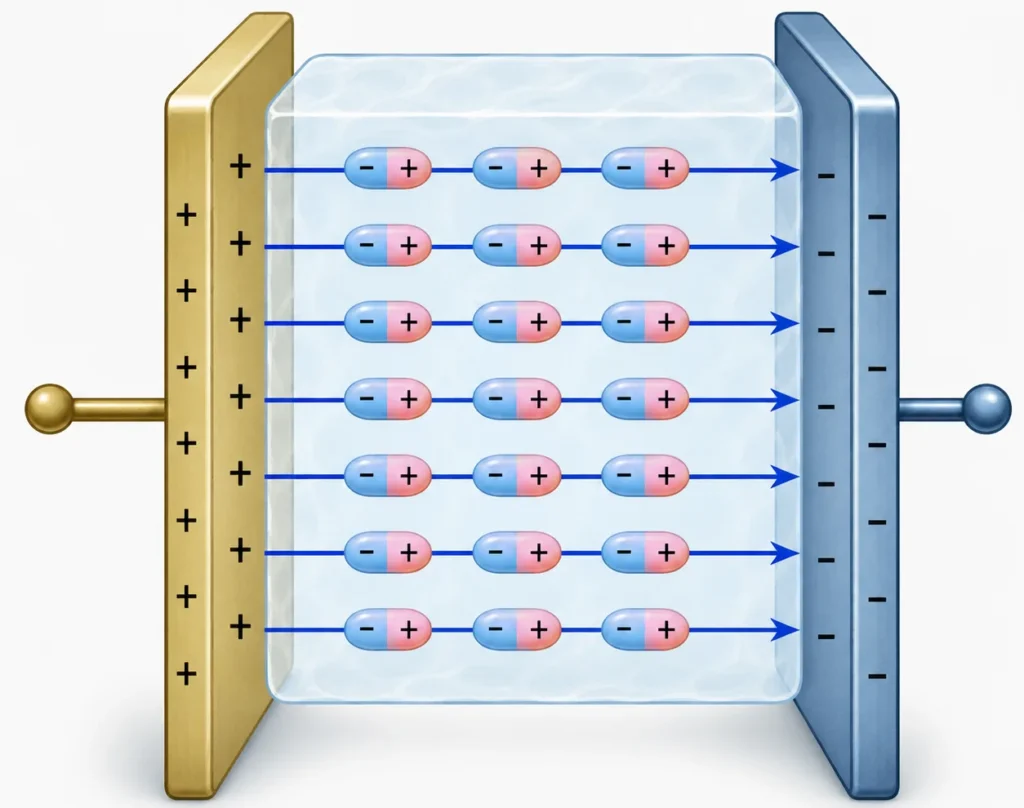
Introducing dielectric media adds significant academic depth to this system. A dielectric is an insulating, non-conducting material possessing a high electrical permittivity. When placed within an external electric field, it restricts the macroscopic migration of free current carriers but undergoes microscopic atomic or molecular polarization. This localized realignment establishes an internal induced field that counteracts the external field, altering the net electrical displacement and allowing the system to hold a significantly higher charge density at the exact same operating voltage.
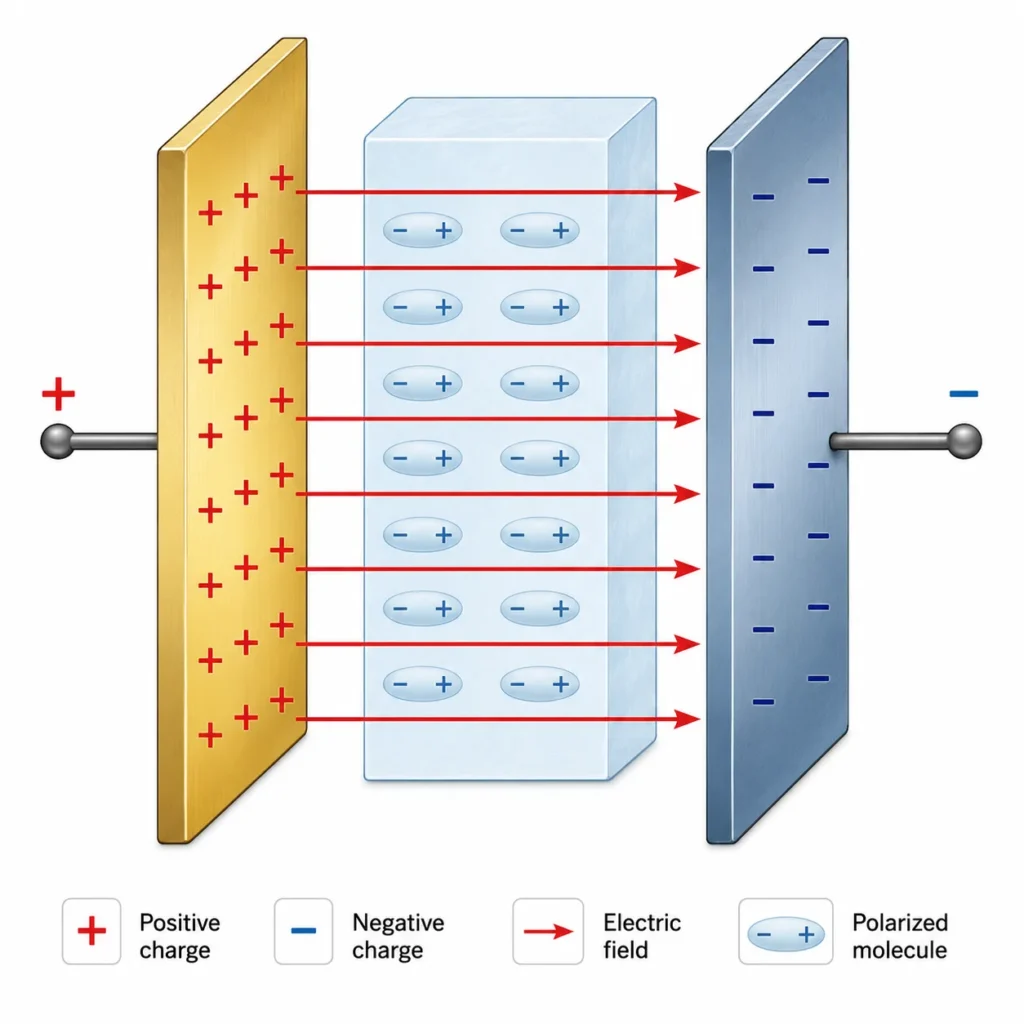
The technical schematic above highlights a classic parallel-plate capacitor configuration operating with equal and opposite surface charge distributions. The resultant electric field vectors span the gap uniformly. When the dielectric material is inserted, its internal molecular dipoles actively align parallel to the field lines. This visualization shifts the student’s focus away from simple surface charge mechanics toward continuous field energy storage: the separated charge bounds act as a source that modifies the physical state of space, storing energy directly within the localized volumetric field lines.
Learning Pathway in Electrostatics
Electrostatics Overview
Provides the global parent context for understanding charges at rest, Coulomb interactions, vector fields, scalar potentials, macroscopic capacitance, and volumetric energy density.
Electric Charge and Coulomb’s Law
Establishes the foundational pathway by quantifying electrostatic force behaviors, point-charge attraction or repulsion dynamics, and basic inverse-square distance relationships.
Electric Fields and Field Lines
Maps spatial vector influence, demonstrating how stationary charge arrays alter surrounding space and how field line densities represent field strength magnitudes.
Electric Potential and Voltage
Transitions system models from vector forces to conservative scalar energy states, defining voltage as potential energy change per unit charge.
Capacitance and Dielectrics
Applies vector field integrations and scalar potential values to physical hardware design, material polarization properties, and volumetric field energy retention.
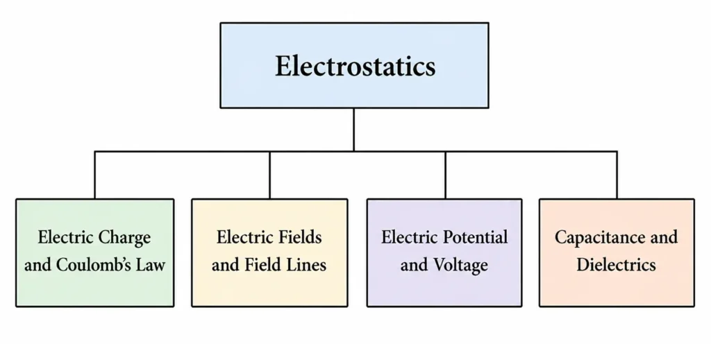
This structure chart shows the four main learning pages within the Electrostatics section. Capacitance and Dielectrics appears alongside Electric Charge and Coulomb’s Law, Electric Fields and Field Lines, and Electric Potential and Voltage. The chart helps students see how capacitance builds on earlier ideas: charges create forces, fields describe electric influence in space, voltage describes energy per unit charge, and capacitors use these ideas to store charge and energy in electric fields.
The Core Physical Idea
Parallel-Plate Capacitor Structure
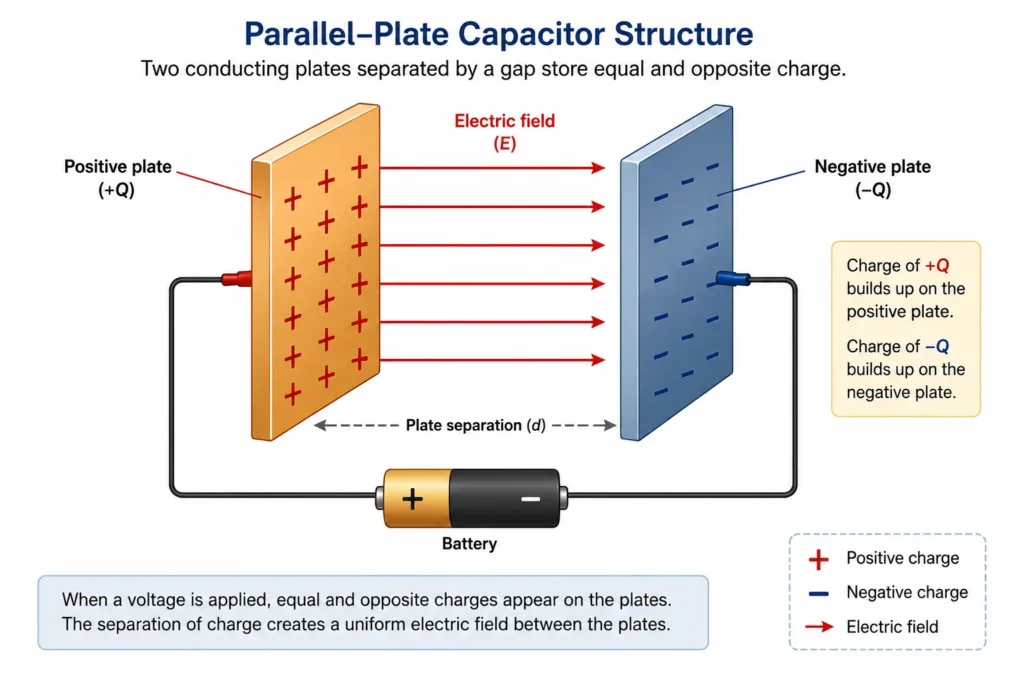
This illustration shows the basic structure of a parallel-plate capacitor. A battery separates charge by placing positive charge on one plate and negative charge on the other. The two plates do not touch, but the separated charges create a nearly uniform electric field in the gap between them. The diagram helps students see that a capacitor is not simply a pair of metal plates; it is a physical system where voltage produces charge separation and stores energy in the electric field.
How Geometry Affects Capacitance
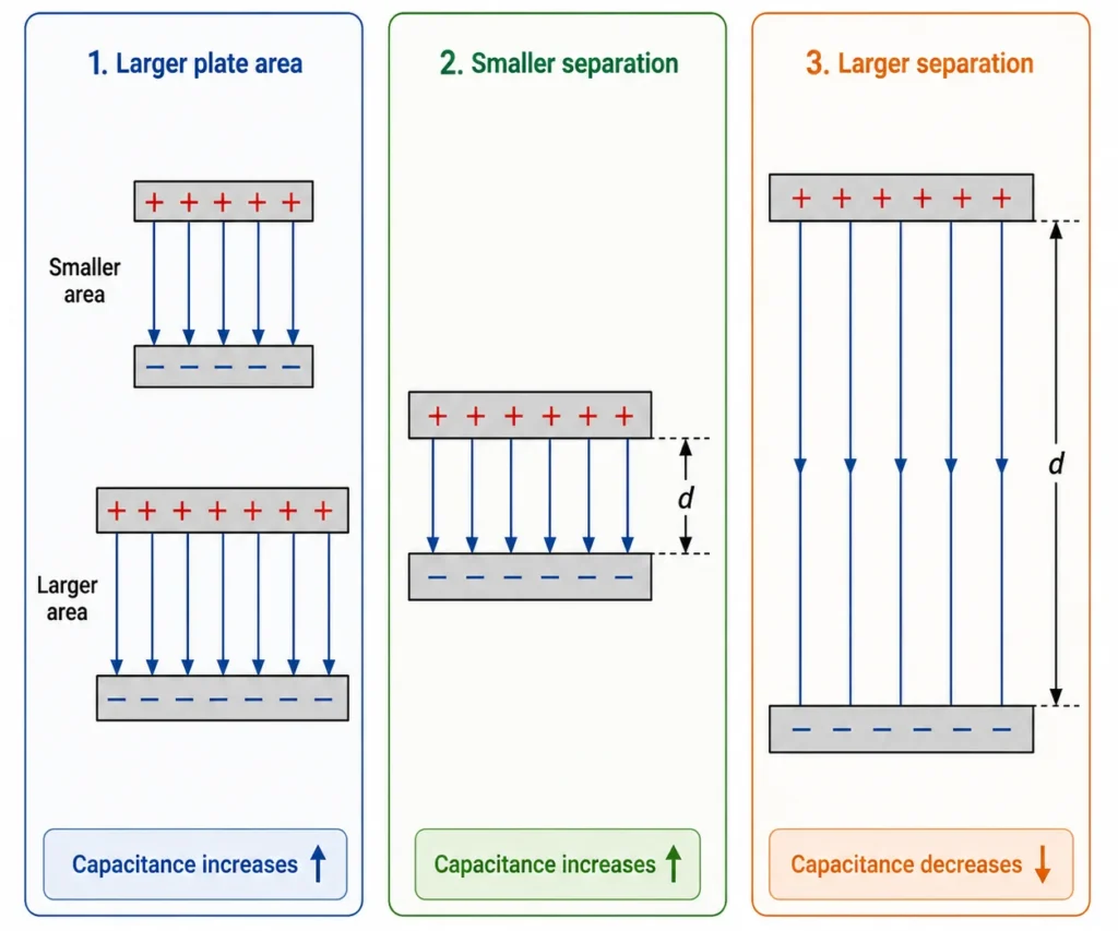
This multi-panel geometric visualization demonstrates the direct proportionality relationships dictating structural capacitance. Panel A and B emphasize that scaling the physical plate surface area provides a wider distribution space for incoming charge arrays, effectively maximizing electrical capacity. Decreasing the intervening spatial gap amplifies the cross-boundary Coulomb attractions, reinforcing the field’s structural stability. Panel C illustrates that increasing the boundary separation weakens these cross-gap field lines, lowering the overall capacity of the system.
Dielectric Polarisation Under Field Constraints
The Primary Pillar to Remember
A capacitor stores potential energy within a localized space by separating charge arrays and maintaining a continuous electric field between boundary conductors.
Visualizing the Physical System
Isolate Separated Charge Arrays
Visualize positive and negative electron distributions held in permanent suspension. They are driven by intense cross-gap mutual attractions but are blocked from recombining by the insulating boundary layer.
Map Volumetric Field Storage
Focus your attention on the open spatial volume between the conductors. This localized field matrix is the actual physical region where the system’s potential energy resides.
Analyze Voltage As Field Strain
Voltage acts as the electrical pressure driving charge separation. Increasing this scalar difference amplifies the density of the vector field lines running across the gap.
Track Dielectric Shielding
Picture the internal molecules of the insulator shifting their atomic centers. This microscopic dipole alignment creates an internal reverse field that safely buffers the primary field strain.
Key Equations and Physical Interpretations
Physical Meaning of C = Q / V
Capacitance establishes the exact linear scaling factor between charge accumulation and voltage drop. It tracks the specific amount of coulombs stored per individual volt.
Geometric Influence of Area (A)
Expanding the surface area provides more space for charge arrays to distribute, lowering localized mutual repulsions and directly increasing capacity.
Geometric Influence of Gap Distance (d)
Bringing the plates closer intensifies the binding electrostatic forces across the gap, maximizing charge retention and causing capacitance to skyrocket.
The Scaling Factor of the Dielectric Constant (κ)
The dimensionless value κ tracks the material’s exact polarization capacity. It acts as a direct multiplier for the baseline electrical permittivity of a vacuum.
From Formula to Meaning
Advanced Mathematical Rigor: Continuous Field Integrals
Worked Analytical Example
- Net Charge magnitude (Q) = 6.0 × 10⁻⁶ C
- Potential Difference (V) = 12 V
Common Conceptual Misconceptions
The Dielectric Leakage Myth
Misconception: A dielectric increases capacitance by letting a small current pass across the gap.
Reality: A dielectric is a robust insulator. If free electrons flow across it, the system undergoes dielectric breakdown, short-circuiting and destroying the capacitor.
Internal Charge Location Error
Misconception: Free net charge is stored directly inside the core volume of the dielectric material.
Reality: Free net charge resides exclusively on the surface layers of the conducting plates. The dielectric contains only bound charges that polarize in place.
Variable Capacitance Fallacy
Misconception: Changing the applied voltage or net charge alters the core capacitance value.
Reality: Capacitance is a geometric and material constant. Altering Q or V scales the other parameter proportionally, keeping the ratio C = Q / V fixed.
The Empty Container Paradigm
Misconception: A capacitor is a passive, empty tank that holds electric charge like water.
Reality: A capacitor is an active vector field energy reservoir. It works by maintaining structural field tension and storing energy within the field lines spanning the gap.
Real-World Engineering Frameworks
Transient High-Power Modules
Systems like medical defibrillators and high-intensity camera flashes draw energy slowly from a power source, store it in the electric field, and release it near-instantaneously to output massive currents that batteries cannot match.
Power Supply Filtering Circuits
Capacitors act as localized electrical reservoirs in AC-to-DC converters, absorbing voltage spikes and discharging energy during drops to provide a clean, steady direct current to sensitive microchips.
Capacitive Sensing Arrays
Modern touch interfaces use grids of micro-capacitors to track touch inputs. Introducing a finger—which has a different permittivity than air—disrupts the local field, altering the capacitance at specific coordinates to map interaction coordinates.
Signal Tuning and Frequency Filtering
By pairing capacitors with resistors and inductors, engineers build frequency-selective filters that block low-frequency noise while passing high-frequency data streams in communication hardware.
Real-World Engineering Integration
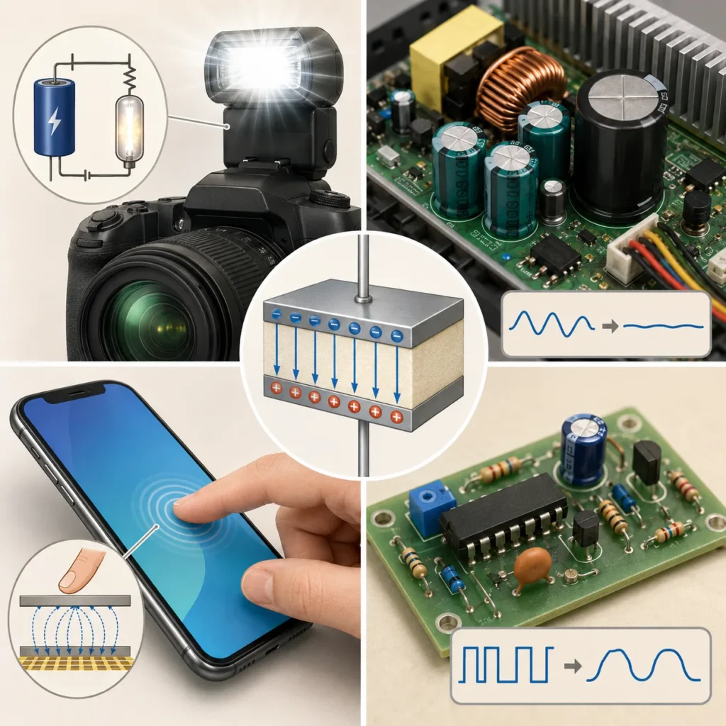
This illustration shows several real-world uses of capacitors, including camera flashes, circuit boards, power supply electronics, signal control, and touchscreen sensing. These examples help students see that capacitance is not only a classroom idea. Capacitors are used whenever devices need to store electrical energy, smooth voltage changes, shape signals, or detect changes in electric fields.
Bridge to University Thinking
Quick Interactive Check
Suggested answer: Its capacitance has increased. Capacitance measures charge stored per volt.
Suggested answer: The capacitance increases. Larger plate area allows more charge separation for the same voltage.
Suggested answer: The capacitance decreases. Larger plate separation makes it harder for the system to store charge for the same voltage.
Suggested answer: No. A dielectric increases capacitance through polarisation, not ordinary conduction.
Suggested answer: The energy is stored in the electric field between the plates.
Review Questions and Answers
- What is capacitance?Answer: Capacitance is the physical ability of a system to store separated electric charge per unit voltage drop. It is mathematically defined by the ratio C = Q / V.
- What is the SI unit of capacitance?Answer: The SI unit of capacitance is the farad, represented by the uppercase symbol F. One farad equals one coulomb per single volt (1 C/V).
- What is a capacitor?Answer: A capacitor is an engineered electrical system consisting of conductive boundaries separated by an insulating dielectric space, used to maintain charge arrays and store volumetric field energy.
- How does increasing plate area affect capacitance?Answer: Increasing the plate surface area provides more physical space for charge distribution, reducing mutual repulsions and directly increasing net capacitance.
- How does increasing plate separation affect capacitance?Answer: Increasing plate separation weakens the binding electrostatic attraction vectors across the gap, lowering the system’s storage efficiency and decreasing capacitance.
- What is a dielectric?Answer: A dielectric is an insulating material with high electrical permittivity. It polarizes at the molecular level in an electric field, creating an opposing field that increases overall capacitance.
- What does the dielectric constant (κ) represent?Answer: The dimensionless dielectric constant κ represents the material’s relative permittivity, scaling the base storage capacity compared to a vacuum enclosure.
- Where is energy stored in a capacitor?Answer: Potential energy is stored volumetrically inside the localized electrostatic field established between the boundary conductors.
Thought-Provoking Questions and Answers
- Why is it more accurate to say that a capacitor stores energy in an electric field rather than simply saying it stores charge?Suggested answer: Charge separation acts as the physical source that establishes the electric field, but the system’s actual potential energy is stored within the continuous spatial field lines. Modeling energy storage as a volumetric property of the field provides a mathematically accurate framework that scales directly into advanced electrodynamics.
- Why does a dielectric increase capacitance even though it is an insulator?Suggested answer: A dielectric does not rely on free charge migration to modify system mechanics. When exposed to an external field, its bounded electron clouds polarize, shifting slightly to create an internal induced field that opposes the primary field. This reduces the potential difference across the plates, allowing additional charge to accumulate at the same operating voltage.
- Why might the geometry of a capacitor matter as much as the material used?Suggested answer: Capacitance is defined by a balance of structural design and material physics. Plate area and separation establish the base geometric parameters for cross-gap force vectors, while the dielectric permittivity scales the total field density those configurations can sustain.
- How does capacitance connect electrostatics to circuits?Suggested answer: In electrostatics, capacitance quantifies spatial charge separation and field energy limits. In active circuitry, these properties let capacitors resist sudden voltage drops, smooth alternating ripples, filter noise frequencies, and discharge energy rapidly.
- Why can a simple capacitor be considered a bridge between physics and technology?Suggested answer: A capacitor combines abstract physics principles—including continuous field integrals, material polarization vectors, and scalar energy distributions—into a core component used across consumer electronics, power grids, and medical diagnostics.
Numerical Problems and Solutions
-
A capacitor stores 4.0 × 10⁻⁶ C of charge when the voltage across it is 8.0 V. Find the capacitance.Solution: Apply the base capacitance definition:$$C = \frac{Q}{V}$$ $$C = \frac{4.0 \times 10^{-6}\text{ C}}{8.0\text{ V}}$$ $$C = 5.0 \times 10^{-7}\text{ F} = 0.50\text{ }\mu\text{F}$$Interpretation: The system stores exactly half a microcoulomb of separated charge for each individual volt applied across its plates.
-
A 2.0 μF capacitor is connected to a 9.0 V battery. How much charge is stored on one plate?Solution: Rearrange the primary ratio equation to isolate charge magnitude:$$Q = CV$$ $$Q = (2.0 \times 10^{-6}\text{ F})(9.0\text{ V})$$ $$Q = 1.8 \times 10^{-5}\text{ C}$$Interpretation: The conductor surface holds a charge magnitude of 1.8 × 10⁻⁵ C, establishing equal and opposite charge boundaries (+Q and -Q).
-
A parallel-plate capacitor has plate area 0.020 m² and separation 1.0 × 10⁻³ m. Estimate its capacitance in air using ε0 = 8.85 × 10⁻¹² F/m.Solution: Deploy the ideal geometric calculation model:$$C = \frac{\varepsilon_0 A}{d}$$ $$C = (8.85 \times 10^{-12}\text{ F/m}) \frac{0.020\text{ m}^2}{1.0 \times 10^{-3}\text{ m}}$$ $$C = 1.77 \times 10^{-10}\text{ F} \approx 180\text{ pF}$$Interpretation: The system’s baseline geometric capacity yields 180 pF of charge storage efficiency in an air-filled gap.
-
A dielectric with κ = 4.0 is inserted fully between the plates of a capacitor whose original capacitance is 3.0 nF. Find the new capacitance.Solution: Scale the base vacuum capacitance by the material permittivity multiplier:$$C = \kappa C_0$$ $$C = (4.0)(3.0\text{ nF})$$ $$C = 12\text{ nF}$$Interpretation: Microscopic polarization within the dielectric material increases the system’s charge storage capability by a factor of four.
-
A 5.0 μF capacitor is charged to 20 V. Find the energy stored.Solution: Compute potential energy storage using the quadratic field equation:$$U = \frac{1}{2} C V^2$$ $$U = 0.5 \times (5.0 \times 10^{-6}\text{ F})(20\text{ V})^2$$ $$U = 0.5 \times (5.0 \times 10^{-6}) \times 400 = 1.0 \times 10^{-3}\text{ J} = 1.0\text{ mJ}$$Interpretation: The system stores exactly 1.0 mJ of potential energy inside the electrostatic field lines spanning the gap.
Summary
Glossary
- Capacitance
- The ability of a system to store electric charge per unit voltage, defined by the ratio C = Q / V.
- Capacitor
- A physical device or system of conductors separated by an insulating region, designed to maintain charge separation and store electric field energy.
- Farad
- The SI unit of capacitance; defined as storing one coulomb of charge per individual volt of potential difference.
- Parallel-Plate Capacitor
- A capacitor configuration consisting of two parallel conducting boundaries separated by a uniform microscopic gap distance.
- Dielectric
- An insulating material placed within an electric field that undergoes atomic polarization to increase system capacitance.
- Dielectric Constant (κ)
- A dimensionless ratio tracking a material’s relative permittivity and capacity to scale vacuum storage limits.
- Polarisation
- The localized microscopic alignment of atomic charges within an insulator in response to an external electric field vector.
- Electric Field Energy
- The potential energy stored volumetrically within the electrostatic field lines spanning the gap between conductors.
- Plate Separation
- The physical distance gap separating the conductive boundaries of a capacitor.
- Permittivity
- A material parameter quantifying an insulator’s electric response and structural influence on local field configurations.
Frequently Asked Questions
What does capacitance measure?
Capacitance measures a system’s electrical storage efficiency, tracking the explicit volume of separated charge held per single volt of potential drop across system boundaries.
Does a capacitor store charge or energy?
A capacitor holds equal and opposite charge arrays on its conductive boundaries, but the system’s actual potential energy is stored volumetrically within the electric field lines spanning the gap volume.
Why does a dielectric increase capacitance?
A dielectric undergoes microscopic molecular polarization in an electric field. This alignment creates an internal reverse field that partially screens the primary field, lowering voltage drops to permit additional charge storage.
Is a dielectric the same as a conductor?
No. A dielectric is a pure insulator. It blocks free electron migration across system boundaries while permitting localized atomic polarization to modify field behaviors safely.
Why does increasing plate area increase capacitance?
Expanding boundary surface area provides a wider spatial zone for charge arrays to distribute, minimizing mutual repulsions and allowing more charge to accumulate at a given voltage level.
Why does increasing plate separation reduce capacitance?
Increasing the spatial separation gap weakens the attractive mutual electrostatic forces across the boundaries, lowering the system’s ability to pull and maintain high charge densities efficiently.
Authoritative External References
- OpenStax University Physics Volume 2: Capacitors and Capacitance — A comprehensive, peer-reviewed academic resource detailing structural geometry derivations and ideal field equations.
- The Feynman Lectures on Physics, Vol. II, Chapter 11: Dielectrics — Caltech’s definitive source on advanced electrostatic physics, providing deep mathematical insights into molecular polarization vectors and internal displacement fields.
- NIST Physical Reference Data — The National Institute of Standards and Technology portal, confirming exact fundamental constant values for the permittivity of free space (ε0) and material dielectric matrices.